EP0954403B1 - Molekulare verbindung von fahrzeugrahmenbauteilen mittels magnetimpulsschweissen - Google Patents
Molekulare verbindung von fahrzeugrahmenbauteilen mittels magnetimpulsschweissen Download PDFInfo
- Publication number
- EP0954403B1 EP0954403B1 EP96919454A EP96919454A EP0954403B1 EP 0954403 B1 EP0954403 B1 EP 0954403B1 EP 96919454 A EP96919454 A EP 96919454A EP 96919454 A EP96919454 A EP 96919454A EP 0954403 B1 EP0954403 B1 EP 0954403B1
- Authority
- EP
- European Patent Office
- Prior art keywords
- vehicle frame
- side rail
- providing
- metallic
- components
- Prior art date
- Legal status (The legal status is an assumption and is not a legal conclusion. Google has not performed a legal analysis and makes no representation as to the accuracy of the status listed.)
- Expired - Lifetime
Links
- 238000000034 method Methods 0.000 title claims description 35
- 238000003466 welding Methods 0.000 title description 15
- 239000007769 metal material Substances 0.000 claims description 17
- 238000005304 joining Methods 0.000 claims description 9
- 230000005672 electromagnetic field Effects 0.000 claims description 8
- 238000004519 manufacturing process Methods 0.000 claims description 4
- 239000003990 capacitor Substances 0.000 description 14
- 238000005452 bending Methods 0.000 description 6
- FYYHWMGAXLPEAU-UHFFFAOYSA-N Magnesium Chemical compound [Mg] FYYHWMGAXLPEAU-UHFFFAOYSA-N 0.000 description 4
- 229910052782 aluminium Inorganic materials 0.000 description 4
- XAGFODPZIPBFFR-UHFFFAOYSA-N aluminium Chemical compound [Al] XAGFODPZIPBFFR-UHFFFAOYSA-N 0.000 description 4
- 229910052749 magnesium Inorganic materials 0.000 description 4
- 239000011777 magnesium Substances 0.000 description 4
- 239000000463 material Substances 0.000 description 4
- 229910052751 metal Inorganic materials 0.000 description 4
- 239000002184 metal Substances 0.000 description 4
- 229910000831 Steel Inorganic materials 0.000 description 3
- 239000004020 conductor Substances 0.000 description 3
- 239000012530 fluid Substances 0.000 description 3
- 239000010959 steel Substances 0.000 description 3
- 230000015572 biosynthetic process Effects 0.000 description 2
- 238000004581 coalescence Methods 0.000 description 1
- 238000005260 corrosion Methods 0.000 description 1
- 230000007797 corrosion Effects 0.000 description 1
- 239000000945 filler Substances 0.000 description 1
- 239000003562 lightweight material Substances 0.000 description 1
- 150000002739 metals Chemical class 0.000 description 1
- 238000004804 winding Methods 0.000 description 1
Images


Classifications
-
- B—PERFORMING OPERATIONS; TRANSPORTING
- B23—MACHINE TOOLS; METAL-WORKING NOT OTHERWISE PROVIDED FOR
- B23K—SOLDERING OR UNSOLDERING; WELDING; CLADDING OR PLATING BY SOLDERING OR WELDING; CUTTING BY APPLYING HEAT LOCALLY, e.g. FLAME CUTTING; WORKING BY LASER BEAM
- B23K20/00—Non-electric welding by applying impact or other pressure, with or without the application of heat, e.g. cladding or plating
- B23K20/06—Non-electric welding by applying impact or other pressure, with or without the application of heat, e.g. cladding or plating by means of high energy impulses, e.g. magnetic energy
-
- B—PERFORMING OPERATIONS; TRANSPORTING
- B21—MECHANICAL METAL-WORKING WITHOUT ESSENTIALLY REMOVING MATERIAL; PUNCHING METAL
- B21D—WORKING OR PROCESSING OF SHEET METAL OR METAL TUBES, RODS OR PROFILES WITHOUT ESSENTIALLY REMOVING MATERIAL; PUNCHING METAL
- B21D53/00—Making other particular articles
- B21D53/88—Making other particular articles other parts for vehicles, e.g. cowlings, mudguards
-
- B—PERFORMING OPERATIONS; TRANSPORTING
- B23—MACHINE TOOLS; METAL-WORKING NOT OTHERWISE PROVIDED FOR
- B23K—SOLDERING OR UNSOLDERING; WELDING; CLADDING OR PLATING BY SOLDERING OR WELDING; CUTTING BY APPLYING HEAT LOCALLY, e.g. FLAME CUTTING; WORKING BY LASER BEAM
- B23K9/00—Arc welding or cutting
- B23K9/08—Arrangements or circuits for magnetic control of the arc
-
- B—PERFORMING OPERATIONS; TRANSPORTING
- B23—MACHINE TOOLS; METAL-WORKING NOT OTHERWISE PROVIDED FOR
- B23K—SOLDERING OR UNSOLDERING; WELDING; CLADDING OR PLATING BY SOLDERING OR WELDING; CUTTING BY APPLYING HEAT LOCALLY, e.g. FLAME CUTTING; WORKING BY LASER BEAM
- B23K2101/00—Articles made by soldering, welding or cutting
- B23K2101/24—Frameworks
-
- B—PERFORMING OPERATIONS; TRANSPORTING
- B23—MACHINE TOOLS; METAL-WORKING NOT OTHERWISE PROVIDED FOR
- B23K—SOLDERING OR UNSOLDERING; WELDING; CLADDING OR PLATING BY SOLDERING OR WELDING; CUTTING BY APPLYING HEAT LOCALLY, e.g. FLAME CUTTING; WORKING BY LASER BEAM
- B23K2101/00—Articles made by soldering, welding or cutting
- B23K2101/26—Railway- or like rails
Definitions
- This invention relates in general to the manufacture and assembly of vehicle frame components and in particular to a method and apparatus for permanently joining two or more metallic vehicle frame components using magnetic impulse welding techniques.
- Many vehicle frame structures are known in the art. Most of these known vehicle frame structures are formed from a number of individual metallic components which are permanently joined together.
- a typical vehicle frame is composed of a pair of longitudinally extending side rails which are joined together by a plurality of transversely extending cross members.
- the side rails can be formed from a single piece of metal.
- each of the side rails is usually formed from two or more side rail sections which are permanently joined together. In either event, the side rails and cross members, once joined together, form a frame for supporting the remaining portions of the vehicle thereon.
- brackets, hangers, cradles, and the like are often joined to the side rails and cross members at desired locations. It is common practice to also form these supporting hardware components from metallic materials, and further to permanently join them to the side rails and cross members at desired locations.
- This invention relates to a method for manufacturing a vehicle frame assembly according to claim 1.
- the vehicle frame may include a pair of open channel side rails which are joined together by a plurality of transversely extending cross members.
- a plurality of brackets are joined to the side rails to facilitate the attachment of other portions of the vehicle to the vehicle frame.
- An overlap joint is formed by the joinder of two individual side rail sections to form a portion of a side rail.
- the first side rail section is initially formed slightly smaller in size than the second side rail section so that it may be disposed telescopically therein with clearance.
- An electromagnetic coil is provided for generating a magnetic field which causes the side rail sections to move toward one another. Portions of the electromagnetic coil are disposed on either side of the side rail sections.
- a first end of the electromagnetic coil is connected through a switch to a first side of a capacitor, while a second end of the electromagnetic coil is connected directly to a second side of the capacitor.
- a source of electrical energy is provided for selectively charging the capacitor to store a quantity of electrical energy therein.
- By closing the switch electrical energy is passed from the capacitor through the electromagnetic coil.
- an intense electromagnetic field is generated about the first and second side rail sections.
- the presence of this electromagnetic field induces electrical currents in the first and second side rail sections.
- These electrical currents create opposing magnetic fields which draw the first and second side rail sections into contact with one another.
- large pressures exerted on the first and second side rail sections can move them toward one another at great velocities.
- the high velocity impact and the large pressures cause the two side rail sections to weld or molecularly bond.
- a bracket can be joined to a side rail section in a similar manner.
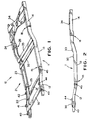
- the frame 10 includes a first side rail, indicated generally at 11, which extends longitudinally throughout the length of the vehicle in which it is to be used.
- the first side rail 11 is formed from three individual side rail sections 12, 13, and 14.
- the first and second side rail sections 12 and 13 are joined at an overlap joint, indicated generally at 15.
- the second and third side rail sections 13 and 14 are joined at an overlap joint, indicated generally at 16.
- the structures of the individual side rail sections 12, 13, and 14 and of the overlap joints 15 and 16 of the first side rail 11 will be described in further detail below.
- the frame 10 further includes a second side rail, indicated generally at 21, which also extends longitudinally throughout the length of the vehicle in which it is to be used.
- the second side rail 21 is formed in a similar manner as the first side rail 11, including first, second, and third individual side rail sections 22, 23, and 24 which are joined at overlap joints 25 and 26.
- the side rails 11 and 21 are joined together by a plurality of transversely extending cross members 30, 31, 32, 33, and 34. These cross members 30 through 34 vary in size and shape and are intended to represent any type of cross member, cradle, or other structure which extends between the two side rails 11 and 21.
- the basic structures of cross member of this type are well known in the art.
- a plurality of brackets 40, 41, 42, 43, 44, and 45 are joined to the side rails 11 and 21.
- These brackets 40 through 45 also vary in size and shape and are intended to represent any type of bracket, hanger, or other structure which is joined to the side rails 11 and 21.
- the basic structures of these brackets are also well known in the art.
- the various components of the vehicle frame 10 discussed above are all formed from metallic materials.
- steel has been found to be an acceptable material to form these various components.
- this invention contemplates that other metallic materials may be used, such as aluminum, magnesium, and the like may be used.
- all of the various components of the vehicle frame 10 need not be formed from the same metallic material. Rather, some of such components may be formed from a first metallic material, while others may be formed from a second metallic material.
- the vehicle frame 10 is formed by joining the various side rails 11 and 21, cross members 30 through 34, and brackets 40 through 45 together. Some of these components may be joined together by the use of mechanical fasteners, such as bolts, if desired. However, this invention relates to a method and apparatus for permanently joining these components together using a magnetic impulse welding techniques, which will be described below. Magnetic impulse welding techniques have been found to be preferable to conventional welding techniques in the formation of vehicle frames, as discussed above.
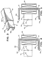
- FIG. 3 there is illustrated an enlarged perspective view of the overlap joint 15 between the ends of the individual side rail sections 12 and 13 illustrated in Figs. 1 and 2.
- the rearward end of the first side rail section 12 includes a vertically extending web portion having an upper horizontal flange portion 12a and a lower horizontal flange portion 12b extending therefrom.
- the forward end of the second side rail section 13 includes a vertically extending web portion having an upper horizontal flange portion 13a and a lower horizontal flange portion 13b extending therefrom.
- the ends of the first and second side rail sections 12 and 13 are shown as having generally open channel or C-shaped cross sectional shapes, it will be appreciated that they may be formed having other cross sectional shapes.
- first and second side rail sections 12 and 13 need not be uniform throughout their entire lengths, nor does the cross sectional shape of the first side rail section 12 have to be the same as the cross sectional shape of the second side rail section 13.
- the first side rail section 12 is initially formed slightly smaller in size than the second side rail section 13, prior to being joined together.
- the first side rail section 12 may initially be disposed telescopically within the second side rail section 13 with clearance, as shown in Fig. 4.
- the vertically extending web portions of the side rail sections 12 and 13 are disposed generally parallel and adjacent to one another, as are the upper horizontal flange portions 12a and 13a and the lower horizontal flange portions 12b and 13b.
- the clearance between the respective portions of the side rail sections 12 and 13 may be adjusted as desired, it has been found acceptable to provide a clearance in the range of aprox 1,27 mm to 2,54 mm (from 0.050 inch to 0.100 inch).
- An electromagnetic coil 50 is provided for generating a magnetic field which, as will be explained further below, causes the side rail sections 12 and 13 to move toward one another. Portions of the electromagnetic coil 50 are disposed on either side of the side rail sections 12 and 13.
- the electromagnetic coil 50 is embodied as a plurality of windings of an electrical conductor. A first end of the electrical conductor is connected through a first switch 51 to a first side of a capacitor 52, while a second end of the electrical conductor is connected directly to a second side of the capacitor 52.
- the capacitor 52 is representative of a number of high voltage capacitors which are connected together in parallel.
- a source of electrical energy 53 is provided for selectively charging the capacitor 52 to store a quantity of electrical energy therein. A first side of the source of electrical energy 53 is connected through a second switch 54 to the first side of the capacitor 52, while a second side of the source of electrical energy 53 is connected directly to the second side of the capacitor 52.
- the first switch 51 is initially opened and the second switch 54 is initially closed, as shown in Fig. 4.
- electrical energy is transferred from the source of electrical energy 53 into the capacitor 52.
- the second switch 54 is opened and the first switch 51 is closed, as shown in Fig. 5.
- energy in the form of electrical current is discharged from the capacitor 52 through the electromagnetic coil 50.
- an intense electromagnetic field is generated about the first and second side rail sections.
- the presence of this electromagnetic field induces electrical currents in the first and second side rail sections 12 and 13.
- These electrical currents create opposing magnetic fields which draw the first and second side rail sections 12 and 13 into contact with one another. When this occurs, a large pressure exerted on the first and second side rail sections 12 and 13 move them toward one another at a high velocity.
- the sizes and shapes of the side rail sections 12 and 13, the size and shape of the electromagnetic coil 50, and the strength of the electromagnetic field are all factors which will determine where the deformation of the first and second side rail sections 12 and 13 will occur, as well as which portions thereof will be joined together.
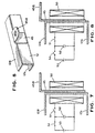
- the first side rail section 12 includes the vertically extending web portion having the upper horizontal flange portion 12a and the lower horizontal flange portion 12b extending therefrom.
- the bracket 45 is formed having a vertically extending web portion having an upper horizontal flange portion 45a extending therefrom.
- the vertically extending web portions of the first side rail section 12 and the bracket 45 are disposed in spaced apart relationship, generally parallel and adjacent to one another as shown in Fig. 7.
- Portions of the electromagnetic coil 50 are disposed on either side of the side rail section 12 and the bracket 45. The operation of the electromagnetic coil 50 is the same as described above, and functions to weld or molecularly bond the side rail section 12 with the bracket 45, as shown in Fig. 8.
- Fig. 9 illustrates an alternative structure for securing the side rail 12 and the bracket 45 together.
- the coil 50 is disposed concentrically about an elongated cylindrical mandrel 46.
- the mandrel 46 is formed from a material which, when a magnetic field is generated by energization of the electromagnetic coil 50, is urged for movement in the direction indicated by the arrow.
- One end of the mandrel 46 is located adjacent to the vertically extending web portion of the bracket 45.
- the bracket 45 may be secured to the end of the mandrel 45 or may simply be disposed adjacent thereto.
- the bracket 45 is welded or molecularly bonded to the side rail 12 similarly as described above.
- the side rails 11 and 12 described above are all shown as being formed from open channel stock, i.e., stock which has a non-closed cross sectional shape.
- the specifically illustrated side rails 11 and 12 are formed having a generally open C-shaped cross section. It will be appreciated that this invention may be practiced using open channel stock having other cross sectional shapes.
- the side rails 11 and 12 may be formed having a generally closed C-shaped cross section (wherein short flanges are provided at the ends of the illustrated side rails 11 and 12 which extend inwardly toward one another), a generally hat-shaped cross section (wherein short flanges are provided at the ends of the illustrated side rails 11 and 12 which extend outwardly apart from one another), or other open channel configurations.
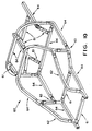
- the illustrated vehicle frame assembly 60 is an automobile space frame, i.e., a frame for an automobile which defines an enclosed space for occupants.
- this invention may be utilized in a flat bed frame or any other frame structure for any type of vehicle.
- the illustrated vehicle frame assembly 60 is composed of four different types of structural components which are secured together.
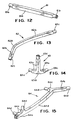
- the first type of structural component is referred to as a straight member, such as shown at 61.
- Straight members 61 are characterized as being linear and elongated in shape.
- the straight members 61 are hollow and can be formed having any desired cross sectional shape.
- a straight member 61 may be formed having a central portion 61 a which is square or rectangular in cross sectional shape and a pair of end portions 61b which are circular in cross sectional shape.
- the square or rectangular cross sectional shape of the central portion 61a of the straight member 61 is desirable because it provides stiffness to the straight member 61 and facilitates the attachment of other components thereto, such as brackets and the like.
- the circular cross sectional shape of the end portions 61b of the straight member 61 is desirable because it facilitates the attachment of other structural components of the vehicle frame assembly 60.
- the second type of structural component in the vehicle frame assembly 60 is referred to as a curved member, such as shown at 62.
- Curved members 62 are similar to straight members 61 in that they are hollow and elongated. However, curved members 62 are not linear in shape like the straight members 61, but rather extend non-linearly.
- a curved member 62 may be formed having a single bend portion 62a which is located between two linear portions 62b. Alternatively, the curved member 62 may be formed having a plurality of bend portions 62a separating adjacent linear portions 62b, or it may be curved along its entire length.
- the linear portions 62b near the center of the curved member 62 are square or rectangular in cross sectional shape.
- Two end portions 62c are provided on the curved member 62 which are circular in cross sectional shape, also for the same reasons as stated above.
- the third type of structural component in the vehicle frame assembly 60 is referred to as a joint node, such as shown at 63.
- Joint nodes 63 are characterized as relatively small components which are provided to join adjacent components of the vehicle frame assembly 60 at a joint.
- a joint node 63 may be formed having a relatively small body portion 63a with a plurality (three in the illustrated embodiment) relatively short joint portions 63b extending outwardly therefrom.
- the joint portions 63b are typically linear because of their relatively short length, although such is not required.
- the body portion 63a and the joint portions 63b are hollow and can be formed having any desired cross sectional shape.
- the body portion 63a and adjacent areas of the joint portions 63b are preferably square or rectangular in cross sectional shape.
- Two end portions 63c are provided on the joint member 63 which are circular in cross sectional shape, also for the same reasons as stated above.
- the fourth type of structural component in the vehicle frame assembly 60 is referred to as a member node, such as shown at 64.
- Member nodes 64 are characterized as elongated components which are also provided to join adjacent components of the vehicle frame assembly 60 at a joint.
- a member node 64 may be formed having an elongated central portion 64a, a pair of end portions 64b, and one or more (three in the illustrated embodiment) relatively short joint portions 64c extending outwardly therefrom.
- the joint portions 64c are typically linear because of their relatively short length, although such is not required.
- the central portion 64a, the end portions 64b, and the joint portions 64c are hollow and can be formed having any desired cross sectional shape.
- the central portion 64a and adjacent areas of the joint portions 64c are preferably square or rectangular in cross sectional shape.
- End portions 62d are provided on the curved member 62 which are circular in cross sectional shape, also for the same reasons as stated above.
- Each of the four types of structural components 61, 62, 63, and 64 used to form the vehicle frame assembly 60 is preferably formed by hydroforming techniques.
- Hydroforming is a metal deformation process which, generally speaking, utilizes high pressure fluid introduced within a closed workpiece to expand portions of the workpiece outwardly into conformance with an enclosing die.
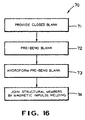
- Fig. 16 is a flowchart 70 which illustrates the steps in the hydroforming process of this invention for forming any one or all of the four types of structural components 61, 62, 63, and 64 used to form the vehicle frame assembly 60.
- the first step 71 in the hydroforming process is to provide a closed blank.
- the closed blank is a tubular blank having a uniform circular cross sectional shape and formed from a metallic material.
- relatively lightweight strong metallic materials such as aluminum, magnesium, and the like, be used.
- steel and other heavier metallic materials may be used as well.
- pre-bend the tubular blank into a preform shape as shown at 72.
- Such pre-bending is necessary when the final desired shape of the structural component is dramatically different from the initial shape of the tubular blank.
- pre-bending may not be required when forming a straight member 61 because of its generally linear shape, but may be required when forming a curved member 62.
- Several pre-bending operations may be performed on a single blank, depending upon the final desired shape for the structural component. Following this pre-bending. the blank follows the general shape of the structural component to be formed, but still has a generally uniform circular cross sectional shape throughout its entire length.
- the pre-bending step may be performed on a conventional tube bending apparatus or other similar mechanism.
- the pre-bent blank is disposed within a hydroforming die, and highly pressurized fluid is introduced therein, as shown at 73.
- the highly pressurized fluid within the pre-bent blank causes portions thereof to expand outwardly into conformance with the enclosed hydroforming die.
- the portions of the structural members 61, 62, 63, and 64 having the square or rectangular cross sectional shapes discussed above can be formed.
- various openings (not shown) or other structures may be formed on the structural components as desired, such as for facilitating the connection of other components (brackets, etc.) to the vehicle frame assembly 60.
- the hydroforming step can be performed on any conventional hydroforming apparatus.
- the final step in the process of forming the vehicle frame assembly is to join the formed structural members together, as shown at 74 in the flowchart 70.
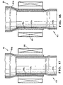
- Figs. 17 and 18 the formation of a joint between one of the straight members 61 and one of the joint nodes 63 is illustrated.
- the end portion 61b of the straight member 61 is initially formed slightly larger in size than the end portion 63c of the joint portion 63b of the joint node 63, prior to being joined together.
- the end portion 63c of the joint node 63 may initially be disposed telescopically within the end portion 61b of the straight member 61 with an annular clearance, as shown in Fig. 17.
- the outer cylindrical surface of the end portion 63c of the joint node 63 is disposed generally concentric with the inner cylindrical surface of the end portion 61b of the straight member 61.
- the clearance between these cylindrical surfaces may be adjusted as desired, it has been found acceptable to provide a clearance in the range of from aprox 1,27 mm to 2,54 mm (0.050 inch to 0.100 inch).
- An electromagnetic coil 80 is provided for generating a magnetic field which, as will be explained further below, causes the end portion 63c of the joint node 63 and the end portion 61b of the straight member 61 to move toward one another.
- the electromagnetic coil 80 is disposed concentrically about the end portion 61b of the straight member 61.
- the electromagnetic coil 80 is similar in structure and operation to the electromagnetic coil 50 described above, and the same control circuit may be used to operate same.
- the electromagnetic field generated by the coil 80 causes the end portion 61b of the straight member 61 to move toward the end portion 63c of the joint node 63 at a high velocity.
- the end portion 61b of the straight member 61 and the end portion 63c of the joint node 63 are welded or molecularly bonded as described above.
- the various components of the vehicle frame 60 need not be formed from the same metallic material. Rather, some of such components may be formed from a first metallic material, while others may be formed from a second metallic material.
- the various structural components which are located in the upper portion of the vehicle frame assembly 60 i.e., those structural components which extend upwardly from the bed portion of the vehicle frame assembly 60 to form the sides and roof of the passenger compartment
- the various structural components which are located in the lower portion of the vehicle frame assembly 60 i.e., those structural components which form the bed portion of the vehicle frame assembly 60
- a second relatively heavier material such as aluminum.
- steel may be used in portions of the vehicle frame assembly 60 in conjunction with either or both of the magnesium and aluminum materials.
- the above-described process for molecular bonding of vehicle frame components using magnetic impulse welding techniques is advantageous because the adjacent dissimilar metals have been found not to cause corrosion when joined in this manner.
Landscapes
- Engineering & Computer Science (AREA)
- Mechanical Engineering (AREA)
- Physics & Mathematics (AREA)
- Plasma & Fusion (AREA)
- Body Structure For Vehicles (AREA)
- Pressure Welding/Diffusion-Bonding (AREA)
Claims (6)
- Verfahren zum Herstellen einer Fahrzeugrahmenanordnung (10), welches die folgenden Schritte aufweist:a) Vorsehen einer ersten metallischen Fahrzeugrahmenkomponente aus einer Gruppe, welche einen Längsträger (12, 13, 14, 22, 23, 24), einen Querträger (30, 31, 32, 33, 34) und ein Tragteil (45) umfaßt;b) Vorsehen einer zweiten metallischen Fahrzeugrahmenkomponente aus einer Gruppe, welche einen Längsträger (12, 13, 14, 22, 23, 24), einen Querträger (30, 31, 32, 33, 34) und ein Tragteil (45) umfaßt;c) Anordnen von Abschnitten der ersten und der zweiten Fahrzeugrahmenkomponenten in einer überlappenden Zuordnung;d) Vorsehen einer elektromagnetischen Spule (50) um die überlappenden Abschnitte der ersten und der zweiten Fahrzeugrahmenkomponenten;e) Verbinden der elektromagnetischen Spule (50) mit einer elektrischen Energiequelle derart, daß ein elektromagnetisches Feld erzeugt wird, wodurch bewirkt wird, daß die ersten und die zweiten Fahrzeugrahmenkomponenten sich in Kontakt miteinander mit einer hohen Geschwindigkeit derart bewegen, daß sie miteinander verbunden werden;f) Vorsehen einer Mehrzahl von weiteren Fahrzeugrahmenkomponenten; undg) Verbinden aller Fahrzeugrahmenkomponenten zur Bildung einer Fahrzeugrahmenanordnung (10).
- Verfahren nach Anspruch 1, bei dem der Schritt (a) dadurch ausgeführt wird, daß ein erster, metallischer Längsträger (12) mit einem Hohlprofilquerschnitt vorgesehen wird, und daß der Schritt (b) dadurch ausgeführt wird, daß ein zweiter, metallischer Längsträger (13) mit einem Hohlprofilquerschnitt vorgesehen wird.
- Verfahren nach Anspruch 1, bei dem der Schritt (a) dadurch ausgeführt wird, daß ein erster metallischer Längsträger (12) mit einem im allgemeinen C-förmigen Querschnitt vorgesehen wird, und daß der Schritt (b) dadurch ausgeführt wird, daß ein zweiter, metallischer Längsträger (13) mit einem im wesentlichen C-förmigen Querschnitt vorgesehen wird.
- Verfahren nach Anspruch 1, bei dem die erste Fahrzeugrahmenkomponente aus einem ersten metallischen Material ausgebildet ist, und die zweite Fahrzeugrahmenkomponente aus einem zweiten metallischen Material ausgebildet ist, welches sich von dem ersten metallischen Material unterscheidet.
- Verfahren nach Anspruch 1, bei dem die elektromagnetische Spule konzentrisch um die überlappenden Abschnitte der ersten und der zweiten Fahrzeugrahmenkomponenten angeordnet ist.
- Verfahren nach Anspruch 1, bei dem der Schritt (c) den Schritt umfaßt, gemäß welchem ein Dorn (46) vorgesehen wird, welcher derart beschaffen und ausgelegt ist, daß er mit der ersten Fahrzeugrahmenkomponente zusammenarbeitet, und bei dem der Schritt (e) einen Schritt umfaßt, gemäß dem das elektromagnetische Feld derart erzeugt wird, daß eine Bewegung des Dorns zur Bewegung der ersten Fahrzeugrahmenkomponente in Kontakt mit der zweiten Fahrzeugrahmenkomponente mit einer hohen Geschwindigkeit durchgeführt wird, so daß die ersten und die zweiten Fahrzeugrahmenkomponenten ständig miteinander verbunden werden.
Applications Claiming Priority (3)
| Application Number | Priority Date | Filing Date | Title |
|---|---|---|---|
| US491284 | 1983-05-03 | ||
| US49128495A | 1995-06-16 | 1995-06-16 | |
| PCT/US1996/010428 WO1997000151A2 (en) | 1995-06-16 | 1996-06-14 | Molecular bonding of vehicle frame components using magnetic impulse welding techniques |
Publications (3)
| Publication Number | Publication Date |
|---|---|
| EP0954403A2 EP0954403A2 (de) | 1999-11-10 |
| EP0954403A4 EP0954403A4 (de) | 2000-12-20 |
| EP0954403B1 true EP0954403B1 (de) | 2005-02-09 |
Family
ID=23951550
Family Applications (1)
| Application Number | Title | Priority Date | Filing Date |
|---|---|---|---|
| EP96919454A Expired - Lifetime EP0954403B1 (de) | 1995-06-16 | 1996-06-14 | Molekulare verbindung von fahrzeugrahmenbauteilen mittels magnetimpulsschweissen |
Country Status (5)
| Country | Link |
|---|---|
| US (1) | US6104012A (de) |
| EP (1) | EP0954403B1 (de) |
| BR (1) | BR9609002A (de) |
| DE (1) | DE69634343T2 (de) |
| WO (1) | WO1997000151A2 (de) |
Families Citing this family (27)
| Publication number | Priority date | Publication date | Assignee | Title |
|---|---|---|---|---|
| US6812439B1 (en) * | 1995-06-16 | 2004-11-02 | Dana Corporation | Molecular bonding of vehicle frame components using magnetic impulse welding techniques |
| US6138358A (en) * | 1999-02-18 | 2000-10-31 | Dana Corporation | Method of manufacturing a vehicle body and frame assembly |
| JP2003505255A (ja) * | 1999-08-02 | 2003-02-12 | デーナ、コーポレイション | 磁気インパルス溶接技法を使用する車両クレーム構成部分の分子結合 |
| US6255631B1 (en) * | 1999-11-29 | 2001-07-03 | Dana Corporation | Apparatus and method for joining vehicle frame components |
| MXPA02010588A (es) | 2000-04-26 | 2003-05-14 | Cosma Int Inc | Hidroconformacion de una estructura tubular de diametro variable a partir de una pieza preformada tubular, usando soldadura de impulsos electromagneticos. |
| DE10024819A1 (de) * | 2000-05-19 | 2001-11-22 | Bayerische Motoren Werke Ag | Verfahren zur Herstellung einer Bremsscheibe |
| DE10045230A1 (de) * | 2000-09-13 | 2002-03-28 | Bayerische Motoren Werke Ag | Herstellverfahren für einen Fahrzeughilfsrahmen |
| US6438839B1 (en) * | 2001-01-26 | 2002-08-27 | Delphi Technologies, Inc. | Method of manufacturing a catalytic converter by induction welding |
| US6654995B1 (en) * | 2000-10-16 | 2003-12-02 | General Motors Corporation | Method for joining tubular members |
| US7632671B2 (en) * | 2001-11-29 | 2009-12-15 | Sun-Wing Tong | Molecular detection and assay by electrobiochip micro-array |
| US6875964B2 (en) | 2002-05-07 | 2005-04-05 | Ford Motor Company | Apparatus for electromagnetic forming, joining and welding |
| US20050035586A1 (en) * | 2003-08-12 | 2005-02-17 | Martin Samuel V. | Magnetically pulse welded underbody |
| US6908024B2 (en) * | 2003-08-12 | 2005-06-21 | Dana Corporation | Simultaneous magnetic pulse framing |
| DE10351137B3 (de) * | 2003-11-03 | 2005-02-24 | Daimlerchrysler Ag | Verfahren zur Herstellung eines Fahrzeugbauteils, insbesondere eines Fahrwerkrahmens |
| US7275781B2 (en) * | 2004-11-29 | 2007-10-02 | Magna International Inc. | Fluid forming of oriented thermoplastics |
| FR2883784B1 (fr) | 2005-03-31 | 2008-10-03 | Renault Sas | Outil et procede pour l'assemblage de pieces metalliques |
| US7467532B2 (en) * | 2005-10-18 | 2008-12-23 | Ford Global Technologies, Llc | Apparatus for electromagnetically forming a workpiece |
| US7941907B2 (en) * | 2006-10-31 | 2011-05-17 | GM Global Technology Operations LLC | Method for manufacture of shaped tubular part |
| US8505454B2 (en) * | 2009-12-28 | 2013-08-13 | Schlumberger Technology Corporation | Electromagnetic formed shaped charge liners |
| DE102010056378A1 (de) | 2010-12-20 | 2012-06-21 | Keiper Gmbh & Co. Kg | Verfahren zum Verbinden zweier Bauteile eines Fahrzeugsitzes |
| DE102011055993B3 (de) * | 2011-12-02 | 2013-03-21 | Benteler Automobiltechnik Gmbh | Kraftfahrzeug-Fahrwerkskomponente |
| DE102012008740A1 (de) | 2012-05-04 | 2013-11-07 | Universität Kassel | Verfahren zum Aufbringen einer korrosions- und/oder verschleißhemmenden metallischen Beschichtung auf die Innenmantelfläche eines metallischen, rohrförmigen Körpers |
| US9500304B2 (en) | 2012-08-07 | 2016-11-22 | Ford Global Technologies, Llc | Assembly including parts made of dissimilar metals and the method of manufacturing the assembly |
| DE102012215598B4 (de) * | 2012-09-03 | 2019-02-14 | Magna International Inc. | Aufprallträger |
| DE102016110397A1 (de) * | 2016-06-06 | 2017-12-07 | Profil Verbindungstechnik Gmbh & Co. Kg | Verfahren zur Befestigung eines Funktionselements und entsprechendes Funktionselement |
| EP3589849B1 (de) * | 2017-03-01 | 2025-02-26 | Ford Global Technologies, LLC | Montageverfahren für eine 3d-gedruckte fahrzeugarchitektur |
| CN107081514A (zh) * | 2017-05-17 | 2017-08-22 | 重庆市光学机械研究所 | 一种电磁脉冲焊接用开合集磁器 |
Family Cites Families (34)
| Publication number | Priority date | Publication date | Assignee | Title |
|---|---|---|---|---|
| US2895747A (en) * | 1955-05-31 | 1959-07-21 | Standard Oil Co | Welded aluminum coated tubular member and method of making same |
| US3258573A (en) * | 1963-06-13 | 1966-06-28 | Theodore J Morin | Welding and forming method and apparatus |
| US3313536A (en) * | 1965-02-01 | 1967-04-11 | Gen Motors Corp | Shock absorber |
| US3520049A (en) * | 1965-10-14 | 1970-07-14 | Dmitry Nikolaevich Lysenko | Method of pressure welding |
| US3528596A (en) * | 1966-09-30 | 1970-09-15 | Us Army | Apparatus for pulse forming |
| US3417456A (en) * | 1966-09-30 | 1968-12-24 | Army Usa | Method for pulse forming |
| DE1909941A1 (de) * | 1968-03-05 | 1970-08-20 | Inst Elektroswarki Patona | Einrichtung zur induktiven Stossschweissung und Druckverformung von Metallen |
| US3590464A (en) * | 1969-03-07 | 1971-07-06 | Gulf Energy & Environ Systems | Threaded fastener and method of making the same |
| US3603759A (en) * | 1970-01-14 | 1971-09-07 | Ind Magnetics Inc | Welding and forming method |
| US3794805A (en) * | 1971-07-02 | 1974-02-26 | W Rudd | Magnetic pulse welding using spaced proximity conductor |
| US3961739A (en) * | 1972-04-17 | 1976-06-08 | Grumman Aerospace Corporation | Method of welding metals using stress waves |
| US4129846A (en) * | 1975-08-13 | 1978-12-12 | Yablochnikov B | Inductor for magnetic pulse working of tubular metal articles |
| US4150274A (en) * | 1975-11-10 | 1979-04-17 | Minin Vladilen E | Method for lap welding of skelps and device for effecting same |
| US4049937A (en) * | 1976-03-08 | 1977-09-20 | Lev Timofeevich Khimenko | Inductor for working metals by pressure of pulsating magnetic field |
| US4144433A (en) * | 1976-12-16 | 1979-03-13 | General Electric Company | Method for metal bonding |
| US4170887A (en) * | 1977-08-10 | 1979-10-16 | Kharkovsky Politekhnichesky Institut | Inductor for working metals by pressure of pulsating magnetic field |
| US4261092A (en) * | 1979-09-20 | 1981-04-14 | Chrysler Corporation | Method of electroforming a metallic sleeve and ceramic shaft joint |
| FR2481158A1 (fr) * | 1980-04-29 | 1981-10-30 | Letang & Remy Ets | Procede de fabrication de roues de vehicules par magneto-formage et roues obtenues par ce procede |
| US4523872A (en) * | 1981-08-12 | 1985-06-18 | Grumman Aerospace Corporation | Torsion resistant grooved joint |
| US4513188A (en) * | 1981-10-20 | 1985-04-23 | Jack Katzenstein | System and method for impact welding by magnetic implosion |
| US4504714A (en) * | 1981-11-02 | 1985-03-12 | Jack Katzenstein | System and method for impact welding by magnetic propulsion |
| US4650947A (en) * | 1985-02-18 | 1987-03-17 | Hutton Roger L | Induction tacking method and apparatus |
| EP0263180B1 (de) * | 1986-03-06 | 1992-03-04 | Institut Elektrosvarki Imeni E.O.Patona Akademii Nauk Ukrainskoi Ssr | Vorrichtung zur zentrierung zylindrischer werkstücke beim magnetimpuls-schweissen |
| JPH0651233B2 (ja) * | 1986-11-07 | 1994-07-06 | 株式会社豊田自動織機製作所 | 亜鉛めつき鋼板の電気抵抗溶接法 |
| US4885215A (en) * | 1986-10-01 | 1989-12-05 | Kawasaki Steel Corp. | Zn-coated stainless steel welded pipe |
| DE3779639D1 (de) * | 1987-03-19 | 1992-07-09 | Inst Elektroswarki Patona | Entladungsanordnung fuer magneto-pulsierungen bei der behandlung und beim schweissen von metallen. |
| US4807351A (en) * | 1988-02-18 | 1989-02-28 | Asea Composites, Inc. | Method for attaching an end-fitting to a drive shaft tube |
| US4950552A (en) * | 1988-09-30 | 1990-08-21 | Union Oil Company Of California | Method for protecting stainless steel pipe and the like in geothermal brine service from stress corrosion cracking, and articles made thereby |
| US4950348A (en) * | 1988-10-13 | 1990-08-21 | Elva Induksjon A/S | Method for joining structural elements by heating of a binder |
| US4930204A (en) * | 1989-02-01 | 1990-06-05 | A. O. Smith Corporation | Method of forming composite tubular structure |
| US5157969A (en) * | 1989-11-29 | 1992-10-27 | Armco Steel Co., L.P. | Apparatus and method for hydroforming sheet metal |
| JP2693654B2 (ja) * | 1991-04-26 | 1997-12-24 | ファナック株式会社 | 表面処理金属の溶接方法 |
| US5170557A (en) * | 1991-05-01 | 1992-12-15 | Benteler Industries, Inc. | Method of forming a double wall, air gap exhaust duct component |
| US5339667A (en) * | 1993-04-19 | 1994-08-23 | General Motors Corporation | Method for pinch free tube forming |
-
1996
- 1996-06-14 EP EP96919454A patent/EP0954403B1/de not_active Expired - Lifetime
- 1996-06-14 WO PCT/US1996/010428 patent/WO1997000151A2/en not_active Ceased
- 1996-06-14 BR BR9609002-2A patent/BR9609002A/pt active Search and Examination
- 1996-06-14 DE DE69634343T patent/DE69634343T2/de not_active Expired - Lifetime
- 1996-06-14 US US08/666,063 patent/US6104012A/en not_active Expired - Lifetime
Also Published As
| Publication number | Publication date |
|---|---|
| EP0954403A2 (de) | 1999-11-10 |
| US6104012A (en) | 2000-08-15 |
| DE69634343T2 (de) | 2005-06-30 |
| DE69634343D1 (de) | 2005-03-17 |
| WO1997000151A3 (en) | 1997-02-13 |
| WO1997000151A2 (en) | 1997-01-03 |
| BR9609002A (pt) | 1999-09-14 |
| EP0954403A4 (de) | 2000-12-20 |
Similar Documents
| Publication | Publication Date | Title |
|---|---|---|
| EP0954403B1 (de) | Molekulare verbindung von fahrzeugrahmenbauteilen mittels magnetimpulsschweissen | |
| US6548792B1 (en) | Molecular bonding of vehicle frame components using magnetic impulse welding techniques | |
| EP0885549A1 (de) | Vorbereiten von fahrzeugrahmenbauteilen auf eine molekularverbindung durch impulsmagnetschweisstechnik | |
| US6812439B1 (en) | Molecular bonding of vehicle frame components using magnetic impulse welding techniques | |
| US6255631B1 (en) | Apparatus and method for joining vehicle frame components | |
| US5966813A (en) | Method for joining vehicle frame components | |
| US6302478B1 (en) | Hydroformed space frame joints therefor | |
| US6477774B1 (en) | Method of manufacturing a vehicle frame assembly | |
| US7144040B2 (en) | Bi-metallic structural component for vehicle frame assembly | |
| US6533348B1 (en) | Modular space frame | |
| US6412818B1 (en) | Vehicle body and frame assembly and method of manufacturing same | |
| JPH07277119A (ja) | 自動車のためのロールバー | |
| US20080120844A1 (en) | Method for manufacture of shaped tubular part | |
| WO2002070322A1 (en) | Hybrid space frame for motor vehicule | |
| US6138358A (en) | Method of manufacturing a vehicle body and frame assembly | |
| EP1397218A1 (de) | Vorrichtung und verfahren zur herstellung eines kraftfahrzeugholms | |
| US6688000B2 (en) | Joining of tubular parts in a T-joint by riveting/brazing | |
| JP4993142B2 (ja) | 一体化溶接フランジを有するワンピース管状部材およびそれを製造するための関連した方法 | |
| WO2001008843A1 (en) | Molecular bonding of vehicle frame components using magnetic impulse welding techniques | |
| US6513242B1 (en) | Method of manufacturing a vehicle body and frame assembly including hydroformed side rails | |
| US6510920B1 (en) | Vehicle exhaust system and method of manufacture | |
| US7614151B2 (en) | Method of securing a bracket to a frame assembly | |
| EP1081022A2 (de) | Verfahren für den Zusammenbau einer Fahrzeugkarrosserie und Rahmen | |
| JP2000126832A (ja) | 車体用フレームの製造方法 | |
| EP1083117B1 (de) | Fahrzeugrahmenherstellungsverfahren |
Legal Events
| Date | Code | Title | Description |
|---|---|---|---|
| PUAI | Public reference made under article 153(3) epc to a published international application that has entered the european phase |
Free format text: ORIGINAL CODE: 0009012 |
|
| 17P | Request for examination filed |
Effective date: 19980109 |
|
| AK | Designated contracting states |
Kind code of ref document: A2 Designated state(s): DE FR GB |
|
| A4 | Supplementary search report drawn up and despatched |
Effective date: 20001107 |
|
| AK | Designated contracting states |
Kind code of ref document: A4 Designated state(s): DE FR GB |
|
| RIC1 | Information provided on ipc code assigned before grant |
Free format text: 7B 23K 20/00 A, 7B 23K 20/06 B |
|
| 17Q | First examination report despatched |
Effective date: 20021121 |
|
| GRAP | Despatch of communication of intention to grant a patent |
Free format text: ORIGINAL CODE: EPIDOSNIGR1 |
|
| GRAS | Grant fee paid |
Free format text: ORIGINAL CODE: EPIDOSNIGR3 |
|
| GRAA | (expected) grant |
Free format text: ORIGINAL CODE: 0009210 |
|
| AK | Designated contracting states |
Kind code of ref document: B1 Designated state(s): DE FR GB |
|
| REG | Reference to a national code |
Ref country code: GB Ref legal event code: FG4D |
|
| REF | Corresponds to: |
Ref document number: 69634343 Country of ref document: DE Date of ref document: 20050317 Kind code of ref document: P |
|
| PLBE | No opposition filed within time limit |
Free format text: ORIGINAL CODE: 0009261 |
|
| STAA | Information on the status of an ep patent application or granted ep patent |
Free format text: STATUS: NO OPPOSITION FILED WITHIN TIME LIMIT |
|
| ET | Fr: translation filed | ||
| 26N | No opposition filed |
Effective date: 20051110 |
|
| PGFP | Annual fee paid to national office [announced via postgrant information from national office to epo] |
Ref country code: FR Payment date: 20070618 Year of fee payment: 12 |
|
| REG | Reference to a national code |
Ref country code: GB Ref legal event code: 732E Free format text: REGISTERED BETWEEN 20090115 AND 20090121 |
|
| REG | Reference to a national code |
Ref country code: FR Ref legal event code: ST Effective date: 20090228 |
|
| PG25 | Lapsed in a contracting state [announced via postgrant information from national office to epo] |
Ref country code: FR Free format text: LAPSE BECAUSE OF NON-PAYMENT OF DUE FEES Effective date: 20080630 |
|
| REG | Reference to a national code |
Ref country code: GB Ref legal event code: 732E Free format text: REGISTERED BETWEEN 20100415 AND 20100421 |
|
| REG | Reference to a national code |
Ref country code: DE Ref legal event code: R082 Ref document number: 69634343 Country of ref document: DE Representative=s name: PFENNING, MEINIG & PARTNER MBB PATENTANWAELTE, DE Ref country code: DE Ref legal event code: R082 Ref document number: 69634343 Country of ref document: DE Representative=s name: PFENNING MEINIG & PARTNER GBR, DE |
|
| PGFP | Annual fee paid to national office [announced via postgrant information from national office to epo] |
Ref country code: GB Payment date: 20130627 Year of fee payment: 18 |
|
| GBPC | Gb: european patent ceased through non-payment of renewal fee |
Effective date: 20140614 |
|
| PG25 | Lapsed in a contracting state [announced via postgrant information from national office to epo] |
Ref country code: GB Free format text: LAPSE BECAUSE OF NON-PAYMENT OF DUE FEES Effective date: 20140614 |
|
| PGFP | Annual fee paid to national office [announced via postgrant information from national office to epo] |
Ref country code: DE Payment date: 20150629 Year of fee payment: 20 |
|
| REG | Reference to a national code |
Ref country code: DE Ref legal event code: R071 Ref document number: 69634343 Country of ref document: DE |