EP0953754A1 - Prozess zur Annullierung der Variationen des Reichtums der Gasmischung, die aus den Zylindern eines Verbrennungsmotors einer Maschine heraus fliesst - Google Patents
Prozess zur Annullierung der Variationen des Reichtums der Gasmischung, die aus den Zylindern eines Verbrennungsmotors einer Maschine heraus fliesst Download PDFInfo
- Publication number
- EP0953754A1 EP0953754A1 EP99400985A EP99400985A EP0953754A1 EP 0953754 A1 EP0953754 A1 EP 0953754A1 EP 99400985 A EP99400985 A EP 99400985A EP 99400985 A EP99400985 A EP 99400985A EP 0953754 A1 EP0953754 A1 EP 0953754A1
- Authority
- EP
- European Patent Office
- Prior art keywords
- signal
- richness
- create
- cylinders
- regulator
- Prior art date
- Legal status (The legal status is an assumption and is not a legal conclusion. Google has not performed a legal analysis and makes no representation as to the accuracy of the status listed.)
- Granted
Links
Images

Classifications
-
- F—MECHANICAL ENGINEERING; LIGHTING; HEATING; WEAPONS; BLASTING
- F02—COMBUSTION ENGINES; HOT-GAS OR COMBUSTION-PRODUCT ENGINE PLANTS
- F02D—CONTROLLING COMBUSTION ENGINES
- F02D41/00—Electrical control of supply of combustible mixture or its constituents
- F02D41/008—Controlling each cylinder individually
-
- F—MECHANICAL ENGINEERING; LIGHTING; HEATING; WEAPONS; BLASTING
- F02—COMBUSTION ENGINES; HOT-GAS OR COMBUSTION-PRODUCT ENGINE PLANTS
- F02D—CONTROLLING COMBUSTION ENGINES
- F02D41/00—Electrical control of supply of combustible mixture or its constituents
- F02D41/02—Circuit arrangements for generating control signals
- F02D41/14—Introducing closed-loop corrections
- F02D41/1401—Introducing closed-loop corrections characterised by the control or regulation method
- F02D2041/1413—Controller structures or design
- F02D2041/1431—Controller structures or design the system including an input-output delay
-
- F—MECHANICAL ENGINEERING; LIGHTING; HEATING; WEAPONS; BLASTING
- F02—COMBUSTION ENGINES; HOT-GAS OR COMBUSTION-PRODUCT ENGINE PLANTS
- F02D—CONTROLLING COMBUSTION ENGINES
- F02D41/00—Electrical control of supply of combustible mixture or its constituents
- F02D41/02—Circuit arrangements for generating control signals
- F02D41/14—Introducing closed-loop corrections
- F02D41/1401—Introducing closed-loop corrections characterised by the control or regulation method
- F02D2041/1433—Introducing closed-loop corrections characterised by the control or regulation method using a model or simulation of the system
-
- F—MECHANICAL ENGINEERING; LIGHTING; HEATING; WEAPONS; BLASTING
- F02—COMBUSTION ENGINES; HOT-GAS OR COMBUSTION-PRODUCT ENGINE PLANTS
- F02D—CONTROLLING COMBUSTION ENGINES
- F02D41/00—Electrical control of supply of combustible mixture or its constituents
- F02D41/008—Controlling each cylinder individually
- F02D41/0085—Balancing of cylinder outputs, e.g. speed, torque or air-fuel ratio
Definitions
- the invention relates to internal combustion engines and more particularly in such engines, a process to cancel variations in wealth of gas mixtures from the cylinders of a internal combustion of the injection type.
- the composition of the exhaust gas mixture depends especially the ratio between the fuel mass and the mass of air in each of the engine cylinders. This ratio is called the richness of the fuel / air mixture and this richness is measured using a oxygen placed in the exhaust pipe of cylinders before the catalytic converter.
- an engine cycle breaks down into four U-turns and ignition is so that there is, at each half-turn, a fuel / air mixture intake, compression of mixing, triggering and exhausting gases.
- the compensation for the variation in gas richness exhaust requires precise regulation within half a turn.
- One of the peculiarities of the compound physical system engine cylinders, exhaust pipe and oxygen sensor is the presence of a variable delay between the wealth setpoint at the entry of the cylinders and the richness of the exhaust gases measured by the oxygen sensor.
- the determination of this delay corresponds to synchronize the regulator with the four stroke of the engine so that the first problem to solve is synchronization wealth regulator.
- a second problem to be solved is the formalization of the effect of each cylinder.
- this problem is solved by estimating wealth individual cylinders from the signal of richness provided by the oxygen sensor and by associating each cylinder has its own regulation.
- the method implements an exhaust model associated with an estimate and a regulation of the individual wealth of the cylinders.
- the exhaust model chosen implies that the richness exhaust gas, measured by a so-called probe proportional (known by the acronym Anglo-Saxon UEGO), is the weighted average wealth individual cylinders.
- This model does not provide of dynamic process in the mixture of gases and assumes gas transport times exhaust from the cylinders to the UEGO probe are all equal.
- the object of the invention is therefore to implement a gas richness regulation process exhaust from an internal combustion engine which takes into account periodic phenomena and effects of each cylinder on the exhaust gases.
- This goal is achieved by providing for synchronization of the signal supplied by the probe and regulation of the wealth by rejection of disturbances according to a model of disturbance.
- Synchronization is obtained by the introduction of a adaptive delay between a proportional probe and a regulator of individual cylinder wealth according to a gradient optimization method and a variable delay in the wealth signal provided by the probe.
- the regulation of wealth by rejection of disturbance is based on an internal model consisting in including in the regulator a model dynamics of the expected disturbance so as to create a periodic signal canceling the disturbance expected.
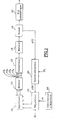
- an internal combustion engine 10 of the injection type produced by an injection device 26 comprises, for example, four cylinders of which the exhaust gases, materialized by the four arrows 10 1 , 10 2 , 10 3 and 10 4 , are collected in a collector 12 to be directed to a catalytic exhaust 24 preceded by a proportional probe 16.
- the element 14 materializes, functionally, a delay time e introduced by the length of the manifold 12 and corresponding to the transport time of the exhaust gases.
- the proportional type probe 16 provides a signal y (t), representing the richness of the exhaust gases, which is applied to a synchronization circuit 20 introducing a variable delay.
- the signal y (k) of output of synchronization circuit 20 is applied to a regulating device 22 which processes the signals of control of the injectors of the injection device 26 to from signal y (k) and a setpoint yc supplied by an injection computer 28 known by elsewhere.
- the signal y (t) is sampled (circuit 30) at a frequency fe plus higher than the engine U-turn, for example ten times, to create a signal y ( ⁇ ).
- This last signal is applied, on the one hand, to a device estimating delay 32 and, on the other hand, to a delay device variable 34 under the control of the estimating device delay which provides an estimated delay ê.
- T c is the duration of a motor cycle
- ê is the delay estimated by the device 32.
- the corrected signal is then resampled at the frequency of a half-turn of the motor (reference 36) to create the signal y (k).
- the estimator device 32 calculates the estimated delay ê between the measured signal y (r) and a model signal s (r).
- the model signal s ( ⁇ ) is a signal which is determined during the calibration of the synchronization device for a determined distribution of the wealth and for a known delay. It is in the form of a sample at the frequency fe, the values of which are recorded in a memory 38.
- the signal y ( ⁇ ) must correspond to the same distribution of the wealth as for s ( ⁇ ) and, for this purpose, the regulating device 22 is provided for introducing this distribution at times determined by a signal Sy.
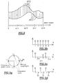
- the estimated delay is calculated, at each appearance of the signal Sy, using a synchronization algorithm seeking to minimize the area ⁇ (FIG. 2) between the measured signal y ( ⁇ ) and the model signal s (r) by shifting the signal s ( ⁇ ) by a value (T c -ê) which is then expressed by the formula: s (tT vs + ê).
- the determination of the minimum value of the area ⁇ is obtained by a gradient method.
- a gradient method is for example described in the book “SYSTEM IDENTIFICATION THEORY FOR THE USER “by Lennart Ljung published by PRENTICE-HALL Inc in 1987.
- This synchronization algorithm can be used from two different ways:
- the gradient is calculated after each engine cycle and it is used for the calculation of the next cycle. For converge, this way of doing things requires that the distribution profile and average wealth be constant over several cycles: this is the average of e over several cycles which is calculated.
- the signal y (k) is applied to the regulator 22.
- This regulator is of the rejection type disturbances, that is, it cancels the gas richness disturbances or variations exhaust due to a distribution of wealth individual cylinders.
- Figures 3a, 3b, 3c and 3d show a model of perturbation P (q) (figure 4) with three modes (q being the shift operator), two real modes and one mode complex.
- the three modes are located on the circle unit in order to be periodic.
- Real mode at 1 Figure 3b
- the second real mode -1 figure 3d
- the complex mode (+ i, -i) Figure 3c
- the three modes initialize with four initial conditions, which allows to have four different values on a cycle.
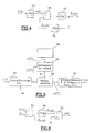
- the perturbation model is used for the synthesis of the disturbance rejection regulator.
- Point of start of the synthesis is figure 4 which shows the combination of the perturbation model P (q) (reference 40) with a model S (q) (reference 42) of mixing gas in the calculator and the application of a regulator R (q) (reference 44) to the combined model P (q) .S (q).
- a noise signal ⁇ (k) is applied to the input of the disturbance model P (q) and describes the modification of the periodic disturbance w (k) at over time.
- the periodic disturbance signal w (k) is applied to a comparator 46 which receives by elsewhere the output signal ⁇ u (k) of regulator 44.
- the difference signal provided by comparator 46 is applied to the gas mixture model S (q) which provides a deviation signal ⁇ y (k). This deviation signal constitutes the regulator input signal R (q).
- Rl (q), R2 (q) and P2 (q) are polynomials whose shift operator is q.
- the polynomial P2 (q) is the characteristic equation of the perturbation model.
- the modes of a dynamic model correspond to roots of its characteristic equation which determines its stability.
- a dynamic model is stable if its modes, represented in the complex plane, are at inside the complex unit circle.
- the regulator R (q) stabilizes the closed loop and cancels periodic disturbances if all modes controllable dynamic model corresponding to the closed loop are inside the unit circle.
- the controllable modes of the closed loop are those that can be modified by the choice of R (q).
- the trends uncontrollable closed loop are the ones that are invariants with respect to the choice of R (q). In the occurrence, they correspond to the modes of the model of disturbance included in the regulator.
- the diagram in Figure 6 shows part of the regulator 22 ( Figure 1) including a comparator 50 to compare the output signal y (k) of the synchronization 20 at setpoint signal yc. He gives the deviation signal ⁇ y (k) which is applied to the regulator 44 whose output signal ⁇ u (k) is added in an adder circuit 52 to the setpoint signal yc to give the injector control signal u (k).
- the four injector commands u1 (k), u2 (k), u3 (k) and u4 (k) are obtained by a device demultiplexing 60 of the signal u (k) as shown in the Figure 7. the demultiplexing device 60 ensures the update of the four injector controls at the motor cycle frequency.
- the commands u1 (k), u2 (k), u3 (k) and u4 (k) are applied respectively to the injectors 26 1 , 26 2 , 26 3 and 26 4 each associated with a cylinder of the engine 10.
- the summary calculations such regulators can be operated according to the LQG method (acronym for Linear Quadratic Gaussian) and Control Robust.
- LQG The first method called LQG is for example described in the book “COMPUTER CONTROLLED SYSTEMS” by Karl J. Aström and Björn Wittenmark edited by PRENTICE-HALL International Inc. in 1984.
- the second method is by example described in the book “ROBUST PROCESS CONTROL” by Manfred Morari and Evanghelos Zafiriou edited by PRENTICE-HALL Inc in 1989.
- Regulation of individual wealth of the mixture inlet in each of the engine cylinders in the called "regulation of individual wealth", is possible as long as the engine remains at the point of operation for which the delay ê has been identified. Each transition between two operating points requires a new identification of the delay ê, so ensure good synchronization of the regulator.
- Dispersions of injectors are manifested by the fact that an injector command applied to two injectors different provides two individual riches of different cylinder.
- the injector gain is quotient between individual cylinder richness and the injector control.
- the injector gains are identified during the regulation of individual wealth on the signal u (k).
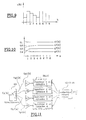
- the identification procedure is illustrated in Figure 8.
- An example of the input signal u (k) of the gain identification device is shown in Figure 9.
- the demultiplexing of u (k) gives four different signals u1 ( k), u2 (k), u3 (k) and u4 (k) corresponding to the injector commands.
- Each of the signals ul (k) to u4 (k) is then multiplied (multiplications 62 1 , 62 2 , 62 3 , 62 4 ) by 1 / u m , u m being the average over ul (k) at u4 (k) and then filtered by a low-pass filter (64 1 , 64 2 , 64 3 , 64 4 ).
- the four constants G1 to G4 correspond respectively to the inverses of the injector gains of cylinders 1 to 4.
- the commands ul (k), u2 (k), u3 (k) and u4 (k) ensure that the periodic gas richness disturbances engine exhaust are canceled.
- the signal u (k) supplied by the regulator is applied as shown in figure 7.
- a signal, Ug (k) provided by a wealth regulation medium is applied to demultiplexer 60 as shown in FIG. 11.
- the signal Ug (k) is demultiplexed for generate four injector commands Ug1 (k), Ug2 (k), Ug3 (k) and Ug4 (k). Before they are applied to injectors, they are respectively multiplied by the constants G1, G2, G3 and G4 in order to compensate for the injector gains.
Landscapes
- Engineering & Computer Science (AREA)
- Chemical & Material Sciences (AREA)
- Combustion & Propulsion (AREA)
- Mechanical Engineering (AREA)
- General Engineering & Computer Science (AREA)
- Electrical Control Of Air Or Fuel Supplied To Internal-Combustion Engine (AREA)
- Combined Controls Of Internal Combustion Engines (AREA)
Applications Claiming Priority (2)
| Application Number | Priority Date | Filing Date | Title |
|---|---|---|---|
| FR9805507 | 1998-04-30 | ||
| FR9805507A FR2778210B1 (fr) | 1998-04-30 | 1998-04-30 | Procede d'annulation des variations de richesse du melange gazeux issu des cylindres d'un moteur a combustion interne |
Publications (2)
| Publication Number | Publication Date |
|---|---|
| EP0953754A1 true EP0953754A1 (de) | 1999-11-03 |
| EP0953754B1 EP0953754B1 (de) | 2003-11-19 |
Family
ID=9525916
Family Applications (1)
| Application Number | Title | Priority Date | Filing Date |
|---|---|---|---|
| EP99400985A Expired - Lifetime EP0953754B1 (de) | 1998-04-30 | 1999-04-22 | Prozess zur Annullierung der Variationen des Reichtums der Gasmischung, die aus den Zylindern eines Verbrennungsmotors einer Maschine heraus fliesst |
Country Status (3)
| Country | Link |
|---|---|
| EP (1) | EP0953754B1 (de) |
| DE (1) | DE69912875T2 (de) |
| FR (1) | FR2778210B1 (de) |
Cited By (2)
| Publication number | Priority date | Publication date | Assignee | Title |
|---|---|---|---|---|
| EP1136684A3 (de) * | 2000-03-23 | 2003-04-02 | General Motors Corporation | Verfahren für zylinderindividuelle Kraftstoffregelung |
| FR2867230A1 (fr) * | 2004-03-05 | 2005-09-09 | Peugeot Citroen Automobiles Sa | Procede de controle d'un moteur a combustion interne |
Families Citing this family (1)
| Publication number | Priority date | Publication date | Assignee | Title |
|---|---|---|---|---|
| FR2817294B1 (fr) | 2000-11-27 | 2003-04-11 | Renault | Procede d'annulation des variations de richesse pour un moteur a allumage commande |
Citations (4)
| Publication number | Priority date | Publication date | Assignee | Title |
|---|---|---|---|---|
| US4962741A (en) * | 1989-07-14 | 1990-10-16 | Ford Motor Company | Individual cylinder air/fuel ratio feedback control system |
| EP0670420A2 (de) * | 1994-02-04 | 1995-09-06 | Honda Giken Kogyo Kabushiki Kaisha | System zur Abschätzung des Luft/Kraftstoffverhältnisses für eine Brennkraftmaschine |
| US5524598A (en) * | 1991-12-27 | 1996-06-11 | Honda Giken Kogyo Kabushiki Kaisha | Method for detecting and controlling air-fuel ratio in internal combustion engine |
| EP0719929A2 (de) * | 1994-12-30 | 1996-07-03 | Honda Giken Kogyo Kabushiki Kaisha | Regelungssystem für die Brennstoffdosierung eines Innenverbrennungsmotors |
Family Cites Families (1)
| Publication number | Priority date | Publication date | Assignee | Title |
|---|---|---|---|---|
| JPH01216047A (ja) * | 1988-02-24 | 1989-08-30 | Hitachi Ltd | エンジンの空燃比制御方法および装置 |
-
1998
- 1998-04-30 FR FR9805507A patent/FR2778210B1/fr not_active Expired - Fee Related
-
1999
- 1999-04-22 EP EP99400985A patent/EP0953754B1/de not_active Expired - Lifetime
- 1999-04-22 DE DE1999612875 patent/DE69912875T2/de not_active Expired - Lifetime
Patent Citations (4)
| Publication number | Priority date | Publication date | Assignee | Title |
|---|---|---|---|---|
| US4962741A (en) * | 1989-07-14 | 1990-10-16 | Ford Motor Company | Individual cylinder air/fuel ratio feedback control system |
| US5524598A (en) * | 1991-12-27 | 1996-06-11 | Honda Giken Kogyo Kabushiki Kaisha | Method for detecting and controlling air-fuel ratio in internal combustion engine |
| EP0670420A2 (de) * | 1994-02-04 | 1995-09-06 | Honda Giken Kogyo Kabushiki Kaisha | System zur Abschätzung des Luft/Kraftstoffverhältnisses für eine Brennkraftmaschine |
| EP0719929A2 (de) * | 1994-12-30 | 1996-07-03 | Honda Giken Kogyo Kabushiki Kaisha | Regelungssystem für die Brennstoffdosierung eines Innenverbrennungsmotors |
Cited By (2)
| Publication number | Priority date | Publication date | Assignee | Title |
|---|---|---|---|---|
| EP1136684A3 (de) * | 2000-03-23 | 2003-04-02 | General Motors Corporation | Verfahren für zylinderindividuelle Kraftstoffregelung |
| FR2867230A1 (fr) * | 2004-03-05 | 2005-09-09 | Peugeot Citroen Automobiles Sa | Procede de controle d'un moteur a combustion interne |
Also Published As
| Publication number | Publication date |
|---|---|
| DE69912875T2 (de) | 2004-11-11 |
| DE69912875D1 (de) | 2003-12-24 |
| EP0953754B1 (de) | 2003-11-19 |
| FR2778210B1 (fr) | 2000-12-15 |
| FR2778210A1 (fr) | 1999-11-05 |
Similar Documents
| Publication | Publication Date | Title |
|---|---|---|
| EP1049862B1 (de) | Vorrichtung zur abschätzung des luft/kraftstoffverhältnisses für ein kraftstoffeinspritzsystem einer brennkraftmaschine | |
| EP0953754B1 (de) | Prozess zur Annullierung der Variationen des Reichtums der Gasmischung, die aus den Zylindern eines Verbrennungsmotors einer Maschine heraus fliesst | |
| FR2567962A1 (fr) | Procede adaptatif de regulation de l'injection d'un moteur a injection | |
| EP1936156B1 (de) | Verfahren zur Steuerung eines Verbrennungsmotors | |
| EP1058781A1 (de) | Verfahren und einrichtung zum schnellen selbstanpassen des luft/kraftstoffverhältnisses in einer brennkraftmaschine | |
| FR2872221A1 (fr) | Procede de gestion d'un moteur a combustion interne | |
| EP1590562B1 (de) | Verfahren zur steuerung von zur ausführung der grundfunktionen eines verbrennungsmotors verwendeten elementen | |
| WO2016051044A1 (fr) | Moteur a combustion de véhicule automobile a pilotage de richesse améliore | |
| EP1760295B1 (de) | Regelvorrichtung für eine Diesel-Brennkraftmaschine mit Abgasrückführung | |
| EP0675277B1 (de) | Elektronisches System zur Berechnung der Kraftstoffeinspritzungsdauer | |
| FR3113270A1 (fr) | Détermination d’une contribution thermique et électrique d’un moteur hybride | |
| EP3215727B1 (de) | Verfahren zur vorhersage einer gaseinlassseitigen drosselklappe für die steuerung einer brennkraftmaschine | |
| FR2817294A1 (fr) | Procede d'annulation des variations de richesse pour un moteur a allumage commande | |
| EP1693559B1 (de) | Steuerungssystem zum Betreiben eines Dieselmotors mit Abgasrückführung | |
| EP1787020B1 (de) | System zur dieselmotorlaufsteuerung für ein kraftfahrzeug | |
| FR2740176A1 (fr) | Systeme et procede de double boucle de commande pour moteur a combustion interne | |
| FR2844306A1 (fr) | Procede et dispositif de commande d'un moteur a combustion interne | |
| FR2790516A1 (fr) | Procede de commande d'un moteur a combustion interne | |
| EP1957779B1 (de) | Verfahren zur steuerung eines kraftfahrzeugmotors zur einstellung der fettheit der luft-kraftstoff-mischung | |
| WO2022248782A1 (fr) | Procede de limitation d'une correction de parametre effectuee par plusieurs adaptatifs dans un controle moteur | |
| WO2023072565A1 (fr) | Procédé d'estimation de la pression atmosphérique pour un moteur à combustion interne | |
| FR2759415A1 (fr) | Procede de commande d'un moteur a combustion interne equipe d'un dispositif de recirculation des gaz d'echappement | |
| FR3085442A1 (fr) | Dispositif et procede de commande d’un moteur thermique de vehicule | |
| FR2862091A1 (fr) | Procede de regulation des variations de richesse pour un moteur diesel | |
| FR2980529A1 (fr) | Commande d'injection de carburant au demarrage d'un moteur thermique |
Legal Events
| Date | Code | Title | Description |
|---|---|---|---|
| PUAI | Public reference made under article 153(3) epc to a published international application that has entered the european phase |
Free format text: ORIGINAL CODE: 0009012 |
|
| AK | Designated contracting states |
Kind code of ref document: A1 Designated state(s): DE ES GB IT |
|
| AX | Request for extension of the european patent |
Free format text: AL;LT;LV;MK;RO;SI |
|
| 17P | Request for examination filed |
Effective date: 20000414 |
|
| AKX | Designation fees paid |
Free format text: DE ES GB IT |
|
| 17Q | First examination report despatched |
Effective date: 20011004 |
|
| RAP1 | Party data changed (applicant data changed or rights of an application transferred) |
Owner name: RENAULT S.A.S. |
|
| GRAH | Despatch of communication of intention to grant a patent |
Free format text: ORIGINAL CODE: EPIDOS IGRA |
|
| GRAS | Grant fee paid |
Free format text: ORIGINAL CODE: EPIDOSNIGR3 |
|
| GRAA | (expected) grant |
Free format text: ORIGINAL CODE: 0009210 |
|
| AK | Designated contracting states |
Kind code of ref document: B1 Designated state(s): DE ES GB IT |
|
| PG25 | Lapsed in a contracting state [announced via postgrant information from national office to epo] |
Ref country code: IT Free format text: LAPSE BECAUSE OF FAILURE TO SUBMIT A TRANSLATION OF THE DESCRIPTION OR TO PAY THE FEE WITHIN THE PRESCRIBED TIME-LIMIT;WARNING: LAPSES OF ITALIAN PATENTS WITH EFFECTIVE DATE BEFORE 2007 MAY HAVE OCCURRED AT ANY TIME BEFORE 2007. THE CORRECT EFFECTIVE DATE MAY BE DIFFERENT FROM THE ONE RECORDED. Effective date: 20031119 Ref country code: GB Free format text: LAPSE BECAUSE OF FAILURE TO SUBMIT A TRANSLATION OF THE DESCRIPTION OR TO PAY THE FEE WITHIN THE PRESCRIBED TIME-LIMIT Effective date: 20031119 |
|
| REG | Reference to a national code |
Ref country code: GB Ref legal event code: FG4D Free format text: NOT ENGLISH |
|
| REF | Corresponds to: |
Ref document number: 69912875 Country of ref document: DE Date of ref document: 20031224 Kind code of ref document: P |
|
| PG25 | Lapsed in a contracting state [announced via postgrant information from national office to epo] |
Ref country code: ES Free format text: LAPSE BECAUSE OF FAILURE TO SUBMIT A TRANSLATION OF THE DESCRIPTION OR TO PAY THE FEE WITHIN THE PRESCRIBED TIME-LIMIT Effective date: 20040302 |
|
| GBV | Gb: ep patent (uk) treated as always having been void in accordance with gb section 77(7)/1977 [no translation filed] |
Effective date: 20031119 |
|
| PLBE | No opposition filed within time limit |
Free format text: ORIGINAL CODE: 0009261 |
|
| STAA | Information on the status of an ep patent application or granted ep patent |
Free format text: STATUS: NO OPPOSITION FILED WITHIN TIME LIMIT |
|
| 26N | No opposition filed |
Effective date: 20040820 |
|
| PGFP | Annual fee paid to national office [announced via postgrant information from national office to epo] |
Ref country code: DE Payment date: 20150421 Year of fee payment: 17 |
|
| REG | Reference to a national code |
Ref country code: DE Ref legal event code: R119 Ref document number: 69912875 Country of ref document: DE |
|
| PG25 | Lapsed in a contracting state [announced via postgrant information from national office to epo] |
Ref country code: DE Free format text: LAPSE BECAUSE OF NON-PAYMENT OF DUE FEES Effective date: 20161101 |