EP0953407A1 - Powered oscillating hand tool - Google Patents
Powered oscillating hand tool Download PDFInfo
- Publication number
- EP0953407A1 EP0953407A1 EP99300371A EP99300371A EP0953407A1 EP 0953407 A1 EP0953407 A1 EP 0953407A1 EP 99300371 A EP99300371 A EP 99300371A EP 99300371 A EP99300371 A EP 99300371A EP 0953407 A1 EP0953407 A1 EP 0953407A1
- Authority
- EP
- European Patent Office
- Prior art keywords
- carrier plate
- platen
- drive shaft
- engagement means
- hand tool
- Prior art date
- Legal status (The legal status is an assumption and is not a legal conclusion. Google has not performed a legal analysis and makes no representation as to the accuracy of the status listed.)
- Granted
Links
Images

Classifications
-
- B—PERFORMING OPERATIONS; TRANSPORTING
- B24—GRINDING; POLISHING
- B24B—MACHINES, DEVICES, OR PROCESSES FOR GRINDING OR POLISHING; DRESSING OR CONDITIONING OF ABRADING SURFACES; FEEDING OF GRINDING, POLISHING, OR LAPPING AGENTS
- B24B23/00—Portable grinding machines, e.g. hand-guided; Accessories therefor
- B24B23/04—Portable grinding machines, e.g. hand-guided; Accessories therefor with oscillating grinding tools; Accessories therefor
-
- B—PERFORMING OPERATIONS; TRANSPORTING
- B24—GRINDING; POLISHING
- B24B—MACHINES, DEVICES, OR PROCESSES FOR GRINDING OR POLISHING; DRESSING OR CONDITIONING OF ABRADING SURFACES; FEEDING OF GRINDING, POLISHING, OR LAPPING AGENTS
- B24B23/00—Portable grinding machines, e.g. hand-guided; Accessories therefor
- B24B23/02—Portable grinding machines, e.g. hand-guided; Accessories therefor with rotating grinding tools; Accessories therefor
- B24B23/03—Portable grinding machines, e.g. hand-guided; Accessories therefor with rotating grinding tools; Accessories therefor the tool being driven in a combined movement
Definitions
- the present invention relates to a powered oscillating hand tool, in particular a powered oscillating hand tool comprising a drive unit having an electric motor with a drive shaft to which a sander head can be attached.
- the drive system comprises an eccentric which is restrained so that the sander shoe cannot spin independently of the motor and it therefore describes a regular orbit.
- the shoes of such sanders are available in a range of shapes and such sanders are in general used for the removal of relatively small quantities of material, for example for detailed work or for finishing.
- the base of the shoe may be provided with a surface, in particular a hook and loop surface, on which an abrasive sheet may be mounted.
- European Patent No 610 801 describes a sander which carries a triangular shoe which can be detached from the body of the sander by means of an operating button located at the front corner of the sander.
- the operating button carries a bolt which is resiliently mounted on the tool and is biased towards engagement under a catch hook provided in the triangular shoe.
- the sander is further provided, on the edge opposite the operating button, with at least one engagement opening for engaging at least one support claw provided on the triangular shoe.
- the present invention therefore provides a powered oscillating hand tool comprising
- the first and second engagement means preferably together form a bayonet fitting, more preferably a bayonet fitting of the type in which the first engagement means (provided on the carrier) is in the form of one or more apertures and the second engagement means is in the form of one or more hook members.
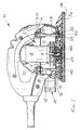
- FIG 1 shows a sanding device (10) comprising a drive unit (2) including an electric motor (4) located in a housing (6) and a drive shaft (8).
- a fan (12) mounted on shaft (8) is arranged to draw air in from mouth (14) of a carrier plate (16) permanently mounted to the sanding device (10) and direct it through extractor duct (18) to exhaust outlet (20).
- a nut is used to secure the carrier plate (16) (see Figure 2) to a second drive shaft (24) which is housed in the fan (12) by bearing (26) which is eccentrically located radially in respect to shaft (8).
- Three flexible columns (28) made of rubber are arranged around the drive shaft (8).
- the upper end (30) of each of the flexible columns (28) is held in the housing (6) and the lower end (32) is located in a recess (34) provided in the carrier plate (16).
- a platen (36) is detachably mounted on the carrier plate (16), as will be described in more detail with reference to Figures 2, 3 and 4.
- the platen (36) is driven by the electric motor (4) through shafts (8,24).
- a perforated sandpaper sheet (not shown) may be attached to the outer face (38) of the platen (36), for example by the use of hook-and-loop fabric such as that sold as VELCRO (RTM) glued to face (38).
- Holes (40) passing through the platen (36) facilitate the removal of dust etc., from the sanding face through the platen (36) to exhaust outlet (20) via the duct (18).
- An extractor hose (not shown) may be attached to the exhaust outlet (20).
- the carrier plate (16) is made from a plastics material, for example glass filled nylon and carries on its underside a plurality of strengthening ribs (not shown).
- the carrier plate (16) includes three recesses (34) which are used to couple the carrier plate (16) to the sanding device (10) by means of the flexible columns (28) which locate in the recesses (34) in known manner.
- the centre of the carrier plate (16) has a boss (42) which is used to accept the eccentrically mounted second drive shaft (24).
- the carrier plate (16) has a plurality of holes (44) formed therein and spaced at 120° around the central boss (42).
- the holes (44) are formed so that each can accept one of a plurality of projections formed on the platen (36) which will be described in more detail below.
- the holes (44) are shaped so as to provide an area of relatively large cross sectional area which narrows down to a strip of narrow width. Flanking each hole (44) and extending substantially along the length from the relatively large cross-sectional area to the end of the relatively narrow strip is a further hole (46).
- These holes (46) are formed so as to allow the piece of plastics material (48) from which the carrier plate (16) is formed and which is situated between the holes (44) and (46) to act as a spring mechanism.
- the hole (44) is shaped so that an inwardly projecting piece (50) of the plastics material of the carrier plate (16) is formed at the position shown.
- each hole (44) is associated with a vertically displaced cover member (52).
- the platen (36) is provided with a plurality of projections (54) projecting from the inner face of the platen (36).
- the platen (36) In order to mount the platen (36) on the carrier plate (16) the platen (36) is oriented such that projections (54) are situated directly below each of the holes (44). The platen (36) is then urged toward the carrier plate (16) so that the projections (54) protrude through their respective holes (44).
- each projection (54) has a portion (56) formed as a flat face.
- this portion (56) lies flat against a face (58) of the carrier plate (16). This is necessary so that the majority of the oscillating driving force is imparted to platen (36) by the carrier plate (16) through these flat and abutting faces (56), (58).
- the platen (36) is retained from separating and therefore falling off the carrier plate (16) by way of hook (60) shown in Figure 3 co-operating with the cover member (52).
- the cover member (52) is situated in a plane which is vertically displaced from the plane of the carrier plate (16) and standing proud thereof. The hook (60) therefore sits between the cover member (52) and the plane of the carrier plate (16) and in this way the cover member (52) acts as a catch for the hook (60).
- the platen (36) In order to prevent the tip portion of the platen (36) coming away from the carrier plate (16) the platen (36) carries a first ramp surface (62) as shown in Figure 3, which ramp surface (62) co-operates with a second ramp surface (64) in the carrier plate (16). It will be understood that the coupling mechanism between the first ramp surface (62) and second ramp surface (64) operates to engage the two surfaces, when the platen is rotated to engage the projection (54) and its hook (60).
- One more alternative platen (36) can be provided, for use in different sanding operations, such as for detail sanding, sanding louvres, where the platen is provided with a finger extension and contour sanding.
Landscapes
- Engineering & Computer Science (AREA)
- Mechanical Engineering (AREA)
- Finish Polishing, Edge Sharpening, And Grinding By Specific Grinding Devices (AREA)
- Lubricants (AREA)
- Massaging Devices (AREA)
- Knives (AREA)
Abstract
Description
- The present invention relates to a powered oscillating hand tool, in particular a powered oscillating hand tool comprising a drive unit having an electric motor with a drive shaft to which a sander head can be attached.
- In conventional sanders of the orbital type, with a shaped shoe, the drive system comprises an eccentric which is restrained so that the sander shoe cannot spin independently of the motor and it therefore describes a regular orbit. The shoes of such sanders are available in a range of shapes and such sanders are in general used for the removal of relatively small quantities of material, for example for detailed work or for finishing. The base of the shoe may be provided with a surface, in particular a hook and loop surface, on which an abrasive sheet may be mounted.
- European Patent No 610 801 describes a sander which carries a triangular shoe which can be detached from the body of the sander by means of an operating button located at the front corner of the sander. The operating button carries a bolt which is resiliently mounted on the tool and is biased towards engagement under a catch hook provided in the triangular shoe. The sander is further provided, on the edge opposite the operating button, with at least one engagement opening for engaging at least one support claw provided on the triangular shoe.
- It is a disadvantage of such an arrangement that it is expensive to manufacture and may be difficult to operate to attach and detach the shoe, in particular under the conditions in which the sander is likely to be used.
- It is an object of the present invention to provide a sander in which the above disadvantages are reduced or substantially obviated.
- The present invention therefore provides a powered oscillating hand tool comprising
- (a) a drive unit having an electric motor and a drive shaft;
- (b) a bearing mounted on the drive shaft and located radially eccentrically relative to the drive shaft;
- (c) a second drive shaft mounted on the eccentric bearing;
- (d) a carrier plate mounted on the second drive shaft and
- (e) a platen for mounting on the carrier plate characterised in that the carrier plate is provided with a first engagement means and the platen is provided with second engagement means to engage with the first engagement means by rotation of the platen relative to the carrier plate.
-
- The first and second engagement means preferably together form a bayonet fitting, more preferably a bayonet fitting of the type in which the first engagement means (provided on the carrier) is in the form of one or more apertures and the second engagement means is in the form of one or more hook members.
- An embodiment of a powered oscillating hand tool according to the invention will now be described with reference to the accompanying drawings in which
- Figure 1 is a side view, in section of a preferred embodiment of a powered oscillating hand tool according to the invention, with a platen attached;
- Figure 2 is a perspective view of the carrier plate of Figure 1, viewed from above, and
- Figure 3 is a perspective view of the platen of Figure 1, viewed from above.
-
- Figure 1 shows a sanding device (10) comprising a drive unit (2) including an electric motor (4) located in a housing (6) and a drive shaft (8). A fan (12) mounted on shaft (8) is arranged to draw air in from mouth (14) of a carrier plate (16) permanently mounted to the sanding device (10) and direct it through extractor duct (18) to exhaust outlet (20). A nut is used to secure the carrier plate (16) (see Figure 2) to a second drive shaft (24) which is housed in the fan (12) by bearing (26) which is eccentrically located radially in respect to shaft (8).
- Three flexible columns (28) made of rubber are arranged around the drive shaft (8). The upper end (30) of each of the flexible columns (28) is held in the housing (6) and the lower end (32) is located in a recess (34) provided in the carrier plate (16).
- A platen (36) is detachably mounted on the carrier plate (16), as will be described in more detail with reference to Figures 2, 3 and 4.
- The platen (36) is driven by the electric motor (4) through shafts (8,24). A perforated sandpaper sheet (not shown) may be attached to the outer face (38) of the platen (36), for example by the use of hook-and-loop fabric such as that sold as VELCRO (RTM) glued to face (38). Holes (40) passing through the platen (36) facilitate the removal of dust etc., from the sanding face through the platen (36) to exhaust outlet (20) via the duct (18). An extractor hose (not shown) may be attached to the exhaust outlet (20).
- As can be seen from Figure 2, the carrier plate (16) is made from a plastics material, for example glass filled nylon and carries on its underside a plurality of strengthening ribs (not shown). The carrier plate (16) includes three recesses (34) which are used to couple the carrier plate (16) to the sanding device (10) by means of the flexible columns (28) which locate in the recesses (34) in known manner. The centre of the carrier plate (16) has a boss (42) which is used to accept the eccentrically mounted second drive shaft (24).
- The carrier plate (16) has a plurality of holes (44) formed therein and spaced at 120° around the central boss (42). The holes (44) are formed so that each can accept one of a plurality of projections formed on the platen (36) which will be described in more detail below. The holes (44) are shaped so as to provide an area of relatively large cross sectional area which narrows down to a strip of narrow width. Flanking each hole (44) and extending substantially along the length from the relatively large cross-sectional area to the end of the relatively narrow strip is a further hole (46). These holes (46) are formed so as to allow the piece of plastics material (48) from which the carrier plate (16) is formed and which is situated between the holes (44) and (46) to act as a spring mechanism. The hole (44) is shaped so that an inwardly projecting piece (50) of the plastics material of the carrier plate (16) is formed at the position shown.
- It will also be seen from Figure 2 that each hole (44) is associated with a vertically displaced cover member (52).
- The platen (36) is provided with a plurality of projections (54) projecting from the inner face of the platen (36). In order to mount the platen (36) on the carrier plate (16) the platen (36) is oriented such that projections (54) are situated directly below each of the holes (44). The platen (36) is then urged toward the carrier plate (16) so that the projections (54) protrude through their respective holes (44). As can be seen from the relative orientation of each of the projections (54) and holes (44), when the platen (36) is rotated by approximately 24° then the outer peripheral shapes of the platen (36) and carrier plate (16) coincide and also the projections (54) are rotated about the boss (42) such that they are held within the holes (44) by way of the projection (50) acting as a detent and also the strip of material (48) of the carrier plate (16) between the holes (44) and (46) acting as a spring urging this detent into engagement with each projection (54). As can be seen in particular from Figures 3 and 4, each projection (54) has a portion (56) formed as a flat face. When the platen (36) and carrier plate (16) are rotated so as to be locked together as described above, this portion (56) lies flat against a face (58) of the carrier plate (16). This is necessary so that the majority of the oscillating driving force is imparted to platen (36) by the carrier plate (16) through these flat and abutting faces (56), (58). The platen (36) is retained from separating and therefore falling off the carrier plate (16) by way of hook (60) shown in Figure 3 co-operating with the cover member (52). As has been described above, the cover member (52) is situated in a plane which is vertically displaced from the plane of the carrier plate (16) and standing proud thereof. The hook (60) therefore sits between the cover member (52) and the plane of the carrier plate (16) and in this way the cover member (52) acts as a catch for the hook (60).
- In order to prevent the tip portion of the platen (36) coming away from the carrier plate (16) the platen (36) carries a first ramp surface (62) as shown in Figure 3, which ramp surface (62) co-operates with a second ramp surface (64) in the carrier plate (16). It will be understood that the coupling mechanism between the first ramp surface (62) and second ramp surface (64) operates to engage the two surfaces, when the platen is rotated to engage the projection (54) and its hook (60).
- One more alternative platen (36) can be provided, for use in different sanding operations, such as for detail sanding, sanding louvres, where the platen is provided with a finger extension and contour sanding.
Claims (5)
- A powered oscillating hand tool (10) comprising(a) a drive unit (2) having an electric motor (4) and a drive shaft (6);(b) a bearing (26) mounted on the drive shaft (8) and located radially eccentrically relative to the drive shaft (8);(c) a second drive shaft (24) mounted on the eccentric bearing (26) ;(d) a carrier plate (16) mounted on the second drive shaft (24) and(e) a platen (36) for mounting on the carrier plate (16) characterised in that the carrier plate (16) is provided with a first engagement means (44) and the platen is provided with second engagement means (54) to engage with the first engagement means (44) by rotation of the platen (36) relative to the carrier plate (16).
- A powered oscillating hand tool according to claim 1, characterised in that the first and second engagement means together comprise a bayonet fitting.
- A powered oscillating hand tool according to claim 2, characterised in that the first engagement means comprises one or more apertures and the second engagement means comprises one or more hook members.
- A powered oscillating hand tool according to any of claims 1 to 3 which is a sander.
- A powered oscillating hand tool substantially as herein described and with reference to the accompanying drawings.
Applications Claiming Priority (2)
| Application Number | Priority Date | Filing Date | Title |
|---|---|---|---|
| GBGB9809030.1A GB9809030D0 (en) | 1998-04-29 | 1998-04-29 | Powered oscillating hand tool |
| GB9809030 | 1998-04-29 |
Publications (2)
| Publication Number | Publication Date |
|---|---|
| EP0953407A1 true EP0953407A1 (en) | 1999-11-03 |
| EP0953407B1 EP0953407B1 (en) | 2002-06-05 |
Family
ID=10831098
Family Applications (1)
| Application Number | Title | Priority Date | Filing Date |
|---|---|---|---|
| EP99300371A Expired - Lifetime EP0953407B1 (en) | 1998-04-29 | 1999-01-19 | Powered oscillating hand tool |
Country Status (7)
| Country | Link |
|---|---|
| US (2) | US6179696B1 (en) |
| EP (1) | EP0953407B1 (en) |
| CN (1) | CN1094086C (en) |
| AT (1) | ATE218412T1 (en) |
| DE (1) | DE69901653D1 (en) |
| GB (1) | GB9809030D0 (en) |
| HK (1) | HK1020904A1 (en) |
Cited By (6)
| Publication number | Priority date | Publication date | Assignee | Title |
|---|---|---|---|---|
| EP1277544A2 (en) * | 2001-07-20 | 2003-01-22 | Black & Decker Inc. | Oscillating hand tool |
| EP1277543A2 (en) * | 2001-07-20 | 2003-01-22 | Black & Decker Inc. | Oscillating hand tool |
| EP1612002A1 (en) * | 2004-07-02 | 2006-01-04 | BLACK & DECKER INC. | Power tool |
| US7052383B2 (en) | 2001-12-07 | 2006-05-30 | Robert Bosch Gmbh | Manual orbital sander |
| DE10306974B4 (en) * | 2003-02-19 | 2006-11-23 | Kompernaß Handelsgesellschaft mbH | Hand sander |
| NL1030176C2 (en) * | 2005-10-12 | 2007-04-17 | Bosch Gmbh Robert | Hand tools with improved drive. |
Families Citing this family (26)
| Publication number | Priority date | Publication date | Assignee | Title |
|---|---|---|---|---|
| DE10047543A1 (en) * | 2000-09-22 | 2002-04-11 | Bosch Gmbh Robert | Abrasives and abrasives for an electrical grinding tool and electrical grinding tool |
| US6814656B2 (en) * | 2001-03-20 | 2004-11-09 | Luis J. Rodriguez | Surface treatment disks for rotary tools |
| US6758731B2 (en) * | 2001-08-10 | 2004-07-06 | One World Technologies Limited | Orbital sander |
| WO2004049886A2 (en) * | 2002-12-03 | 2004-06-17 | S. C. Johnson & Son, Inc. | P0wered cleaner/polisher |
| US6799579B2 (en) * | 2003-01-29 | 2004-10-05 | James R. Joseph | Fingernail and toenail shaping apparatus |
| US7565712B2 (en) * | 2003-11-26 | 2009-07-28 | S.C. Johnson & Son, Inc. | Powered cleaner/polisher |
| DE102004016015A1 (en) * | 2004-04-01 | 2005-10-20 | Bosch Gmbh Robert | Hand-guided grinding machine, grinding machine holding unit and grinding machine housing |
| US20050221738A1 (en) * | 2004-04-06 | 2005-10-06 | Cooper Vincent P | Orbital sander with vertical handle |
| DE102004047811A1 (en) * | 2004-09-29 | 2006-03-30 | Robert Bosch Gmbh | Grinding hand tool machine, in particular Akkuschleifhandwerkzeugmaschine |
| DE102004047808A1 (en) * | 2004-09-29 | 2006-03-30 | Robert Bosch Gmbh | Grinding hand tool machine, in particular Akkuschleifhandwerkzeugmaschine |
| CA2529354A1 (en) * | 2005-12-08 | 2007-06-08 | Luigi Panfili | Sanding device, system including the same, and method of operating associated thereto |
| US20090004953A1 (en) * | 2007-06-27 | 2009-01-01 | Kinsey Verla M | Skin sander |
| US8172642B2 (en) | 2008-08-20 | 2012-05-08 | Black & Decker Inc. | Multi-sander |
| DE102010003616A1 (en) | 2010-04-01 | 2011-10-06 | Robert Bosch Gmbh | Holding body for flexible abrasive and grinding system |
| US9421682B2 (en) | 2011-07-18 | 2016-08-23 | Black & Decker Inc. | Multi-head power tool with reverse lock-out capability |
| US10130229B2 (en) * | 2013-03-28 | 2018-11-20 | Yale Merret Smith | Efficient surface treating machine |
| US9956677B2 (en) | 2013-05-08 | 2018-05-01 | Black & Decker Inc. | Power tool with interchangeable power heads |
| DE102013106546A1 (en) * | 2013-06-24 | 2014-12-24 | C. & E. Fein Gmbh | Sanding pad for an oscillation drive |
| CN103331676A (en) * | 2013-07-03 | 2013-10-02 | 南通普乐工具有限公司 | Machine head regulating device of triangular sander |
| US9387578B2 (en) * | 2013-10-28 | 2016-07-12 | Black & Decker Inc. | Handle arrangement for sander |
| WO2015077988A1 (en) | 2013-11-29 | 2015-06-04 | Black & Decker Inc. | Sander having two-piece fan |
| US10076819B2 (en) | 2014-05-15 | 2018-09-18 | Barry ULRICH | Sandpaper sheet for use with tools configured for dust extraction |
| CN105328527A (en) * | 2015-11-16 | 2016-02-17 | 邓泽雄 | Driving device for polishing machine |
| CN108067985B (en) * | 2016-11-08 | 2023-11-07 | 苏州宝时得电动工具有限公司 | Sanding machine |
| USD863913S1 (en) * | 2018-05-23 | 2019-10-22 | Zhuhai Sharp-Group Enterprise Co., Ltd. | Triangular sander |
| USD900573S1 (en) * | 2019-05-06 | 2020-11-03 | Shenzhen Aukeyhi Technology co., Ltd. | Sander |
Citations (3)
| Publication number | Priority date | Publication date | Assignee | Title |
|---|---|---|---|---|
| DE3512190A1 (en) * | 1985-04-03 | 1986-10-09 | Licentia Patent-Verwaltungs-Gmbh, 6000 Frankfurt | Grinding or brushing unit which is driven by an electric motor |
| EP0610801A1 (en) * | 1993-02-04 | 1994-08-17 | Robert Bosch Gmbh | Handtool for machining surfaces |
| DE29614325U1 (en) * | 1996-08-21 | 1996-10-31 | Kress-Elektrik GmbH & Co Elektromotorenfabrik, 72406 Bisingen | Hand tool for surface processing |
Family Cites Families (43)
| Publication number | Priority date | Publication date | Assignee | Title |
|---|---|---|---|---|
| CA707935A (en) | 1965-04-20 | Joseph H. Mackay, Jr. | Finishing article holder and support pad | |
| DE620782C (en) | 1935-10-26 | Ludwig Roemer | Transportable, electrically driven wood sanding machine with sanding pad | |
| GB602431A (en) | 1945-04-06 | 1948-05-26 | Titan Abrasive Company | Improvements in or relating to abrasive disc devices and assemblies |
| US2893177A (en) * | 1958-11-19 | 1959-07-07 | American Lincoln Corp | Surfacing machine |
| US3345784A (en) * | 1964-12-29 | 1967-10-10 | Rockwell Mfg Co | Orbital finishing sander |
| DE1502526C3 (en) | 1965-07-17 | 1978-04-13 | Merit Products Inc., Los Angeles, Calif. (V.St.A.) | Grinding wheel attachment |
| DE1652152A1 (en) | 1967-02-04 | 1970-05-06 | Relu Gebr Seitz Ohg | Hand surface grinding machine, so-called slipper |
| IT943563B (en) | 1970-11-04 | 1973-04-10 | Mafell Maschinenfabrik Mey R K | SANDER IN PARTICULAR HONED RE WITH VIBRATING TOOL WITH VENTS AND VACUUM CLEANER |
| GB1364025A (en) | 1971-10-01 | 1974-08-21 | Stoll Kg Kurt | Hand grinders |
| US3849943A (en) * | 1973-02-26 | 1974-11-26 | Rockwell International Corp | Power operated sanding machine |
| US3864884A (en) | 1973-09-14 | 1975-02-11 | Bernard Weissman | Abrading tool and holder therefor |
| DE2907930C2 (en) | 1979-03-01 | 1982-12-16 | Festo-Maschinenfabrik Gottlieb Stoll, 7300 Esslingen | Pneumatic hand grinder |
| GB2084059A (en) | 1980-10-01 | 1982-04-07 | Mcgarry Iain | Sanding attachment for a power tool |
| JPS607953U (en) | 1983-06-27 | 1985-01-19 | リョービ株式会社 | sander dust collector |
| US4475317A (en) | 1983-11-28 | 1984-10-09 | The Singer Company | Paper retainer for a sanding device |
| IT8520537V0 (en) | 1985-01-18 | 1985-01-18 | Valentini Guido | PORTABLE ELECTRIC MACHINE TOOL MACHINE FOR THE PROCESSING OF SURFACES OF MATERIALS WITH AMPLIFIED ASPIRATION OF THE DUST PRODUCED. |
| US4716368A (en) * | 1985-08-09 | 1987-12-29 | Picker International, Inc. | Magnetic resonance reconstruction and scanning techniques using known information, constraints, and symmetry relations |
| EP0244465B1 (en) | 1985-11-15 | 1989-08-02 | C. & E. FEIN GmbH & Co. | Portable grinder |
| US5123216A (en) | 1985-11-15 | 1992-06-23 | C. & E. Fein Gmbh & Co. | Portable grinder |
| USD310007S (en) * | 1987-05-21 | 1990-08-21 | Ryobi Ltd. | Portable electric sander |
| EP0333933B1 (en) | 1988-03-22 | 1993-09-15 | Maeda Kiko Company Limited | Sanding apparatus |
| DE3840974A1 (en) | 1988-12-06 | 1990-06-07 | Fein C & E | OSCILLATION DRIVE |
| USD326398S (en) * | 1989-05-23 | 1992-05-26 | Makita Electric Works, Ltd. | Orbital sander |
| USD332734S (en) * | 1989-10-24 | 1993-01-26 | Makita Electric Works, Ltd. | Polisher |
| DE4011761A1 (en) | 1990-04-11 | 1991-10-17 | Tentec Gmbh Werkzeuge Maschine | Orbital sander with exchangeable tools - which have backplate with bracket keying into guides on machine drive plate |
| DE4040578A1 (en) * | 1990-12-19 | 1992-07-02 | Bosch Gmbh Robert | ORBITAL GRINDERS |
| DE4118392B4 (en) | 1991-06-05 | 2010-03-18 | Robert Bosch Gmbh | Random Orbit Sander |
| DE4223107A1 (en) | 1992-07-14 | 1994-01-20 | Bosch Gmbh Robert | Surface grinding machine |
| DE4233727A1 (en) * | 1992-10-07 | 1994-04-14 | Bosch Gmbh Robert | Eccentric disc grinder |
| EP0710527B1 (en) | 1993-02-04 | 2003-10-22 | Robert Bosch Gmbh | Handtool for machining surfaces |
| DE4311869C2 (en) | 1993-04-10 | 1995-10-12 | Laegler Eugen Gmbh | Tillage machine |
| US5637034A (en) * | 1993-08-13 | 1997-06-10 | Ryobi North America, Inc. | Detail sander |
| US5470272A (en) | 1994-02-03 | 1995-11-28 | Ryobi Motor Products Corp. | Removable working tool assembly |
| US5554066A (en) | 1995-02-09 | 1996-09-10 | Proter-Cable Corporation | In-line profile sander |
| US5597347A (en) | 1995-02-09 | 1997-01-28 | Porter-Cable Corporation | Sander vacuum housing and pad frame system |
| US5709596A (en) * | 1996-01-22 | 1998-01-20 | Ryobi North America | Ergonomically profiled hand grip for a hand-held tool having a pivotable pommel |
| USD380950S (en) * | 1996-01-22 | 1997-07-15 | Black & Decker Inc. | Polisher housing |
| USD386376S (en) * | 1996-02-23 | 1997-11-18 | Makita Corporation | Sander |
| JP3316622B2 (en) * | 1996-03-08 | 2002-08-19 | 株式会社マキタ | Sanda |
| USD404273S (en) | 1997-01-13 | 1999-01-19 | Black & Decker Inc. | Detail sander |
| USD392861S (en) * | 1997-04-28 | 1998-03-31 | Black & Decker Inc. | Palm grip sander |
| USD408245S (en) * | 1998-03-06 | 1999-04-20 | Black & Decker Inc. | Sheet sander |
| USD447397S1 (en) * | 2000-10-16 | 2001-09-04 | Black & Decker Inc. | Sander |
-
1998
- 1998-04-29 GB GBGB9809030.1A patent/GB9809030D0/en not_active Ceased
-
1999
- 1999-01-19 EP EP99300371A patent/EP0953407B1/en not_active Expired - Lifetime
- 1999-01-19 AT AT99300371T patent/ATE218412T1/en not_active IP Right Cessation
- 1999-01-19 DE DE69901653T patent/DE69901653D1/en not_active Expired - Lifetime
- 1999-04-23 US US09/298,579 patent/US6179696B1/en not_active Ceased
- 1999-04-28 CN CN99106145A patent/CN1094086C/en not_active Expired - Fee Related
- 1999-12-30 HK HK99106202A patent/HK1020904A1/en not_active IP Right Cessation
-
2002
- 2002-09-06 US US10/122,747 patent/USRE40345E1/en not_active Expired - Lifetime
Patent Citations (3)
| Publication number | Priority date | Publication date | Assignee | Title |
|---|---|---|---|---|
| DE3512190A1 (en) * | 1985-04-03 | 1986-10-09 | Licentia Patent-Verwaltungs-Gmbh, 6000 Frankfurt | Grinding or brushing unit which is driven by an electric motor |
| EP0610801A1 (en) * | 1993-02-04 | 1994-08-17 | Robert Bosch Gmbh | Handtool for machining surfaces |
| DE29614325U1 (en) * | 1996-08-21 | 1996-10-31 | Kress-Elektrik GmbH & Co Elektromotorenfabrik, 72406 Bisingen | Hand tool for surface processing |
Cited By (10)
| Publication number | Priority date | Publication date | Assignee | Title |
|---|---|---|---|---|
| EP1277544A2 (en) * | 2001-07-20 | 2003-01-22 | Black & Decker Inc. | Oscillating hand tool |
| EP1277543A2 (en) * | 2001-07-20 | 2003-01-22 | Black & Decker Inc. | Oscillating hand tool |
| EP1277544A3 (en) * | 2001-07-20 | 2004-01-28 | Black & Decker Inc. | Oscillating hand tool |
| EP1277543A3 (en) * | 2001-07-20 | 2004-01-28 | Black & Decker Inc. | Oscillating hand tool |
| AU2002300030B2 (en) * | 2001-07-20 | 2008-04-10 | Black And Decker, Inc. | Oscillating hand tool |
| US7052383B2 (en) | 2001-12-07 | 2006-05-30 | Robert Bosch Gmbh | Manual orbital sander |
| DE10306974B4 (en) * | 2003-02-19 | 2006-11-23 | Kompernaß Handelsgesellschaft mbH | Hand sander |
| EP1612002A1 (en) * | 2004-07-02 | 2006-01-04 | BLACK & DECKER INC. | Power tool |
| NL1030176C2 (en) * | 2005-10-12 | 2007-04-17 | Bosch Gmbh Robert | Hand tools with improved drive. |
| WO2007043871A1 (en) * | 2005-10-12 | 2007-04-19 | Robert Bosch Gmbh | Hand tool with improved drive |
Also Published As
| Publication number | Publication date |
|---|---|
| EP0953407B1 (en) | 2002-06-05 |
| CN1233549A (en) | 1999-11-03 |
| HK1020904A1 (en) | 2000-05-26 |
| US6179696B1 (en) | 2001-01-30 |
| CN1094086C (en) | 2002-11-13 |
| USRE40345E1 (en) | 2008-05-27 |
| GB9809030D0 (en) | 1998-06-24 |
| ATE218412T1 (en) | 2002-06-15 |
| DE69901653D1 (en) | 2002-07-11 |
Similar Documents
| Publication | Publication Date | Title |
|---|---|---|
| EP0953407A1 (en) | Powered oscillating hand tool | |
| EP0694365B1 (en) | Improved oscillating hand tool | |
| US10906155B2 (en) | Power tool with interchangeable tool head | |
| US5609516A (en) | Rotating abrader with polygonal pad and dust evacuation | |
| US5709595A (en) | Power tool for surface treatment | |
| US8007346B2 (en) | Electric hand-held power tool for performing sanding work, in particular a finishing sander | |
| US4616449A (en) | Suction housing for vacuum sanding devices | |
| US5885146A (en) | Oscillating hand tool | |
| SE446317B (en) | CONTROL DEVICE FOR REGULATING THE GRADE OF REPRESENT ALSTRATE IN A SUCCESS TO A SURFACE APPLIANCE | |
| EP1277543B1 (en) | Oscillating hand tool | |
| EP0141139B1 (en) | Suction housing for vacuum sanding devices | |
| US6857949B2 (en) | Electric portable grinding machine, particularly an eccentric grinder, provided with edge protection | |
| KR101220750B1 (en) | Dust Hood Assembly for Adjusting Location Easily and Power Tool with the Same | |
| EP0719616B1 (en) | Improved oscillating hand tool | |
| CN212553186U (en) | Polishing device | |
| GB2408710A (en) | Attaching an abrasive sheet to a backing plate using suction | |
| CN110877267B (en) | Back lining, track sanding or polishing machine and sheet-like sanding or polishing member | |
| EP2636483A1 (en) | Hand-held machine tool for sanding, grinding or polishing a workpiece | |
| JP4377662B2 (en) | Belt grinding tool | |
| US20240278370A1 (en) | Dust bag for power tool and power tool | |
| JPH0646857U (en) | Portable polishing device | |
| JPH0247169U (en) |
Legal Events
| Date | Code | Title | Description |
|---|---|---|---|
| PUAI | Public reference made under article 153(3) epc to a published international application that has entered the european phase |
Free format text: ORIGINAL CODE: 0009012 |
|
| 17P | Request for examination filed |
Effective date: 19990128 |
|
| AK | Designated contracting states |
Kind code of ref document: A1 Designated state(s): AT BE CH DE DK ES FI FR GB IE IT LI LU MC NL PT SE |
|
| AX | Request for extension of the european patent |
Free format text: AL;LT;LV;MK;RO;SI |
|
| AKX | Designation fees paid |
Free format text: AT BE CH DE DK ES FI FR GB IE IT LI LU MC NL PT SE |
|
| 17Q | First examination report despatched |
Effective date: 20000623 |
|
| GRAG | Despatch of communication of intention to grant |
Free format text: ORIGINAL CODE: EPIDOS AGRA |
|
| GRAG | Despatch of communication of intention to grant |
Free format text: ORIGINAL CODE: EPIDOS AGRA |
|
| GRAG | Despatch of communication of intention to grant |
Free format text: ORIGINAL CODE: EPIDOS AGRA |
|
| GRAH | Despatch of communication of intention to grant a patent |
Free format text: ORIGINAL CODE: EPIDOS IGRA |
|
| GRAH | Despatch of communication of intention to grant a patent |
Free format text: ORIGINAL CODE: EPIDOS IGRA |
|
| GRAA | (expected) grant |
Free format text: ORIGINAL CODE: 0009210 |
|
| AK | Designated contracting states |
Kind code of ref document: B1 Designated state(s): AT BE CH DE DK ES FI FR GB IE IT LI LU MC NL PT SE |
|
| PG25 | Lapsed in a contracting state [announced via postgrant information from national office to epo] |
Ref country code: NL Free format text: LAPSE BECAUSE OF FAILURE TO SUBMIT A TRANSLATION OF THE DESCRIPTION OR TO PAY THE FEE WITHIN THE PRESCRIBED TIME-LIMIT Effective date: 20020605 Ref country code: LI Free format text: LAPSE BECAUSE OF FAILURE TO SUBMIT A TRANSLATION OF THE DESCRIPTION OR TO PAY THE FEE WITHIN THE PRESCRIBED TIME-LIMIT Effective date: 20020605 Ref country code: IT Free format text: LAPSE BECAUSE OF FAILURE TO SUBMIT A TRANSLATION OF THE DESCRIPTION OR TO PAY THE FEE WITHIN THE PRESCRIBED TIME-LIMIT;WARNING: LAPSES OF ITALIAN PATENTS WITH EFFECTIVE DATE BEFORE 2007 MAY HAVE OCCURRED AT ANY TIME BEFORE 2007. THE CORRECT EFFECTIVE DATE MAY BE DIFFERENT FROM THE ONE RECORDED. Effective date: 20020605 Ref country code: FR Free format text: LAPSE BECAUSE OF FAILURE TO SUBMIT A TRANSLATION OF THE DESCRIPTION OR TO PAY THE FEE WITHIN THE PRESCRIBED TIME-LIMIT Effective date: 20020605 Ref country code: FI Free format text: LAPSE BECAUSE OF FAILURE TO SUBMIT A TRANSLATION OF THE DESCRIPTION OR TO PAY THE FEE WITHIN THE PRESCRIBED TIME-LIMIT Effective date: 20020605 Ref country code: CH Free format text: LAPSE BECAUSE OF FAILURE TO SUBMIT A TRANSLATION OF THE DESCRIPTION OR TO PAY THE FEE WITHIN THE PRESCRIBED TIME-LIMIT Effective date: 20020605 Ref country code: BE Free format text: LAPSE BECAUSE OF FAILURE TO SUBMIT A TRANSLATION OF THE DESCRIPTION OR TO PAY THE FEE WITHIN THE PRESCRIBED TIME-LIMIT Effective date: 20020605 Ref country code: AT Free format text: LAPSE BECAUSE OF FAILURE TO SUBMIT A TRANSLATION OF THE DESCRIPTION OR TO PAY THE FEE WITHIN THE PRESCRIBED TIME-LIMIT Effective date: 20020605 |
|
| REF | Corresponds to: |
Ref document number: 218412 Country of ref document: AT Date of ref document: 20020615 Kind code of ref document: T |
|
| REG | Reference to a national code |
Ref country code: GB Ref legal event code: FG4D |
|
| REG | Reference to a national code |
Ref country code: CH Ref legal event code: EP |
|
| REG | Reference to a national code |
Ref country code: IE Ref legal event code: FG4D |
|
| REF | Corresponds to: |
Ref document number: 69901653 Country of ref document: DE Date of ref document: 20020711 |
|
| PG25 | Lapsed in a contracting state [announced via postgrant information from national office to epo] |
Ref country code: SE Free format text: LAPSE BECAUSE OF FAILURE TO SUBMIT A TRANSLATION OF THE DESCRIPTION OR TO PAY THE FEE WITHIN THE PRESCRIBED TIME-LIMIT Effective date: 20020905 Ref country code: PT Free format text: LAPSE BECAUSE OF FAILURE TO SUBMIT A TRANSLATION OF THE DESCRIPTION OR TO PAY THE FEE WITHIN THE PRESCRIBED TIME-LIMIT Effective date: 20020905 Ref country code: DK Free format text: LAPSE BECAUSE OF FAILURE TO SUBMIT A TRANSLATION OF THE DESCRIPTION OR TO PAY THE FEE WITHIN THE PRESCRIBED TIME-LIMIT Effective date: 20020905 |
|
| PG25 | Lapsed in a contracting state [announced via postgrant information from national office to epo] |
Ref country code: DE Free format text: LAPSE BECAUSE OF FAILURE TO SUBMIT A TRANSLATION OF THE DESCRIPTION OR TO PAY THE FEE WITHIN THE PRESCRIBED TIME-LIMIT Effective date: 20020906 |
|
| NLV1 | Nl: lapsed or annulled due to failure to fulfill the requirements of art. 29p and 29m of the patents act | ||
| REG | Reference to a national code |
Ref country code: CH Ref legal event code: PL |
|
| PG25 | Lapsed in a contracting state [announced via postgrant information from national office to epo] |
Ref country code: ES Free format text: LAPSE BECAUSE OF FAILURE TO SUBMIT A TRANSLATION OF THE DESCRIPTION OR TO PAY THE FEE WITHIN THE PRESCRIBED TIME-LIMIT Effective date: 20021220 |
|
| PG25 | Lapsed in a contracting state [announced via postgrant information from national office to epo] |
Ref country code: LU Free format text: LAPSE BECAUSE OF NON-PAYMENT OF DUE FEES Effective date: 20030119 |
|
| PG25 | Lapsed in a contracting state [announced via postgrant information from national office to epo] |
Ref country code: IE Free format text: LAPSE BECAUSE OF NON-PAYMENT OF DUE FEES Effective date: 20030120 |
|
| EN | Fr: translation not filed | ||
| PG25 | Lapsed in a contracting state [announced via postgrant information from national office to epo] |
Ref country code: MC Free format text: LAPSE BECAUSE OF NON-PAYMENT OF DUE FEES Effective date: 20030131 |
|
| PLBE | No opposition filed within time limit |
Free format text: ORIGINAL CODE: 0009261 |
|
| STAA | Information on the status of an ep patent application or granted ep patent |
Free format text: STATUS: NO OPPOSITION FILED WITHIN TIME LIMIT |
|
| 26N | No opposition filed |
Effective date: 20030306 |
|
| REG | Reference to a national code |
Ref country code: IE Ref legal event code: MM4A |
|
| PGFP | Annual fee paid to national office [announced via postgrant information from national office to epo] |
Ref country code: GB Payment date: 20080129 Year of fee payment: 10 |
|
| GBPC | Gb: european patent ceased through non-payment of renewal fee |
Effective date: 20090119 |
|
| PG25 | Lapsed in a contracting state [announced via postgrant information from national office to epo] |
Ref country code: GB Free format text: LAPSE BECAUSE OF NON-PAYMENT OF DUE FEES Effective date: 20090119 |