EP0952701A2 - Drahtloses Kommunikationsverfahren und -System, Übertragungsstation, und Steuerstation - Google Patents
Drahtloses Kommunikationsverfahren und -System, Übertragungsstation, und Steuerstation Download PDFInfo
- Publication number
- EP0952701A2 EP0952701A2 EP99302024A EP99302024A EP0952701A2 EP 0952701 A2 EP0952701 A2 EP 0952701A2 EP 99302024 A EP99302024 A EP 99302024A EP 99302024 A EP99302024 A EP 99302024A EP 0952701 A2 EP0952701 A2 EP 0952701A2
- Authority
- EP
- European Patent Office
- Prior art keywords
- station
- communicating
- signal
- state
- communicating station
- Prior art date
- Legal status (The legal status is an assumption and is not a legal conclusion. Google has not performed a legal analysis and makes no representation as to the accuracy of the status listed.)
- Granted
Links
Images


Classifications
-
- H—ELECTRICITY
- H04—ELECTRIC COMMUNICATION TECHNIQUE
- H04L—TRANSMISSION OF DIGITAL INFORMATION, e.g. TELEGRAPHIC COMMUNICATION
- H04L12/00—Data switching networks
- H04L12/28—Data switching networks characterised by path configuration, e.g. LAN [Local Area Networks] or WAN [Wide Area Networks]
- H04L12/40—Bus networks
- H04L12/40052—High-speed IEEE 1394 serial bus
- H04L12/40058—Isochronous transmission
-
- H—ELECTRICITY
- H04—ELECTRIC COMMUNICATION TECHNIQUE
- H04L—TRANSMISSION OF DIGITAL INFORMATION, e.g. TELEGRAPHIC COMMUNICATION
- H04L12/00—Data switching networks
- H04L12/28—Data switching networks characterised by path configuration, e.g. LAN [Local Area Networks] or WAN [Wide Area Networks]
- H04L12/40—Bus networks
- H04L12/40052—High-speed IEEE 1394 serial bus
- H04L12/40117—Interconnection of audio or video/imaging devices
-
- H—ELECTRICITY
- H04—ELECTRIC COMMUNICATION TECHNIQUE
- H04W—WIRELESS COMMUNICATION NETWORKS
- H04W52/00—Power management, e.g. Transmission Power Control [TPC] or power classes
- H04W52/02—Power saving arrangements
- H04W52/0209—Power saving arrangements in terminal devices
- H04W52/0225—Power saving arrangements in terminal devices using monitoring of external events, e.g. the presence of a signal
- H04W52/0229—Power saving arrangements in terminal devices using monitoring of external events, e.g. the presence of a signal where the received signal is a wanted signal
- H04W52/0235—Power saving arrangements in terminal devices using monitoring of external events, e.g. the presence of a signal where the received signal is a wanted signal where the received signal is a power saving command
-
- H—ELECTRICITY
- H04—ELECTRIC COMMUNICATION TECHNIQUE
- H04W—WIRELESS COMMUNICATION NETWORKS
- H04W74/00—Wireless channel access
- H04W74/04—Scheduled access
-
- Y—GENERAL TAGGING OF NEW TECHNOLOGICAL DEVELOPMENTS; GENERAL TAGGING OF CROSS-SECTIONAL TECHNOLOGIES SPANNING OVER SEVERAL SECTIONS OF THE IPC; TECHNICAL SUBJECTS COVERED BY FORMER USPC CROSS-REFERENCE ART COLLECTIONS [XRACs] AND DIGESTS
- Y02—TECHNOLOGIES OR APPLICATIONS FOR MITIGATION OR ADAPTATION AGAINST CLIMATE CHANGE
- Y02D—CLIMATE CHANGE MITIGATION TECHNOLOGIES IN INFORMATION AND COMMUNICATION TECHNOLOGIES [ICT], I.E. INFORMATION AND COMMUNICATION TECHNOLOGIES AIMING AT THE REDUCTION OF THEIR OWN ENERGY USE
- Y02D30/00—Reducing energy consumption in communication networks
- Y02D30/70—Reducing energy consumption in communication networks in wireless communication networks
Definitions
- the present invention relates to a wireless communicating method, a wireless communicating system, a communicating station, and a controlling station suitable for wirelessly transmitting chronologically continuous data streams (such as digital audio data and digital video data) and asynchronous data (such as commands) for example between digital audio units or between digital video units.
- chronologically continuous data streams such as digital audio data and digital video data
- asynchronous data such as commands
- Audio units and video units have been digitized as with for example CD (Compact Disc) players, MD (Mini Disc) recorders/players, digital VCRs, digital cameras, and DVD (Digital Versatile Disc) players.
- CD Compact Disc
- MD Mini Disc
- VCR digital video recorders
- DVD Digital Versatile Disc
- the IEEE 1394 interface supports both an isochronous transmission mode and an asynchronous transmission mode.
- the isochronous transmission mode is suitable for transmitting chronologically continuous data streams such as video data and audio data at high speed.
- the asynchronous transmission mode is suitable for transmitting various commands and files. Since the IEEE 1394 interface supports both the isochronous transmission mode and the asynchronous transmission mode, when the IEEE 1394 interface is used, video data and audio data can be transmitted between digital audio units and between digital video units, respectively. With a personal computer connected to such digital units through the IEEE 1394 interface, the user can easily control and edit video data and audio data.
- the IEEE 1394 interface is a wired interface.
- cable connections are required.
- cable connections tend to become complicated.
- wired interface it is difficult to connect units that are disposed in different rooms.
- a digital audio unit or a digital video unit and a personal computer are connected with a wireless LAN (Local Area Network) so as to wirelessly communicate therebetween.
- a wireless LAN Local Area Network
- CSMA Carrier Sense Multiple Access
- polling method are known.
- each unit wirelessly communicates data with another unit through a wireless LAN
- only a unit that communicates with another unit is set to operation state.
- the other units that do not communicate is set to sleep state.
- one unit wirelessly communicates data with another unit through a wireless LAN
- the unit consumes power.
- wireless nodes that communicate with other wireless nodes are set to operation state.
- wireless nodes that do not communicate are set to sleep state. In other words, power supply to unnecessary circuit portions may be stopped. Alternatively, the operation clock frequency may be lowered.
- an object of the present invention is to provide a wireless communicating method, a wireless communicating system, a communicating station, and a controlling station that cause a non-communicating wireless node that is connected to a wireless LAN to enter into sleep state so as to reduce power consumption.
- a first aspect of the present invention is a wireless communicating method for a system having a plurality of communicating stations and a controlling station for controlling an accessing operation of the communicating stations, the controlling station being disposed between the communicating stations, a communication signal being transmitted and received between each of the communicating stations and the controlling station, the communication signal having a control area and a data area structured as a frame on time division basis, the method comprising the steps of causing a communicating station to transmit a communicating station state change request signal to the control station, causing the control station to transmit a communicating station state signal to the communicating station so as to enter the relevant communicating station into a sleep state, and causing a communicating station in the sleep state to receive a start command signal that causes the relevant communicating station to cancel the sleep state.
- a second aspect of the present invention is a wireless communicating system having a plurality of communicating stations and a controlling station for controlling an accessing operation of the communicating stations, a communication signal being transmitted and received between each of the communicating stations and the controlling station, the communication signal having a control area and a data area structured as a frame on time division basis, wherein a communicating station transmits a communicating station sate change request signal to the controlling station, wherein the controlling station transmits a communicating station state signal to the communicating station so as to cause the communicating station to enter into a sleep state, and wherein a communicating station in the sleep state receives a start command signal so as to cause the communicating station to cancel the sleep state.
- a third aspect of the present invention is a communicating station of a wireless communicating system having a plurality of communicating stations and a controlling station for controlling an accessing operation of the communicating stations, a communication signal being transmitted and received between each of the communicating stations and the controlling station, the communication signal having a control area and a data area structured as a frame on time division basis, the communicating station comprising a communicating station state change request signal transmitting means for transmitting a communicating station state change request signal with which a communicating station requests the controlling station to set the communicating station to the sleep state, a communicating station state signal receiving means for receiving a communicating station state signal that represents whether or not a communicating station is in the sleep state, a start command signal receiving means for receiving a start command signal that causes the communicating station to cancel the sleep state, and a controlling means for transmitting the communicating station state change request signal that requests the controlling station to set the communicating station to the sleep state, receiving the communicating station state signal that causes the relevant communicating station to enter the sleep state, and receiving the start command signal that causes the communicating station to cancel the sleep state.
- a fourth aspect of the present invention is a controlling station of a wireless communicating system having a plurality of communicating stations and a controlling station for controlling an accessing operation of the communicating stations, a communication signal being transmitted and received between the communicating stations and the controlling station, the communication signal having a control area and a data area structured as a frame on time division basis, the controlling station comprising a communicating station state signal transmitting means for transmitting a communicating station state signal that represents whether or not a communicating station is in a sleep state, a start command signal transmitting means for transmitting a start command signal that causes the relevant communicating station to cancel the sleep state, a communicating station state change request signal receiving means for receiving a communication state change request signal with which a communicating station requests the controlling station to set it to the sleep state, and a controlling means for causing a communicating station to transmit the communicating station state signal so as to cause the communicating station to enter into the sleep state, the controlling station to transmit the communicating station state signal corresponding to the communicating station state change request signal, and the controlling station to transmit the start command signal to the communicating station
- a communicating station transmits a communicating station state change request signal to a controlling station.
- the controlling station transmits a communicating station state signal to the communicating station so as to enter the communicating station into a sleep state.
- the local station can enter into the sleep state by itself.
- the local station can be entered into the sleep state corresponding a command received from the controlling station.
- a communicating station in the sleep state always receives at least a start command signal.
- the communicating station in the sleep state can cancel the sleep state by itself.
- the sleep state of the communicating station can be canceled corresponding to a command received from the controlling station.
- a system that wirelessly transmits a data stream (such as video data or audio data) and asynchronous data (such as commands) is structured.
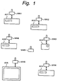
- Fig. 1 shows an outline of such a wireless network system.
- WN1, WN2, WN3, ... are wireless nodes as communicating stations.
- Digital audio units or digital video units AV1, AV2, .., such as a CD player, an MD recorder/player, a digital VCR, a digital camera, a DVD player, and a television receiver can be connected to the wireless nodes WN1, WN2, ...
- a personal computer can be connected to the wireless nodes WN1, WN2, WN3, ....
- Each of the digital audio units and digital video units AV1, AV2, ... connected to the wireless nodes WN1, WN2, ... has the IEEE 1394 digital interface.
- the wireless nodes WN1, WN2, ... and the digital audio units and digital video units AV1, AV2, ... are connected with the IEEE 1394 digital interface.
- the WNB is a wireless node as a controlling station.
- the wireless node WNB as the controlling station exchanges control data with the wireless nodes WN1, WN2, ... as the communicating stations.
- the wireless nodes WN1, WN2, ... as the communicating stations communicate each other under the control of the wireless node WNB as the controlling station.
- the wireless nodes WN1, WN2, ... as the communicating stations wirelessly exchange chronologically continuous data streams (isochronous data) and asynchronous data such as commands.
- a star type topology wireless LAN is structured.
- the wireless LAN is composed of a central controlling station CN and peripheral terminal stations TN1, TN2, ...
- the terminal stations TN1, TN2, ... exchange data under the control of the central controlling station CN.
- the central controlling station CN corresponds to the wireless node WNB.
- the terminal stations TN1, TN2, ... correspond to the wireless nodes WN1, WN2, ... It should be noted that the structure of the wireless LAN is not limited to such a star type topology.
- Control data chronologically continuous data streams such as audio data and video data
- asynchronous data such as commands are transmitted between the wireless nodes WN1, WN2, ... and the wireless node WNB.
- These types of data are transmitted as frames as shown in Fig. 3.
- FIG. 3 shows a frame structure of data transmitted between the wireless node WN1, WN2, ... and the volunteers node WNB.
- a control area MA for management information such as network information is placed at the beginning of one frame.
- the control area MA is followed by a stream packet transmission area SPA and an asynchronous transmission area ASYNCA.
- the stream packet transmission area SPA and the asynchronous transmission area ASYNCA compose a data transmission area.
- the stream packet transmission area SPA is used for a high speed communication equivalent to the isochronous transmission mode of the IEEE 1394 interface.
- the stream packet transmission area SPA is composed of time slots SL1, SL2, ...
- the time slots SL1, SL2, .. are units of which data is time-division multiplexed.
- the time slots are placed at intervals of a predetermined time period. In this example, the number of the time slots SL1, SL2, ... is 16. With different time slots SL1, SL2, ..., for example 16 data streams can be transmitted in the same system at a time.
- the number of time slots is 16.
- the number of time slots is not limited to 16.
- the time slots may be placed at any positions of a frame.
- the number of time slots SL1, SL2, ... used for one data stream is not constant.
- the bit rate of an MPEG (Moving Picture Experts Group) 2 data stream varies corresponding to its pattern or its motion.
- the number of time slots SL1, SL2, ... used for one data stream becomes large.
- the number of time slots SL1, SL2, ... used for one data stream becomes small.
- the asynchronous transmission area ASYNCA is equivalent to the asynchronous transmission mode of the IEEE 1394 interface.
- the asynchronous transmission area ASYNCA is used for asynchronous data such as commands.
- an acknowledgment signal sent back from the remote party is checked.
- a data re-transmitting operation is performed.
- the wireless node WNB as the central controlling station polls the wireless nodes WN1, WN2, ... as the communicating stations or detects carrier signals therefrom so as to prevent transmission requests from colliding on a transmission path.
- the time slots SL1, SL2, ... are allocated by the wireless node WNB as the controlling station.
- the wireless node WNB as the controlling station manages a communication state of the system and recognizes time slots that are being used.
- the wireless node WNB as the controlling station transmits management area information. With the management area information, each of the wireless node WN1, WN2, ... can determine what time slots SL1, SL2, ... are being used for what data streams.
- the wireless node WNB as the controlling station polls the wireless nodes WN1, WN2, ... as the communicating stations. When the wireless node WN1, WN2, ... have issued data stream transmission requests through the polling operation, they are transmitted to the wireless node WNB as the controlling station.
- the wireless node WNB as the controlling station allocates the time slots SL1, SL2, ... to the wireless nodes WN1, WN2, ... that have issued the data transmission requests.
- the wireless node WNB as the controlling station transmits information of the newly allocated time slots SL1, SL2, ... to the other wireless nodes WN1, WN2, ...
- the wireless nodes WN1, WN2, ... that have been requested for the data transmission transmit data streams to the remote stations with the allocated time slots SL1, SL2, ...
- the control area MA at the beginning of each frame has a communicating station state signal STATUS, a start command signal WAKE-UP, and a communicating station state change request signal STATUS_REQ.
- the communicating station state signal STATUS, the start command signal WAKE-UP, and the communicating station state change request signal STATUS_REQ are used to control sleep state and high priority state of the wireless nodes WN1, WN2, ... of the system.
- the communicating station state signal STATUS represents the state of the local communicating station.
- the wireless node WNB as the controlling station periodically transmits the communicating station state signal STATUS.
- the communicating station state signal STATUS represents for example three states of sleep state, normal state, and high priority state. When the value of the communicating station state signal STATUS is "00", it represents the sleep state. When the value of the communicating station state signal STATUS is "01”, it represents the normal state. When the value of the communicating station state signal STATUS is "10", it represents the high priority state.
- the sleep state represents that the local wireless node is not communicating.
- each of the wireless nodes WN1, WN2, ... is in sleep mode.
- the power consumption is very small.
- each wireless node can receive at least the start command signal WAKE-UP so as to restore the normal state.
- the wireless nodes WN1, WN2, ... are in the sleep state, since they are not communicating, the wireless node WNB as the controlling station does not poll them.
- the normal state represents that the local wireless node is normally operating.
- the wireless nodes WN1, WN2, ... are in the normal state, the controlling station WNB usually polls them.
- the high priority state represents that the wireless node WNB as the controlling station exchanges parameters with the wireless nodes WN1, WN2, ... in initializing mode.
- the wireless node WNB as the controlling station more frequently polls the wireless nodes WN1, WN2, ... than those in the normal state.
- the start command signal WAKE_UP causes the communicating stations WN1, WN2, ... to cancel the sleep state.
- the wireless nodes WN1, WN2, ... that are in the sleep state receive the start command signal WAKE_UP, they cancel the sleep state and enter the normal state.
- the communicating station state change request signal STATUS_REQ is transmitted so as to change the current state.
- the communicating station state change request signal is transmitted from the wireless nodes WN1, WN2, ...as the communicating stations.
- the wireless nodes WN1, WN2, ... as the communicating stations that are in the normal state enter the sleep state they transmit the communicating station state change request signal STATUS_REQ to the wireless node WNB as the controlling station so as to enter the sleep state.
- the wireless node WNB as the controlling station polls the wireless nodes WN1, WN2, ... as the communicating stations.
- the wireless node WNB as the controlling station has a polling list.
- the wireless node WNB as the controlling station polls the wireless nodes WN1, WN2, ... corresponding to the polling list.
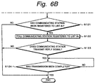
- Figs. 6A and 6B are flow charts showing a polling process performed by the controlling station.
- the wireless node WNB determines whether or not a wireless node has been registered to list number #1 (at step S101). When the determined result at step S101 is Yes, the wireless node WNB polls the wireless node registered to the list number #1 (at step S102). Thereafter, the wireless node WNB determines whether the wireless node registered to the list number #1 transmits a reply signal to the wireless node WNB (at step S103). When the determined result at step S103 is Yes, the wireless node WNB determines whether or not the transmission of the reply signal has been completed (at step S104). When the determined result at step S104 is Yes, the wireless node WNB performs the polling process for the next node. When the determined result at step S101 is No, the wireless node WNB performs the polling process for the next node.
- the wireless node WNB determined whether or not a wireless node has been registered to list number #2 (at step S111).
- the wireless node WNB polls the wireless node registered to the list number #2 (at step S112).
- the wireless node WNB determines whether or not the wireless node registered to the list number #2 transmits a reply signal (at step S113).
- the wireless node WNB determines whether or not the transmission of the reply signal has been completed (at step S114). Thereafter, the wireless node performs the polling process for the next wireless node.
- the wireless node WNB performs the polling process for the next node.
- the wireless node WNB repeats the similar process. In other words, the wireless node WNB determines whether or not a wireless node has been registered the last list number #n (at step S121). When the determined result at step S121 is Yes, the wireless node WNB polls the wireless node registered to the list number #n (at step S122). Thereafter, the wireless node WNB determines whether or not the wireless node registered to the list number #n transmits a reply signal (at step S123). When the determined result at step S123 is Yes, the wireless node WNB determines whether or not the transmission of the reply signal has been completed (at step S124). When the determined result at step S124 is Yes, the wireless node WNB completes the polling process. When the determined result at step S121 is No, the wireless node WNB completes the polling process.
- the wireless node WNB polls the wireless node WN1 registered to the list number #1 and the wireless node WN2 registered to the list number #2. Thereafter, corresponding to the polling list, the wireless node WNB polls the wireless nodes WN3, WN4, ...
- each wireless node can be set to one of the normal state, the sleep state, and the high priority state.
- the wireless node WNB successively polls the wireless nodes WN1, WN2, ...
- the wireless node WNB does not poll them.
- the wireless nodes WN1, WN2,... are set to the high priority state, the wireless node WNB more frequently polls the wireless nodes WN1, WN2, ... than those in the normal state.
- the states of the wireless nodes WN1, WN2, ... are controlled by changing the contents of the polling list.
- Fig. 7 shows the polling list in the case that the wireless node WN3 is set to the sleep state.
- the wireless nodes WN1 and WN2 have been registered to the list numbers #1 and #2, respectively, the wireless node WN3 has not been registered to the list number #3.
- the wireless node WNB polls the wireless nodes WN1, WN2, and WN4, rather than the wireless node WN3.
- the wireless node WNB does not poll the wireless node WN3.
- Fig. 8 shows the polling list in the case that the wireless node WN1 is set to the high priority state.
- the wireless node WN1 has been registered to the list number #1.
- the wireless node WN2 has been registered to the list number #2.
- the wireless node WN1 has been registered to the list number #3.
- the wireless node WN3 has been registered to the list number #4.
- the wireless node WN1 has been registered to the list number #5.
- the wireless node WNB successively polls the wireless nodes WN1, WN2, WN1, WN3, WN1, ...
- the wireless node WNB polls the wireless node WN1 every another wireless node.
- the wireless node WNB frequently polls the polling node that has been set to the high priority state.
- a wireless node that has been set to the high priority state is polled every another wireless node.
- the present invention is not limited to such a polling operation. Instead, a wireless node that has been set to the high priority state may be polled every two other wireless nodes or every three other wireless nodes. Alternatively, a wireless node that has been set to the high priority state may be successively polled a plurality of times.
- the control area MA at the beginning of each frame has the communicating station state signal STATUS, the start command signal WAKE-UP, and the communicating station state change request signal STATUS_REQ.
- the communicating station state signal STATUS, the start command signal WAKE-UP, and the communicating station state change request signal STATUS_REQ are used to control the sleep state.
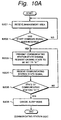
- FIGs. 9A and 9B are flow charts showing a process for causing the wireless node WN1, WN2, ... side to enter the sleep state corresponding to a request received from the wireless node WN1, WN2, ... side as a communicating station.
- Fig. 9A shows a process performed on the wireless node WN1, WN2, ... side as a communicating station.
- Fig. 9B shows a process performed on the wireless node WNB side as a controlling station.
- the wireless node side as the controlling station sets the communicating station state signal STATUS to "00" so as to enter the wireless node as the communicating station into the sleep state (at step S123).
- the wireless node side as the controlling station deletes the wireless node as the communicating station from the polling list (at step S124). Thereafter, the flow returns to step S121.
- the determined result at step S122 is Yes, since it is not necessary to change the state, the flow returns to step S121.
- the wireless node side as the communicating station After the wireless node side as the communicating station has transmitted the communicating station state change request signal STATUS_REQ, the wireless node side as the communicating station receives the communicating station state signal STATUS (at step S102).
- step S101 After the wireless node side as the communicating station has transmitted the communicating state change request signal STATUS_REQ at step S101 and the communicating state change request signal STATUS_REQ has been set to the sleep state at step S123, the flow advances to step S102.
- step S102 the wireless node side as the communicating station receives the communicating station state signal STATUS that has been set to the sleep state.
- the wireless node as the communicating station sets the mode to the sleep mode by itself (at step S104) and completes the process.
- the flow returns to step S101.
- the wireless node as the communicating station repeats the process.
- the wireless node WN1, WN2, ... side transmits the communicating station state change request signal STATUS_REQ to the wireless node WNB as the controlling station.
- the wireless node WNB as the controlling station sets the communicating station state signal STATUS to the sleep state so as to stop the polling operation for the communicating station in the sleep state.
- the wireless node WN1, WN2, ... side receives the communicating station state signal STATUS that has been set to the sleep state, the wireless node WN1, WN2, ... side enters the sleep mode.
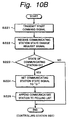
- FIGs. 10A and 10B show a process of which a wireless node WNB as a controlling station causes a wireless node that is in the sleep state to enter the normal state.
- Fig. 10A shows a process performed on the wireless node WN1, WN2, ... side as a communicating station.
- Fig. 10B shows a process performed on the wireless node WNB side as a controlling station.
- the wireless node when a wireless node as a communicating station is in the sleep state, the wireless node has been set to the sleep mode. In the sleep mode, the wireless node can receive at least the start command signal WAKE_UP of the control area MA at the beginning of each frame.
- the wireless node side as the communicating station in the sleep state receives the control area MA at the beginning of the frame (at step S201) and determines whether or not the start command signal WAKE_UP has been received (at step S202).
- the wireless node as the controlling station transmits the start command signal WAKE_UP to a wireless node so as to cancel the sleep state (at step S222).
- the wireless node When the wireless node as the communicating station in the sleep state has received the start command signal WAKE_UP at step S202, the wireless node transmits the communicating station state change request signal STATUS_REQ to the wireless node as the controlling station (at step S203).
- the controlling station receives the communicating station state change request signal STATUS_REQ (at step S222).
- the controlling station determines whether or not the current state of the communicating station is the normal state (at step S223). When the determined result at step S223 is No, the controlling station sets the communicating station state STATUS to the normal state (at step S224). The controlling station appends the wireless node as the communicating station to the polling list (at step S225) and completes the process. When the determined result at step S223 is Yes, since it is not necessary to change the state, the controlling station completes the process.
- the wireless node side After the wireless node side as the communicating station in the sleep state has transmitted the communicating station state change request signal STATUS_REQ at step S203, the wireless node side receives the communicating station state signal STATUS (at step S204).
- the wireless node side as the communicating station has transmitted the communicating station state change request signal STATUS_REQ to the wireless node as the controlling station at step S203.
- the wireless node as the controlling station has set the communicating station state STATUS to the normal state at step S224.
- the wireless node as the communicating station cancels the sleep state (at step S206) and completes the process.
- the flow returns to step S203.
- the wireless node as the communicating station repeats the process.
- the wireless node WNB as the controlling station transmits the start command signal WAKE_UP to the wireless node WN1, WN2, ... in the sleep state.
- Figs. 11A and 11B show a process of which the wireless node WN1, WN2, ... side as a communicating station in the sleep state enters the normal state by itself.
- Fig. 11A shows a process performed on the wireless node WN1, WN2, ... side as the communicating station.
- Fig. 11B shows a process performed on the wireless node WNB side as a controlling station.
- the wireless node side as the controlling station receives the communicating station state change request signal STATUS_REQ from the communicating station (at step S321).
- the controlling station appends the wireless node as the communicating station to the polling list (at step S324) and completes the process.
- the determined result at step S222 is Yes, since it is not necessary to change the state, the controlling station completes the process.
- the wireless node side After the wireless node side as the communicating station in the sleep state has transmitted the communicating station state change request signal STATUS_REQ that causes the wireless node side to enter the normal state, the wireless node side receives the communicating station state signal STATUS (at step S302).
- the wireless node side as the communicating station has transmitted the communicating station state change request signal STATUS_REQ to the controlling station at step S301.
- the wireless node as the controlling station has set the communicating station state signal STATUS to the normal state at step S323.
- the wireless node as the communicating station cancels the sleep state (at step S304) and completes the process.
- the determined result at step S303 is No, the flow returns to step S301.
- the wireless node as the communicating station repeats the process.
- the wireless node WN1, WN2, ... side in the sleep state When the wireless node WN1, WN2, ... side in the sleep state enters the normal state by itself, it transmits the communicating station state change request signal STATUS_REQ that causes it to enter the normal state. Thus, the wireless node WN1, WN2, ... side in the sleep state is entered into the normal state.
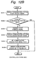
- Figs. 12A, 12B, and 12C show a process of which the wireless node WN1, WN2, ... as a communicating station (A) causes the wireless node WN1, WN2, ... as a communicating station (B) to enter into the sleep state.
- Fig. 12A shows a process performed on the wireless node WN1, WN2, ... side as the communicating station (A) that communicates with the communicating station (B) in the sleep state.
- Fig. 12B shows a process performed on the wireless node WNB side as the controlling station.
- Fig. 12C shows a process performed on the wireless node WN1, WN2, ... side as the communicating station (B) in the sleep state.
- the wireless node as the communicating station (A) transmits the communicating station start request signal that causes the wireless node as the communicating station (B) to enter the normal state (at step S401).
- the communicating station start request signal may be transmitted with control area MA or data area.
- step S422 When the determined result at step S422 is Yes, since the communicating station (B) is in the normal state, the controlling station completes the process.
- the wireless node as the controlling station transmits the start command signal WAKE_UP to the wireless node as the communicating station (B) (at step S423).
- the wireless node as the communicating station (B) in the sleep state receives the control area MA (at step S431) and determines whether or not the start command signal WAKE_UP has been received (at step S432).
- the communicating station (B) transmits the communicating station state change request signal STATUS_REQ that causes the state to be set to the normal state to the wireless node as the controlling station (at step S433).
- the wireless node as the controlling station receives the communicating station state change request signal STATUS_REQ from the communicating station (B) (at step S424) and sets the communicating station state signal STATUS to the normal state (at step S425).
- the wireless node as the controlling station appends the wireless node as the communicating station (B) to the polling list (at step S426) and completes the process.
- the wireless node as the communicating station (B) cancels the sleep mode and completes the process.
- the determined result at step S435 No, the flow returns to step S433.
- the wireless node as the communicating station (B) repeats the process.
- the wireless node side as the communicating station (A) receives the communicating station state signal STATUS from the communicating station (B) (at step S402).
- the determined result at step S403 is Yes, since the sleep mode of the communicating station (B) has been canceled, the communicating station (A) completes the process.
- the determined result at step S403 is No, the flow returns to step S401.
- the wireless node as the communicating station (A) repeats the process.
- the control area MA at the beginning of each frame has the communicating station state signal STATUS, the start command signal WAKE_UP, and the communicating station state change request signal STATUS_REQ.
- the communicating station state signal STATUS, the start command signal WAKE_UP, and the communicating station state change request signal STATUS_REQ With the communicating station state signal STATUS, the start command signal WAKE_UP, and the communicating station state change request signal STATUS_REQ, the wireless nodes WN1, WN2, ... in the system can be set to the sleep state.
- Fig. 13 shows the structure of each of the wireless nodes WN1, WN2, ..., and WNB.
- the structure of the wireless node WNB as the controlling station is basically the same as the structure of each of the wireless nodes WN1, WN2, ... as the communicating stations.
- each of the wireless nodes WN1, WN2, ... and WNB has an IEEE 1394 digital interface 11.
- the IEEE 1394 digital interface 11 supports chronologically continuous data (isochronous data) such as digital audio data and digital video data and asynchronous data such as commands.
- each of the wireless nodes WN1, WN2, ... WNB has an encoding/decoding portion 12, a radio frequency transmission processing portion 13, a transmission control managing portion 14, and a connection information storing portion 15.
- the encoding/decoding portion 12 encodes transmission data and decodes reception data. When a data stream is transmitted, the encoding/decoding portion 12 performs an error correction code encoding process for the data stream with a block code. In addition, the encoding/decoding portion 12 performs the error correcting process for reception data.
- the radio frequency transmission processing portion 13 modulates the transmission signal, converts the resultant signal into a signal of a predetermined frequency, amplifies the resultant signal in a desired power level, extracts a signal of a predetermined frequency from the reception signal, converts the resultant signal into a signal of an intermediate frequency, and demodulates the resultant signal.
- modulating methods include QPSK and multi-value QAM modulating method.
- the resultant data may be secondarily modulated by spectrum dispersing method or OFDM (Orthogonal Frequency Division Multiplexing) method.
- the transmission control managing portion 14 manages the data transmission. In other words, as described above, in this system, data is transmitted as frames. Data streams such as digital video data are transmitted with time slots. When asynchronous data is transmitted, the transmission control managing portion 14 determines whether data has been transmitted corresponding to an acknowledgment signal. When data has not been transmitted, the transmission control managing portion 14 performs a re-transmitting operation.
- the connection information storing portion 15 stores network connection information that represents what transmission uses what time slots.
- the connection information is transmitted and received as management area information.
- the connection information storing portion 15 stores the polling list 20.
- the polling list 20 is used when the wireless node WNB as the controlling station polls the wireless nodes WN1, WN2, ... as the communicating stations.
- Each of the wireless nodes WN1, WN2, ... and WNB has a sleep mode setting portion 21.
- the sleep mode setting portion 21 sets the node to the sleep mode.
- the sleep mode setting portion 21 determines whether or not the current node has operated for a predetermined time period.
- the sleep mode setting portion 21 sets the current node to the sleep mode.
- the sleep mode the power to circuits other than required circuits is stopped.
- the clock frequency is decreased.
- the sleep mode at a timing of the start command signal WAKE_UP in the control area MA at the beginning of each frame, a signal is received.
- control information is output from the transmission control managing portion 14 to the encoding/decoding portion 12.
- an output signal of the encoding/decoding portion 12 is supplied to the radio frequency transmission processing portion 13.
- the radio frequency transmission processing portion 13 modulates the signal in a predetermined modulating method, converts the resultant signal into a signal of a predetermined frequency, and amplifies the resultant signal in a desired power level.
- An output signal of the radio frequency transmission processing portion 13 is transmitted from the antenna 16.
- the data stream When a data stream is transmitted, the data stream is supplied to the encoding/decoding portion 12 through the digital interface 11.
- the encoding/decoding portion 12 adds an error correction code as a block code to the data stream.
- the data stream Under the control of the transmission control managing portion 14, the data stream is allocated to predetermined time slots. In the time period of the allocated time slot, an output signal of the encoding/decoding portion 12 is supplied to the radio frequency transmission processing portion 13.
- the radio frequency transmission processing portion 13 modulates the signal in a predetermined modulating method, converts the signal into a signal of a predetermined transmission frequency, amplifies the resultant signal in a desired power level, and transmits the resultant signal from the antenna 16.
- the asynchronous data When asynchronous data is transmitted, the asynchronous data is supplied to the encoding/decoding portion 12 through the digital interface 11.
- the encoding/decoding portion 12 arranges the asynchronous data into a predetermined data sequence. Since a re-transmitting operation is performed for the asynchronous data, an error correction code encoding process is not performed for the asynchronous data.
- the transmission timing of the data Under the control of the transmission control managing portion 14, the transmission timing of the data is designated.
- an output signal of the encoding/decoding portion 12 is supplied to the radio frequency transmission processing portion 13.
- the radio frequency transmission processing portion 13 modulates the signal in a predetermined modulating method, converts the resultant signal into a signal of a predetermined transmission frequency, amplifies the resultant signal in a desired power level, and transmits the resultant signal from the antenna 16.
- a signal that is received from the antenna 16 is supplied to the radio frequency transmission processing portion 13.
- the radio frequency processing portion 13 converts the reception signal into a signal of an intermediate frequency, and demodulates the resultant signal into a base band signal.
- an output signal of the radio frequency transmission processing portion 13 is supplied to the encoding/decoding portion 12.
- the encoding/decoding portion 12 decodes the information in the control area MA.
- the information in the control area MA is supplied to the transmission control managing portion 14.
- an output signal of the radio frequency transmission processing portion 13 is supplied to the encoding/decoding portion 12.
- the encoding/decoding portion 12 performs an error correcting process for the data stream transmitted with the predetermined time slots.
- An output signal of the encoding/decoding portion 12 is supplied to a predetermined unit through the digital interface 11.
- the communicating station state signal STATUS, the start command signal WAKE_UP, and the communication state change signal STATUS_REQ are placed in the control area MA at the beginning of each frame.
- the communication state change signal STATUS_REQ With the communication state change signal STATUS_REQ, the sleep operation can be controlled.
- the length of one frame and the lengths of the stream transmission area and asynchronous transmission area are designated corresponding to transmission conditions.
- the asynchronous transmission area is preceded by the stream transmission area.
- the present invention is not limited to such an arrangement. Instead, the stream transmission area may be preceded by the asynchronous transmission area.
- a communicating station transmits a communicating station state change request signal to a controlling station.
- the controlling station transmits a communicating station state signal to the communicating station so as to enter the communicating station into a sleep state.
- the local station can enter into the sleep state by itself.
- the local station can be entered into the sleep state corresponding a command received from the controlling station.
- a communicating station in the sleep state always receives at least a start command signal.
- the communicating station in the sleep state can cancel the sleep state by itself.
- the sleep state of the communicating station can be canceled corresponding to a command received from the controlling station.
Landscapes
- Engineering & Computer Science (AREA)
- Computer Networks & Wireless Communication (AREA)
- Signal Processing (AREA)
- Multimedia (AREA)
- Mobile Radio Communication Systems (AREA)
- Small-Scale Networks (AREA)
- Power Sources (AREA)
Applications Claiming Priority (2)
| Application Number | Priority Date | Filing Date | Title |
|---|---|---|---|
| JP06679098 | 1998-03-17 | ||
| JP06679098A JP3463555B2 (ja) | 1998-03-17 | 1998-03-17 | 無線通信方法、無線通信システム、通信局、及び制御局 |
Publications (3)
| Publication Number | Publication Date |
|---|---|
| EP0952701A2 true EP0952701A2 (de) | 1999-10-27 |
| EP0952701A3 EP0952701A3 (de) | 2003-04-02 |
| EP0952701B1 EP0952701B1 (de) | 2005-08-03 |
Family
ID=13326020
Family Applications (1)
| Application Number | Title | Priority Date | Filing Date |
|---|---|---|---|
| EP99302024A Expired - Lifetime EP0952701B1 (de) | 1998-03-17 | 1999-03-16 | Drahtloses Kommunikationsverfahren und -System, Übertragungsstation, und Steuerstation |
Country Status (4)
| Country | Link |
|---|---|
| US (1) | US6545999B1 (de) |
| EP (1) | EP0952701B1 (de) |
| JP (1) | JP3463555B2 (de) |
| DE (1) | DE69926431T2 (de) |
Cited By (2)
| Publication number | Priority date | Publication date | Assignee | Title |
|---|---|---|---|---|
| WO2010042789A1 (en) * | 2008-10-09 | 2010-04-15 | Qualcomm Incorporated | Method and apparatus for power saving in a wireless communication system |
| EP1758302A4 (de) * | 2004-05-28 | 2010-07-28 | Nokia Corp | Netzwerksystem |
Families Citing this family (43)
| Publication number | Priority date | Publication date | Assignee | Title |
|---|---|---|---|---|
| JP3651340B2 (ja) * | 1999-12-28 | 2005-05-25 | ソニー株式会社 | 無線伝送方法および無線伝送装置 |
| JP2001230795A (ja) * | 2000-02-16 | 2001-08-24 | Sony Corp | 無線伝送方法および無線伝送装置 |
| JP3623453B2 (ja) * | 2000-02-23 | 2005-02-23 | シャープ株式会社 | 非同期伝送方法 |
| US6647441B1 (en) * | 2000-09-15 | 2003-11-11 | Hewlett-Packard Development Company, L.P. | Method of maximizing servicing capability of large numbers of I/O descriptors |
| JP2002135314A (ja) * | 2000-10-26 | 2002-05-10 | Sharp Corp | 通信制御方法および通信機器 |
| US7089014B2 (en) * | 2001-08-06 | 2006-08-08 | Metric Systems Corporation | Wireless communication system control apparatus and method |
| US7218948B2 (en) | 2003-02-24 | 2007-05-15 | Qualcomm Incorporated | Method of transmitting pilot tones in a multi-sector cell, including null pilot tones, for generating channel quality indicators |
| US8811348B2 (en) * | 2003-02-24 | 2014-08-19 | Qualcomm Incorporated | Methods and apparatus for generating, communicating, and/or using information relating to self-noise |
| US9544860B2 (en) * | 2003-02-24 | 2017-01-10 | Qualcomm Incorporated | Pilot signals for use in multi-sector cells |
| US9661519B2 (en) * | 2003-02-24 | 2017-05-23 | Qualcomm Incorporated | Efficient reporting of information in a wireless communication system |
| WO2004088927A1 (ja) | 2003-03-27 | 2004-10-14 | Matsushita Electric Industrial Co., Ltd. | 間欠通信方法及び間欠通信装置 |
| JP4576102B2 (ja) * | 2003-08-06 | 2010-11-04 | ミツミ電機株式会社 | 通信システム及び通信装置並びに通信方法 |
| US7319867B2 (en) * | 2003-09-15 | 2008-01-15 | Atheros Communications, Inc. | Method and apparatus for wake on wireless systems |
| KR20060073419A (ko) | 2004-06-14 | 2006-06-28 | 삼성전자주식회사 | 분산화 개인용무선네트워크에서의 전력절감 기능을 구비한시스템 및 방법 |
| US20060092881A1 (en) * | 2004-10-14 | 2006-05-04 | Rajiv Laroia | Methods and apparatus for determining, communicating and using information which can be used for interference control purposes |
| US8503938B2 (en) | 2004-10-14 | 2013-08-06 | Qualcomm Incorporated | Methods and apparatus for determining, communicating and using information including loading factors which can be used for interference control purposes |
| NZ555079A (en) | 2004-10-14 | 2010-04-30 | Qualcomm Inc | Methods and apparatus for determining, communicating and using information which can be used for interference control purposes |
| JP4701824B2 (ja) | 2005-05-11 | 2011-06-15 | ソニー株式会社 | 無線通信装置およびその制御方法 |
| US7653041B2 (en) * | 2005-05-12 | 2010-01-26 | National Chiao Tung University | Method for power-efficient transmission supporting integrated services over wireless local area network |
| US8694042B2 (en) * | 2005-10-14 | 2014-04-08 | Qualcomm Incorporated | Method and apparatus for determining a base station's transmission power budget |
| US9191840B2 (en) * | 2005-10-14 | 2015-11-17 | Qualcomm Incorporated | Methods and apparatus for determining, communicating and using information which can be used for interference control |
| US9137072B2 (en) | 2005-12-22 | 2015-09-15 | Qualcomm Incorporated | Methods and apparatus for communicating control information |
| US8437251B2 (en) | 2005-12-22 | 2013-05-07 | Qualcomm Incorporated | Methods and apparatus for communicating transmission backlog information |
| US8514771B2 (en) * | 2005-12-22 | 2013-08-20 | Qualcomm Incorporated | Methods and apparatus for communicating and/or using transmission power information |
| US9148795B2 (en) * | 2005-12-22 | 2015-09-29 | Qualcomm Incorporated | Methods and apparatus for flexible reporting of control information |
| US9125092B2 (en) | 2005-12-22 | 2015-09-01 | Qualcomm Incorporated | Methods and apparatus for reporting and/or using control information |
| US9338767B2 (en) | 2005-12-22 | 2016-05-10 | Qualcomm Incorporated | Methods and apparatus of implementing and/or using a dedicated control channel |
| US9125093B2 (en) * | 2005-12-22 | 2015-09-01 | Qualcomm Incorporated | Methods and apparatus related to custom control channel reporting formats |
| US9473265B2 (en) * | 2005-12-22 | 2016-10-18 | Qualcomm Incorporated | Methods and apparatus for communicating information utilizing a plurality of dictionaries |
| US9572179B2 (en) * | 2005-12-22 | 2017-02-14 | Qualcomm Incorporated | Methods and apparatus for communicating transmission backlog information |
| US20070149132A1 (en) | 2005-12-22 | 2007-06-28 | Junyl Li | Methods and apparatus related to selecting control channel reporting formats |
| US20070249360A1 (en) * | 2005-12-22 | 2007-10-25 | Arnab Das | Methods and aparatus related to determining, communicating, and/or using delay information in a wireless communications system |
| US9451491B2 (en) * | 2005-12-22 | 2016-09-20 | Qualcomm Incorporated | Methods and apparatus relating to generating and transmitting initial and additional control information report sets in a wireless system |
| US9119220B2 (en) | 2005-12-22 | 2015-08-25 | Qualcomm Incorporated | Methods and apparatus for communicating backlog related information |
| US20070243882A1 (en) * | 2006-04-12 | 2007-10-18 | Qualcomm Incorporated | Method and apparatus for locating a wireless local area network associated with a wireless wide area network |
| EP2119303A2 (de) * | 2007-03-13 | 2009-11-18 | Syngeta Participations AG | Verfahren und systeme für ein adhoc-sensornetzwerk |
| JP2009060621A (ja) * | 2008-09-10 | 2009-03-19 | Victor Co Of Japan Ltd | 無線パケットデータ伝送システム |
| KR101601775B1 (ko) * | 2009-11-11 | 2016-03-21 | 삼성전자주식회사 | 무선통신시스템에서 신호를 전송하기 위한 장치 및 방법 |
| US9285856B2 (en) * | 2010-12-21 | 2016-03-15 | Qualcomm Incorporated | Method and system for rapid entry into and for rapid exiting from sleep states for processors of a portable computing device |
| US9104499B2 (en) | 2010-12-21 | 2015-08-11 | Qualcomm Incorporated | System for minimizing resource latency between processor application states in a portable computing device by scheduling resource state set transitions |
| US8954980B2 (en) | 2011-11-11 | 2015-02-10 | Qualcomm Incorporated | Conserving power through work load estimation for a portable computing device using scheduled resource set transitions |
| JP2018046517A (ja) * | 2016-09-16 | 2018-03-22 | インターブリッジ合同会社 | 自律型小型無線装置及びその分散設置方法 |
| JP7093485B2 (ja) * | 2018-01-24 | 2022-06-30 | インターブリッジ合同会社 | 自律型小型無線装置及びその分散設置方法 |
Family Cites Families (12)
| Publication number | Priority date | Publication date | Assignee | Title |
|---|---|---|---|---|
| US5241542A (en) * | 1991-08-23 | 1993-08-31 | International Business Machines Corporation | Battery efficient operation of scheduled access protocol |
| US5440560A (en) * | 1991-12-24 | 1995-08-08 | Rypinski; Chandos A. | Sleep mode and contention resolution within a common channel medium access method |
| JP2796464B2 (ja) * | 1991-12-27 | 1998-09-10 | 株式会社日立製作所 | 無線通信システム、および、無線通信方法 |
| JPH06132968A (ja) | 1992-10-20 | 1994-05-13 | Sharp Corp | 電源制御機能を備える通信装置 |
| FI96656C (fi) * | 1992-11-27 | 1996-07-25 | Nokia Telecommunications Oy | Radiojärjestelmä |
| JP2752030B2 (ja) * | 1993-04-16 | 1998-05-18 | 沖電気工業株式会社 | ローカルエリアネットワーク回線における信号送受信装置 |
| JP3453405B2 (ja) * | 1993-07-19 | 2003-10-06 | マツダ株式会社 | 多重伝送装置 |
| US5590396A (en) * | 1994-04-20 | 1996-12-31 | Ericsson Inc. | Method and apparatus for a deep-sleep mode in a digital cellular communication system |
| US5535207A (en) * | 1994-05-20 | 1996-07-09 | Motorola, Inc. | Method of dynamically allocating time slots on a packet data communications channel |
| US6151352A (en) * | 1996-04-16 | 2000-11-21 | Brother Kogyo Kabushiki Kaisha | Wireless communication using a frequency hopping method |
| US6085114A (en) * | 1997-02-06 | 2000-07-04 | At&T Wireless Systems Inc. | Remote wireless unit having reduced power operating mode |
| WO1998035473A2 (en) * | 1997-02-06 | 1998-08-13 | At & T Wireless Services, Inc. | Remote wireless unit having reduced power operating mode |
-
1998
- 1998-03-17 JP JP06679098A patent/JP3463555B2/ja not_active Expired - Fee Related
-
1999
- 1999-03-15 US US09/267,339 patent/US6545999B1/en not_active Expired - Lifetime
- 1999-03-16 EP EP99302024A patent/EP0952701B1/de not_active Expired - Lifetime
- 1999-03-16 DE DE69926431T patent/DE69926431T2/de not_active Expired - Lifetime
Cited By (4)
| Publication number | Priority date | Publication date | Assignee | Title |
|---|---|---|---|---|
| EP1758302A4 (de) * | 2004-05-28 | 2010-07-28 | Nokia Corp | Netzwerksystem |
| WO2010042789A1 (en) * | 2008-10-09 | 2010-04-15 | Qualcomm Incorporated | Method and apparatus for power saving in a wireless communication system |
| US8874065B2 (en) | 2008-10-09 | 2014-10-28 | Qualcomm Incorporated | Method and apparatus for facilitating power conservation via time-gating in a wireless communication system |
| US9936449B2 (en) | 2008-10-09 | 2018-04-03 | Qualcomm Incorporated | Method and apparatus for facilitating power conservation via time-gating in a wireless communication system |
Also Published As
| Publication number | Publication date |
|---|---|
| DE69926431D1 (de) | 2005-09-08 |
| EP0952701A3 (de) | 2003-04-02 |
| DE69926431T2 (de) | 2006-03-30 |
| JP3463555B2 (ja) | 2003-11-05 |
| EP0952701B1 (de) | 2005-08-03 |
| US6545999B1 (en) | 2003-04-08 |
| JPH11266254A (ja) | 1999-09-28 |
Similar Documents
| Publication | Publication Date | Title |
|---|---|---|
| EP0952701B1 (de) | Drahtloses Kommunikationsverfahren und -System, Übertragungsstation, und Steuerstation | |
| US6542495B1 (en) | Wireless communicating method, wireless communicating system, communicating station, and controlling station | |
| US7251231B2 (en) | Method and apparatus for controlling communication within a computer network | |
| US7093015B2 (en) | Method and apparatus for accessing a wireless computer network communication channel by accessing quiet intervals in network frames | |
| US20030231621A1 (en) | Dynamic communication channel switching for computer networks | |
| US6754176B1 (en) | Scheme for managing overlapping wireless computer networks | |
| US6069887A (en) | Method and system for synchronization in a wireless local area network | |
| US6816477B1 (en) | Transmission method in a domestic communication system comprising a wireless channel | |
| US5297144A (en) | Reservation-based polling protocol for a wireless data communications network | |
| US6466587B1 (en) | Wireless transmitting method | |
| EP1475924B1 (de) | Drahtlose ad hoc Kommunikation mit unterschiedlicher Sendeleistung für Kopf und Nutzlast der Nachrichten | |
| US7953030B2 (en) | Method and apparatus for controlling power consumption of stations on a CSMA/CA-based wireless LAN | |
| CN104412518A (zh) | 用于无线网络中上行链路传输的系统和方法 | |
| US8179914B1 (en) | Network slot synchronization scheme for a computer network communication channel | |
| EP0939510A2 (de) | Verfahren zur drahtlosen Übertragung | |
| EP1195025A1 (de) | Netzwerkzeitschlitzsynchronisationsschema für einen kommunikationskanal in einem rechnernetzwerk | |
| WO2004100461A1 (en) | Wireless ad hoc communication with different power levels for message header and payload | |
| EP1112643A1 (de) | Schutzverfahren für ein steuerbares nicht einrastendes halbleiter-schaltelement und hierzu korrespondierende schutzschaltung |
Legal Events
| Date | Code | Title | Description |
|---|---|---|---|
| PUAI | Public reference made under article 153(3) epc to a published international application that has entered the european phase |
Free format text: ORIGINAL CODE: 0009012 |
|
| AK | Designated contracting states |
Kind code of ref document: A2 Designated state(s): AT BE CH CY DE DK ES FI FR GB GR IE IT LI LU MC NL PT SE |
|
| AX | Request for extension of the european patent |
Free format text: AL;LT;LV;MK;RO;SI |
|
| PUAL | Search report despatched |
Free format text: ORIGINAL CODE: 0009013 |
|
| AK | Designated contracting states |
Kind code of ref document: A3 Designated state(s): AT BE CH CY DE DK ES FI FR GB GR IE IT LI LU MC NL PT SE Designated state(s): AT BE CH CY DE DK ES FI FR GB GR IE IT LI LU MC NL PT SE |
|
| AX | Request for extension of the european patent |
Extension state: AL LT LV MK RO SI |
|
| 17P | Request for examination filed |
Effective date: 20030911 |
|
| 17Q | First examination report despatched |
Effective date: 20031008 |
|
| AKX | Designation fees paid |
Designated state(s): DE FR GB |
|
| GRAP | Despatch of communication of intention to grant a patent |
Free format text: ORIGINAL CODE: EPIDOSNIGR1 |
|
| GRAS | Grant fee paid |
Free format text: ORIGINAL CODE: EPIDOSNIGR3 |
|
| GRAA | (expected) grant |
Free format text: ORIGINAL CODE: 0009210 |
|
| AK | Designated contracting states |
Kind code of ref document: B1 Designated state(s): DE FR GB |
|
| REG | Reference to a national code |
Ref country code: GB Ref legal event code: FG4D |
|
| REF | Corresponds to: |
Ref document number: 69926431 Country of ref document: DE Date of ref document: 20050908 Kind code of ref document: P |
|
| ET | Fr: translation filed | ||
| PLBE | No opposition filed within time limit |
Free format text: ORIGINAL CODE: 0009261 |
|
| STAA | Information on the status of an ep patent application or granted ep patent |
Free format text: STATUS: NO OPPOSITION FILED WITHIN TIME LIMIT |
|
| 26N | No opposition filed |
Effective date: 20060504 |
|
| PGFP | Annual fee paid to national office [announced via postgrant information from national office to epo] |
Ref country code: FR Payment date: 20120403 Year of fee payment: 14 |
|
| PGFP | Annual fee paid to national office [announced via postgrant information from national office to epo] |
Ref country code: DE Payment date: 20120323 Year of fee payment: 14 |
|
| PGFP | Annual fee paid to national office [announced via postgrant information from national office to epo] |
Ref country code: GB Payment date: 20120322 Year of fee payment: 14 |
|
| REG | Reference to a national code |
Ref country code: GB Ref legal event code: 746 Effective date: 20120702 |
|
| REG | Reference to a national code |
Ref country code: DE Ref legal event code: R084 Ref document number: 69926431 Country of ref document: DE Effective date: 20120614 |
|
| GBPC | Gb: european patent ceased through non-payment of renewal fee |
Effective date: 20130316 |
|
| REG | Reference to a national code |
Ref country code: FR Ref legal event code: ST Effective date: 20131129 |
|
| REG | Reference to a national code |
Ref country code: DE Ref legal event code: R119 Ref document number: 69926431 Country of ref document: DE Effective date: 20131001 |
|
| PG25 | Lapsed in a contracting state [announced via postgrant information from national office to epo] |
Ref country code: FR Free format text: LAPSE BECAUSE OF NON-PAYMENT OF DUE FEES Effective date: 20130402 Ref country code: DE Free format text: LAPSE BECAUSE OF NON-PAYMENT OF DUE FEES Effective date: 20131001 Ref country code: GB Free format text: LAPSE BECAUSE OF NON-PAYMENT OF DUE FEES Effective date: 20130316 |