EP0952097A1 - Device for changing the load-moving conditions on a roller conveyor - Google Patents
Device for changing the load-moving conditions on a roller conveyor Download PDFInfo
- Publication number
- EP0952097A1 EP0952097A1 EP99420100A EP99420100A EP0952097A1 EP 0952097 A1 EP0952097 A1 EP 0952097A1 EP 99420100 A EP99420100 A EP 99420100A EP 99420100 A EP99420100 A EP 99420100A EP 0952097 A1 EP0952097 A1 EP 0952097A1
- Authority
- EP
- European Patent Office
- Prior art keywords
- rollers
- roller
- conveyor
- chains
- load
- Prior art date
- Legal status (The legal status is an assumption and is not a legal conclusion. Google has not performed a legal analysis and makes no representation as to the accuracy of the status listed.)
- Granted
Links
Images
Classifications
-
- B—PERFORMING OPERATIONS; TRANSPORTING
- B65—CONVEYING; PACKING; STORING; HANDLING THIN OR FILAMENTARY MATERIAL
- B65G—TRANSPORT OR STORAGE DEVICES, e.g. CONVEYORS FOR LOADING OR TIPPING, SHOP CONVEYOR SYSTEMS OR PNEUMATIC TUBE CONVEYORS
- B65G13/00—Roller-ways
- B65G13/08—Roller-ways of curved form; with branch-offs
- B65G13/10—Switching arrangements
Definitions
- the invention relates to the field of roller conveyors composed of a frame carrying rollers which, parallel to each other and horizontal, are mounted to rotate freely in the chassis and are connected to means capable of driving them in rotation, at least in one direction, for longitudinally move the loads placed on them.
- the object of the present invention is to remedy these drawbacks by providing a space-saving device for modifying the conditions of displacement of the loads and, in particular, their direction of displacement without causing the interruption of the transfer of these charges.
- the device comprises at least two juxtaposed and motorized rollers on the periphery of each of which are wound and fixed several rings or turns of a roller chain whose axis of rotation of the rollers forms, with respect to the axis of rotation of the roller, a angle between 0 and 60 °, each of the rollers being free to rotate by relative to its links and at least locally beyond them to come in contact with the load in the support plane delimited by the other rollers of the conveyor.
- the means for retaining the loads are constituted by stops, fixed or eclipsable, or by another pair of roller chain rollers arranged downstream of the first, but of which the direction of winding of the chains is opposite to that of the chains of these first rollers, these second rollers being connected to means rotational drive separate from those of the first rollers and whose direction of rotation is reversible.
- the device comprises at least two rollers on each of which roller chains are wound with a zero turn angle and form rings, these rollers being connected to rotational drive means distinct from those for driving normal conveyor rollers suitable for driving chain rollers rollers at a speed different from that of normal rollers, to slow down or accelerate charges.
- the device comprises two rollers parallel on each of which two sections of roller chains are wound with the same winding angle, but with a direction of different winding, namely, for the upstream roller, from the outside to the middle of the roll, and for the downstream roll, from the middle to the outside, and both rollers are connected to separate rotational drive means including minus that of the downstream roller is reversibly so, when rotation in opposite direction to that of the upstream roller, to cause the rotation of the burden on itself.
- This arrangement allows the load to be rotated on the roller downstream, for example, to orient it before a sampling device, such as a manipulator, or in anticipation of its transfer to a transverse conveyor.
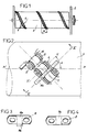
- the invention relates to roller conveyors C1, C2, Cn, composed of a frame 2 carrying rollers 3, parallel and horizontal, mounted free to rotate in this chassis and connected to means capable of driving them in rotation at the same speed or different speed.
- These means are, for example, constituted by pinions wedged on the shaft of each roller 3 and on which mesh chains or toothed belts 4.
- the device according to the invention which is included in a conveyor of the aforementioned type, comprises at least two rollers 5, of smaller diameter and each carrying a chain 6 with rollers 7, wound on its periphery.
- each chain is wound helically on a roller 5 extending from one of its ends to its other end.
- the helix angle a can vary from a few degrees to 60 °.
- This propeller can be wound to the right, that is to say going from left to right, or on the contrary to the left, that is to say going from right to left depending on the applications.
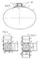
- each of the rollers 7 of the chain 6 is mounted to rotate freely on an axis 8 each of whose ends passes through one of the bearings of an internal link 9 and one of the bearings of a link external 10 on which it is riveted.
- the geometrical axis y'-y of each of the axes 8 is of course inclined at an angle a relative to the longitudinal axis x'-x of the roller 5, as shown in FIG. 2.
- each internal links 9 and external links 10 thereof are twisted, as shown in FIGS. 4 and 3 respectively.
- This twisting or warping angle is determined in relation to the angle of the winding propeller of the chain 6 on roller 5 and with the outside diameter of this roller.
- Figures 3 and 4 show that this twist only affects the ends of each of the links 9 and 10 which therefore keep a central part which is not twisted, respectively 9a, 10a.
- each of the outer links 10 is secured to a bent tab 10b which, when the link is assembled, protrudes outward and downward and allows to fix this link on the wall of the roller 5.
- this fixing is ensured by welding. It can be provided by bonding with a plastic roller.
- Figure 5 shows that the dimensions of the roller 5 and the rollers 7 are determined so that each roller 7 comes into contact with the load A, substantially in the horizontal contact plane PH of this load with normal rollers 3 of the conveyor.
- This figure also shows that, due to the warping given to the links, when a roller 7 is in position of contact with the load A, its axis of rotation y'-y is inclined by relative to the horizontal diametral plane H of the cylinder.
- this device comprises two rollers 5.
- These rollers are identical, say have 6 roller chains wound in the same direction and with the same winding angle. These chains are materialized by bars 6a representing their turns.
- Each of the rollers is connected to means rotational drive 4 which, in this embodiment, are common with those driving the normal rollers 3.
- the switching device consisting of the two rollers 5 is arranged at the end of the conveyor C1 and is associated with a fixed stop 13, arranged downstream of it and at the end of the conveyor C1.
- the device according to the invention is not disposed at the end of the conveyor C1 but in a section of it, so that this conveyor C1 extends beyond the referral device.
- This conveyor C1 is equipped with a stop 13a which, disposed downstream of the device, is retractable vertically.
- the stop 13a is in the lowered retracted position, that is to say below of the load movement plan on conveyor C1
- all load A circulating on this conveyor and arriving on the rollers 5 to chain rollers continues its rectilinear trajectory, represented by the arrow 14.
- the stop 13a By against, if the stop 13a is moved vertically to come into the trajectory of load A, this load is moved transversely on the conveyor C2, as shown by arrow 15.
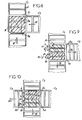
- the conveyor C1 is continuous and is associated with a transverse feed conveyor C3.
- the switching device comprises three rollers 5a including chains 6 with rollers 7 are wound with the same helix angle and with left hand propellers.
- the rollers 5a are driven in the same direction and at the same speed as the rollers 3 of conveyor C1.
- the device comprises a stop 13a, vertically retractable and arranged transversely to the trajectory of movement of the conveyor C1, downstream of the rollers 5a, and a fixed stop 16 arranged on the edge of the conveyor C1, which is opposite to the conveyor C3 and in the path of this conveyor C3.
- the lowering of the stop retractable 13a can be done automatically. It is the same for its elevation which can be triggered by passing the load over a contactor or a sensor arranged in the conveyor C3.
- the means of load retaining A constituted until now by stops are replaced by two other rollers 5b with roller chains arranged downstream, but next to the first rollers 5.
- the chains 6 to rollers 7 are wound in the opposite direction to those of rollers 5 and, by example, are wound with a helix on the left if the rollers 5 have a right propeller.
- these two rollers 5b are connected to means motors 20 which are separate from the means 4 ensuring the rotational drive rollers 5 and which, in addition, are reversible, that is to say can cause the rollers 5b in one direction or the other.
- Figure 10 shows the application of the device to a switch for cross crossing between a first conveyor C4 and a lateral conveyor C5 extended beyond the C4 conveyor by another C6 conveyor.
- the switching device is composed of two pairs of rollers rollers, namely two rollers 5c each carrying a chain 6 with rollers 7 helically wound with a left hand propeller and a pair of rollers 5d equipped with a roller chain helically wound on the right.
- the first pair of rollers 5c is rotated by the same means 4 as those driving the rollers 3 of the conveyor C4, while the rollers 5d are driven by separate and reversible means 20.
- the device according to the invention allows, for a small footprint, to make switches between conveyor for transferring, at a right angle or at any other angle, the loads from a conveyor.
- the device according to the invention makes it possible to brake or slow down a load.
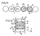
- Its 5th rollers are at less than two, and can therefore be more, and carry sections 6b of chains 6 which, wound on them with a zero helix angle, form spaced rings.
- the axis of the rollers 7 is therefore parallel to the axis of rotation of the 5th rollers.
- These rollers are rotated by motor means 24 which are independent for each roller and independent of the means 4 ensuring the rotation of normal rollers 3 of the conveyor.
- Each of these motor means 24 can drive one of the 5th rollers with a peripheral linear speed V2 which is different from the linear speed V1 rollers 3 and each of the following 5th rollers.
- rollers can alternatively be braking or accelerating.
- FIG. 12 shows the application of the device according to the invention to the modification of the orientation of a load on a conveyor.
- the device comprises, at least two rolls respectively upstream 5f and downstream 5g each carrying two sections of chains 6 wound in a helix, namely on the roller 5f, on its left side, a section 6c wound on the right, and, on its right-hand side, a section 6d wound at left, and for the 5g roll, on its left side, a 6th section wound at left and, on its right part, a section 6f wound on the right.
- the roller upstream 5f which is intended to pivot in the same direction and with the same speed that the normal rollers 3 of the conveyor, can be connected to the means 4 drive this conveyor or include motor means independent.
- the downstream roller 5g it is driven by means independent and reversible motors 20.
- This load can be rotated 90 ° or 180 °. She is useful, for example to orient the load in anticipation of the functions insured by a following post or in anticipation of its transfer to a transverse conveyor bringing it to a position requiring positioning different.
- the device according to the invention is simple and easy to make, can be adapted to existing conveyors and provides many applications modifying travel conditions of a load on a roller conveyor.
Abstract
Description
L'invention concerne le domaine des convoyeurs à rouleaux composés d'un châssis portant des rouleaux qui, parallèles entre eux et horizontaux, sont montés libres en rotation dans le châssis et sont reliés à des moyens aptes à les entraíner en rotation, au moins dans un sens, pour déplacer longitudinalement les charges posées sur eux.The invention relates to the field of roller conveyors composed of a frame carrying rollers which, parallel to each other and horizontal, are mounted to rotate freely in the chassis and are connected to means capable of driving them in rotation, at least in one direction, for longitudinally move the loads placed on them.
Actuellement, le changement de direction de la trajectoire des charges nécessite d'avoir recours à des convoyeurs courbes qui, ayant une courbure dépendant de la longueur maximum des charges, sont encombrants.Currently, the change in direction of the trajectory of loads requires the use of curved conveyors which, having a curvature depending on the maximum length of the loads, are bulky.
Pour les changements de direction à angle droit, par exemple entre deux convoyeurs perpendiculaires, il faut aménager, dans la zone de transfert, un plateau de réception des charges provenant du premier convoyeur, ces charges étant préalablement ralenties puis arrêtées, et un poussoir rétractable transférant la charge sur l'autre convoyeur, où elle est accélérée. Une telle opération augmente le temps de déplacement des charges.For changes of direction at right angles, for example between two perpendicular conveyors, it is necessary to arrange, in the transfer area, a load receiving tray from the first conveyor, these loads being previously slowed down then stopped, and a retractable pusher transferring the load to the other conveyor, where it is accelerated. Such a operation increases the movement time of the loads.
La présente invention a pour objet de remédier à ces inconvénients en fournissant un dispositif peu encombrant permettant de modifier les conditions de déplacement des charges et, en particulier, leur direction de déplacement sans entraíner l'interruption du transfert de ces charges.The object of the present invention is to remedy these drawbacks by providing a space-saving device for modifying the conditions of displacement of the loads and, in particular, their direction of displacement without causing the interruption of the transfer of these charges.
A cet effet, le dispositif selon l'invention comprend au moins deux rouleaux juxtaposés et motorisés sur la périphérie de chacun desquels sont enroulés et fixés plusieurs anneaux ou spires d'une chaíne à galets dont l'axe de rotation des galets forme, par rapport à l'axe de rotation du rouleau, un angle compris entre 0 et 60°, chacun des galets étant libre en rotation par rapport à ses maillons et dépassant au moins localement de ceux-ci pour venir en contact avec la charge dans le plan d'appui délimité par les autres rouleaux du convoyeur.To this end, the device according to the invention comprises at least two juxtaposed and motorized rollers on the periphery of each of which are wound and fixed several rings or turns of a roller chain whose axis of rotation of the rollers forms, with respect to the axis of rotation of the roller, a angle between 0 and 60 °, each of the rollers being free to rotate by relative to its links and at least locally beyond them to come in contact with the load in the support plane delimited by the other rollers of the conveyor.
Lorsque la charge véhiculée par les rouleaux normaux du convoyeur parvient sur les rouleaux à chaíne à galets, ceux-ci se comportent comme des rouleaux normaux si aucun obstacle ne s'oppose au déplacement de la charge. Par contre, si la charge est soumise à un effort de retenue et prend une vitesse linéaire inférieure à celle des chaínes à galets, les galets venant en contact avec elle lui transmettent, en raison de leur inclinaison, un effort transversal tendant à chasser la charge transversalement du convoyeur et cela avec une vitesse qui dépend de l'angle d'inclinaison de l'hélice de la chaíne.When the load carried by the normal rollers of the conveyor reaches the roller chain rollers, these behave like normal rollers if there is no obstacle preventing movement of the load. On the other hand, if the load is subjected to a restraint force and takes a linear speed lower than that of the roller chains, the rollers coming into contact with it transmit to it, due to their inclination, a transverse force tending to drive the load transversely from the conveyor and this with a speed which depends on the angle of inclination of the propeller of the chain.
Selon les formes de réalisation, les moyens de retenue de la charge sont constitués par des butées, fixes ou eclipsables, ou par une autre paire de rouleaux à chaíne à galets disposés en aval des premiers, mais dont le sens d'enroulement des chaínes est inverse de celui des chaínes de ces premiers rouleaux, ces seconds rouleaux étant reliés à des moyens d'entraínement en rotation distincts de ceux des premiers rouleaux et dont le sens de rotation est réversible.According to the embodiments, the means for retaining the loads are constituted by stops, fixed or eclipsable, or by another pair of roller chain rollers arranged downstream of the first, but of which the direction of winding of the chains is opposite to that of the chains of these first rollers, these second rollers being connected to means rotational drive separate from those of the first rollers and whose direction of rotation is reversible.
Dans une autre application, le dispositif comprend au moins deux rouleaux sur chacun desquels des chaínes à galets sont enroulées avec un angle de spire nul et forment des anneaux, ces rouleaux étant reliés à des moyens d'entraínement en rotation distincts de ceux d'entraínement des rouleaux normaux du convoyeur et aptes à entraíner les rouleaux à chaíne à galets à une vitesse différente de celle des rouleaux normaux, pour ralentir ou accélérer les charges.In another application, the device comprises at least two rollers on each of which roller chains are wound with a zero turn angle and form rings, these rollers being connected to rotational drive means distinct from those for driving normal conveyor rollers suitable for driving chain rollers rollers at a speed different from that of normal rollers, to slow down or accelerate charges.
Dans une autre application, le dispositif comprend deux rouleaux parallèles sur chacun desquels deux tronçons de chaínes galets sont enroulées avec le même angle d'enroulement, mais avec un sens d'enroulement différent, à savoir, pour le rouleau amont, de l'extérieur vers le milieu du rouleau, et pour le rouleau aval, du milieu vers l'extérieur, et les deux rouleaux sont reliés à des moyens d'entraínement en rotation distincts dont au moins celui du rouleau aval est de sens réversible de manière, lors de sa rotation en sens inverse de celle du rouleau amont, à provoquer la rotation de la charge sur elle-même.In another application, the device comprises two rollers parallel on each of which two sections of roller chains are wound with the same winding angle, but with a direction of different winding, namely, for the upstream roller, from the outside to the middle of the roll, and for the downstream roll, from the middle to the outside, and both rollers are connected to separate rotational drive means including minus that of the downstream roller is reversibly so, when rotation in opposite direction to that of the upstream roller, to cause the rotation of the burden on itself.
Cette disposition permet de faire pivoter la charge sur le rouleau aval, par exemple, pour l'orienter avant un dispositif de prélèvement, tel qu'un manipulateur, ou en prévision de son transfert sur un convoyeur transversal.This arrangement allows the load to be rotated on the roller downstream, for example, to orient it before a sampling device, such as a manipulator, or in anticipation of its transfer to a transverse conveyor.
D'autres caractéristiques et avantages ressortiront de la description
qui suit en référence au dessin schématique annexé représentant, à titre
d'exemple, une forme d'exécution de ce dispositif et plusieurs de ses
applications.
Comme montré à la figure 6, l'invention est relative à des
convoyeurs à rouleaux C1, C2, Cn, composés d'un châssis 2 portant des
rouleaux 3, parallèles et horizontaux, montés libres en rotation dans ce châssis
et reliés à des moyens aptes à les entraíner en rotation à la même vitesse ou à
vitesse différente. Ces moyens sont, par exemple, constitués par des pignons
calés sur l'arbre de chaque rouleau 3 et sur lequel s'engrènent des chaínes ou
des courroies crantées 4.As shown in FIG. 6, the invention relates to
roller conveyors C1, C2, Cn, composed of a frame 2 carrying
Le dispositif selon l'invention qui est inclus dans un convoyeur du
type précité, comprend au moins deux rouleaux 5, de plus petit diamètre et
portant chacun, une chaíne 6 à galets 7, enroulée sur sa périphérie. Dans la
forme d'exécution représentée aux figures 1 à 10, chaque chaíne est enroulée
en hélice sur un rouleau 5 en s'étendant de l'une de ses extrémités à son autre
extrémité. L'angle d'hélice a peut varier de quelques degrés à 60°. Cette
hélice peut être enroulée à droite, c'est à dire en allant de gauche à droite, ou
au contraire à gauche, c'est à dire en allant de droite à gauche en fonction des
applications.The device according to the invention which is included in a conveyor of the aforementioned type, comprises at least two
Comme le montre la figure 2, chacun des galets 7 de la chaíne 6
est monté libre en rotation sur un axe 8 dont chacune des extrémités traverse
l'un des paliers d'un maillon interne 9 et l'un des paliers d'un maillon externe 10
sur lequel il est riveté. L'axe géométrique y'-y de chacun des axes 8 est bien
entendu incliné d'un angle a par rapport à l'axe longitudinal x'-x du rouleau 5,
comme montré à la figure 2.As shown in Figure 2, each of the rollers 7 of the
Pour faciliter le vrillage de la chaíne autour du rouleau 5, chacun
des maillons internes 9 et externes 10 de celle-ci est vrillé, comme montré aux
respectivement aux figures 4 et 3. Cet angle de vrillage ou de gauchissement
est déterminé en rapport avec l'angle de l'hélice d'enroulement de la chaíne 6
sur le rouleau 5 et avec le diamètre extérieur de ce rouleau. Les figures 3 et 4
montrent que ce vrillage n'affecte que les extrémités de chacun des maillons 9
et 10 qui gardent donc une partie centrale non vrillée, respectivement 9a, 10a.To facilitate the twisting of the chain around the
Dans la forme d'exécution représentée, la partie centrale 10a de
chacun des maillons extérieurs 10 est solidaire d'une patte coudée 10b qui,
lorsque le maillon est assemblé, fait saillie vers l'extérieur et vers le bas et
permet de fixer ce maillon sur la paroi du rouleau 5. Lorsque le rouleau est
métallique, cette fixation est assurée par soudure. Elle peut être assurée par
collage avec un rouleau en matière synthétique.In the embodiment shown, the
La figure 5 montre que les dimensions du rouleau 5 et des galets 7
sont déterminées de manière que chaque galet 7 vienne au contact de la
charge A, sensiblement dans le plan horizontal PH de contact de cette charge
avec les rouleaux normaux 3 du convoyeur. Cette figure montre également
que, en raison du gauchissement donné aux maillons, lorsqu'un galet 7 est en
position de contact avec la charge A, son axe de rotation y'-y est incliné par
rapport au plan diamétral horizontal H du cylindre.Figure 5 shows that the dimensions of the
Dans la forme d'exécution représentée à la figure 6 montrant
l'application du dispositif selon l'invention à la réalisation d'un aiguillage entre
un premier convoyeur C1 et un second convoyeur C2, transversal au premier,
ce dispositif comprend deux rouleaux 5. Ces rouleaux sont identiques, c'est à
dire comportent des chaínes à galets 6 enroulées dans le même sens et avec
le même d'angle d'enroulement. Ces chaínes sont matérialisées par des barres
6a représentant leurs spires. Chacun des rouleaux est relié à des moyens
d'entraínement en rotation 4 qui, dans cette forme d'exécution, sont communs
avec ceux entraínant les rouleaux normaux 3. Le dispositif d'aiguillage
constitué par les deux rouleaux 5 est disposé à l'extrémité du convoyeur C1 et
est associé à une butée fixe 13, disposée en aval de lui et à l'extrémité du
convoyeur C1. Dans ces conditions, lorsqu'une charge A est déplacée dans le
sens de la flèche 14 par le convoyeur C1 et parvient sur les deux rouleaux 5,
elle est déplacée longitudinalement par ces rouleaux, de la même manière que
par les rouleaux 3. Par contre, dès qu'elle vient en butée contre la butée 13,
elle est soumise par les galets 7 qui roulent contre sa paroi inférieure, à une
force transversale la chassant vers la droite si l'hélice des chaínes 6 est vers la
droite, comme représenté, ou vers la gauche si cette hélice est vers la gauche.
En d'autres termes, les rouleaux 5 du dispositif d'aiguillage assurent
instantanément le transfert de la charge A sur le convoyeur C2 dès que cette
charge est soumise à un effort s'opposant à son avancement.In the embodiment shown in Figure 6 showing
the application of the device according to the invention to the production of a switch between
a first conveyor C1 and a second conveyor C2, transverse to the first,
this device comprises two
Dans la forme d'exécution représentée à la figure 7, le dispositif
selon l'invention n'est pas disposé au bout du convoyeur C1 mais dans un
tronçon de celui-ci, de sorte que ce convoyeur C1 se prolonge au-delà du
dispositif d'aiguillage. Ce convoyeur C1 est équipé d'une butée 13a qui,
disposée en aval du dispositif, est escamotable verticalement. Dans ces
conditions, si la butée 13a est en position inférieure escamotée, c'est à dire au-dessous
du plan de déplacement des charges sur le convoyeur C1, toute
charge A circulant sur ce convoyeur et parvenant sur les rouleaux 5 à chaíne à
galets, continue sa trajectoire rectiligne, représentée par la flèche 14. Par
contre, si la butée 13a est déplacée verticalement pour venir dans la trajectoire
de la charge A, cette charge est déplacée transversalement sur le convoyeur
C2, comme représenté par la flèche 15.In the embodiment shown in Figure 7, the device
according to the invention is not disposed at the end of the conveyor C1 but in a
section of it, so that this conveyor C1 extends beyond the
referral device. This conveyor C1 is equipped with a
Il apparaít que la combinaison du dispositif d'aiguillage, selon l'invention, avec une butée escamotable permet de réaliser un aiguillage simple et peu encombrant pouvant être commandé à distance.It appears that the combination of the switching device, according to the invention, with a retractable stop makes it possible to produce a switch simple and space-saving that can be controlled remotely.
Dans la forme d'exécution représentée à la figure 8, le convoyeur
C1 est continu et est associé à un convoyeur d'alimentation transversal C3. Le
dispositif d'aiguillage comporte trois rouleaux 5a dont les chaínes 6 à galets 7
sont enroulées avec le même angle d'hélice et avec des hélices à gauche. Les
rouleaux 5a sont entraínés dans le même sens et à la même vitesse que les
rouleaux 3 du convoyeur C1. Le dispositif comprend une butée 13a,
escamotable verticalement et disposée transversalement à la trajectoire de
déplacement du convoyeur C1, en aval des rouleaux 5a, et une butée fixe 16
disposée sur le bord du convoyeur C1, qui est opposé au convoyeur C3 et
dans la trajectoire de ce convoyeur C3.In the embodiment shown in Figure 8, the conveyor
C1 is continuous and is associated with a transverse feed conveyor C3. The
switching device comprises three
Toute charge A, déplacée par le convoyeur C3 dans le sens de la
flèche 17 et pénétrant sur le convoyeur C1, est déplacée dans le sens de la
flèche 18 par les rouleaux 5a puis vient en butée contre la butée télescopique
13a qui est dressée. Dans ces conditions, les galets 7 des rouleaux 5a
déplacent la charge A dans le sens de la flèche 17 jusqu'au contact de la
butée 16, puis la butée 13a est abaissée de manière à libérer la charge A qui,
alors, est entraínée par les rouleaux 5a dans le sens de la flèche 10.Any load A, moved by conveyor C3 in the direction of
arrow 17 and entering the conveyor C1, is moved in the direction of the
On notera que, moyennant la présence d'un contacteur ou capteur
sur la butée 16 détectant l'appui de la charge A, l'abaissement de la butée
escamotable 13a peut s'effectuer de manière automatique. Il en est de même
pour son élévation qui peut être déclenchée par passage de la charge sur un
contacteur ou un capteur disposé dans le convoyeur C3.Note that, with the presence of a contactor or sensor
on the stop 16 detecting the support of the load A, the lowering of the
Dans la forme d'exécution représentée à la figure 9, les moyens de
retenue de la charge A constitués jusqu'à présent par des butées, sont
remplacés par deux autres rouleaux 5b à chaínes à galets disposés en aval,
mais à côté des premiers rouleaux 5. Sur ces rouleaux 5b, les chaínes 6 à
galets 7 sont enroulées en sens inverse de celles des rouleaux 5 et, par
exemple, sont enroulées avec une hélice à gauche si les rouleaux 5 ont une
hélice à droite. En outre, ces deux rouleaux 5b sont reliés à des moyens
moteurs 20 qui sont distincts des moyens 4 assurant l'entraínement en rotation
des rouleaux 5 et qui, en plus, sont réversibles, c'est à dire peuvent entraíner
les rouleaux 5b dans un sens ou dans l'autre.In the embodiment shown in Figure 9, the means of
load retaining A constituted until now by stops, are
replaced by two other rollers 5b with roller chains arranged downstream,
but next to the
Quand une charge A pénètre sur cet aiguillage, si les rouleaux 5b
tourne dans le même sens que les rouleaux 5, c'est à dire dans le sens des
flèches 21, la charge A passe sur eux sans être déportée et poursuit donc sa
trajectoire représentée par la flèche 18. Par contre, si les rouleaux 5b sont
entraínés en rotation dans le sens de la flèche 22, il freine la charge. Il en
résulte que leurs galets 7, comme d'ailleurs les galets 7 des rouleaux 5,
exercent sous cette charge un effort dans le sens de la flèche 15 qui tend à
chasser la charge sur le convoyeur C2.When a load A enters this switch, if the rollers 5b
rotates in the same direction as the
La retenue de la charge par les rouleaux 5b à chaínes à galets en remplacement des butées, par exemple de celle 13a à la figure 7, présente l'avantage d'assurer un arrêt plus progressif de la charge. Elle permet donc d'appliquer ce dispositif d'aiguillage à des charges contenant des objets fragiles.Load retention by rollers 5b with roller chains in replacement of the stops, for example that 13a in FIG. 7, presents the advantage of ensuring a more gradual stopping of the load. It therefore allows to apply this switching device to loads containing objects fragile.
La figure 10 montre l'application du dispositif à un aiguillage pour croisement en croix entre un premier convoyeur C4 et un convoyeur latéral C5 prolongé au-delà du convoyeur C4 par un autre convoyeur C6.Figure 10 shows the application of the device to a switch for cross crossing between a first conveyor C4 and a lateral conveyor C5 extended beyond the C4 conveyor by another C6 conveyor.
Le dispositif d'aiguillage est composé de deux paires de rouleaux à
galets, à savoir deux rouleaux 5c portant chacun une chaíne 6 à galets 7
enroulée hélicoïdalement avec une hélice à gauche et une paire de rouleaux
5d équipés d'une chaíne à galets enroulée hélicoïdalement à droite. La
première paire de rouleaux 5c est entraínée en rotation par les mêmes moyens
4 que ceux entraínant les rouleaux 3 du convoyeur C4, tandis que les rouleaux
5d sont entraínés par des moyens 20 distincts et réversibles. The switching device is composed of two pairs of rollers
rollers, namely two
Lorsqu'une charge A circule sur le convoyeur C4 et aborde le
dispositif d'aiguillage 5c, 5d, elle continue sur sa trajectoire rectiligne,
représentée par la flèche 18, si les rouleaux 5d tournent dans le sens de la
flèche 21, c'est à dire dans le même sens que les rouleaux 3 du convoyeur C4.
Par contre, elle est transférée sur le convoyeur C6 si les rouleaux 5d tournent
dans le sens de la flèche 22. De même, si une charge circulant sur le
convoyeur C5 aborde l'aiguillage, et que les deux rouleaux 5d tournent dans le
sens de la flèche 22, elle continue sa trajectoire en direction du convoyeur C6
dans le sens de la flèche 23, tandis que si les rouleaux 5d tournent dans le
sens de la flèche 21, elle est chassée par les galets 7 sur le convoyeur C4
dans le sens de la flèche 18.When a load A circulates on the conveyor C4 and approaches the
Il ressort de ce qui précède que le dispositif selon l'invention permet, pour un encombrement réduit, de réaliser des aiguillages entre convoyeur permettant de transférer, à angle droit ou selon tout autre angle, les charges provenant d'un convoyeur.It appears from the above that the device according to the invention allows, for a small footprint, to make switches between conveyor for transferring, at a right angle or at any other angle, the loads from a conveyor.
Dans une autre application montrée figure 10, le dispositif selon
l'invention permet de freiner ou ralentir une charge. Ses rouleaux 5e sont au
moins au nombre de deux, et peuvent donc être plus, et portent des tronçons
6b de chaínes 6 qui, enroulées sur eux avec un angle d'hélice nul, forment des
anneaux espacés. L'axe des galets 7 est donc parallèle à l'axe de rotation des
rouleaux 5e. Ces rouleaux sont entraínés en rotation par des moyens moteurs
24 qui sont indépendants pour chaque rouleau et indépendants des moyens 4
assurant l'entraínement en rotation des rouleaux normaux 3 du convoyeur.
Chacun de ces moyens moteurs 24 peut entraíner l'un des rouleaux 5e avec
une vitesse linéaire périphérique V2 qui est différente de la vitesse linéaire V1
des rouleaux 3 et de chacun des rouleaux 5e suivants. Si la vitesse V2 et
inférieure à la vitesse V1 et décroít au fur et à mesure que les rouleaux 5b se
déplacent vers l'aval, ces rouleaux 5e assurent un freinage progressif de la
charge, sans entraíner d'à-coup. Par contre, si la vitesse V2 est supérieure à la
vitesse V1 et croít pour chaque rouleau 5e en aval du précédent, ils assurent
l'accélération progressive de la charge.In another application shown in FIG. 10, the device according to
the invention makes it possible to brake or slow down a load. Its 5th rollers are at
less than two, and can therefore be more, and carry sections
6b of
On notera que, en fonction des besoins, les mêmes rouleaux peuvent être alternativement freinants ou accélérants.Note that, depending on needs, the same rollers can alternatively be braking or accelerating.
La figure 12 montre l'application du dispositif selon l'invention à la modification de l'orientation d'une charge sur un convoyeur. FIG. 12 shows the application of the device according to the invention to the modification of the orientation of a load on a conveyor.
Dans cette application, le dispositif comporte, au moins deux
rouleaux respectivement amont 5f et aval 5g portant chacun deux tronçons de
chaínes 6 enroulés en hélice, à savoir sur le rouleau 5f, sur sa partie gauche,
un tronçon 6c enroulé à droite, et, sur sa partie droite, un tronçon 6d enroulé à
gauche, et pour le rouleau 5g, sur sa partie gauche, un tronçon 6e enroulé à
gauche et, sur sa partie droite, un tronçon 6f enroulé à droite. Le rouleau
amont 5f, qui est destiné à pivoter dans le même sens et avec la même vitesse
que les rouleaux normaux 3 du convoyeur, peut être relié aux moyens 4
d'entraínement de ce convoyeur ou comporter des moyens moteurs
indépendants. Quant au rouleau aval 5g, il est entraíné par des moyens
moteurs indépendants et réversibles 20.In this application, the device comprises, at least two
rolls respectively upstream 5f and downstream 5g each carrying two sections of
Lorsque le rouleau aval 5g est entraíné en rotation dans le même
sens que le rouleau 5f, c'est à dire dans le sens de la flèche 21, la charge A
passant sur le dispositif n'est soumise à aucune déviation et continue sa
trajectoire dans le sens de la flèche 18. Par contre, si le rouleau 5g est
entraíné en rotation en sens inverse du rouleau 5f, c'est à dire dans le sens de
la flèche 22, ses galets 7 venant en contact avec le fond de la charge A
tendent à arrêter le déplacement de celle-ci, et à la faire pivoter sur ce rouleau
5g, dans le sens de la flèche 26. Dès que la charge a pivoté de 90°,
l'alimentation du moteur 20 est inversé et le rouleau 5g est entraíné en sens
inverse pour évacuer la charge.When the downstream roller 5g is rotated in the same
sense that the
Cette rotation de la charge peut s'effectuer sur 90 ° ou 180 °. Elle est utile, par exemple pour orienter la charge en prévision des fonctions assurées par un poste suivant ou en prévision de son transfert sur un convoyeur transversal l'amenant à un poste nécessitant un positionnement différent.This load can be rotated 90 ° or 180 °. She is useful, for example to orient the load in anticipation of the functions insured by a following post or in anticipation of its transfer to a transverse conveyor bringing it to a position requiring positioning different.
Il ressort de ce qui précède que le dispositif selon l'invention est simple et facile à réaliser, est adaptable sur les convoyeurs existants et procure de nombreuses applications modifiant les conditions de déplacement d'une charge sur un convoyeur à rouleaux.It appears from the above that the device according to the invention is simple and easy to make, can be adapted to existing conveyors and provides many applications modifying travel conditions of a load on a roller conveyor.
Claims (11)
Applications Claiming Priority (2)
| Application Number | Priority Date | Filing Date | Title |
|---|---|---|---|
| FR9805218A FR2777552B1 (en) | 1998-04-21 | 1998-04-21 | DEVICE FOR MODIFYING THE CONDITIONS FOR MOVING A LOAD ON A ROLLER CONVEYOR |
| FR9805218 | 1998-04-21 |
Publications (2)
| Publication Number | Publication Date |
|---|---|
| EP0952097A1 true EP0952097A1 (en) | 1999-10-27 |
| EP0952097B1 EP0952097B1 (en) | 2003-11-26 |
Family
ID=9525685
Family Applications (1)
| Application Number | Title | Priority Date | Filing Date |
|---|---|---|---|
| EP99420100A Expired - Fee Related EP0952097B1 (en) | 1998-04-21 | 1999-04-21 | Device for changing the load-moving conditions on a roller conveyor |
Country Status (4)
| Country | Link |
|---|---|
| US (1) | US6116405A (en) |
| EP (1) | EP0952097B1 (en) |
| DE (1) | DE69913022D1 (en) |
| FR (1) | FR2777552B1 (en) |
Families Citing this family (6)
| Publication number | Priority date | Publication date | Assignee | Title |
|---|---|---|---|---|
| AT414329B (en) * | 2002-07-11 | 2007-09-15 | Tgw Transportgeraete Gmbh | TRANSFER DEVICE FOR PARTICULAR FUNDING |
| US6907978B2 (en) * | 2003-10-09 | 2005-06-21 | Lockheed Martin Corporation | Methods and apparatuses for inducting articles onto a conveyor |
| EP2508355B1 (en) * | 2011-04-07 | 2015-09-09 | Müller Martini Holding AG | Method for removing and/or supplying at least one book block from/to a conveyor of a book production line, and book production line |
| CN104411607A (en) * | 2012-07-05 | 2015-03-11 | 莱特拉姆有限责任公司 | Rotating-spiral diverter |
| CN111850276B (en) * | 2020-07-07 | 2021-12-24 | 鞍钢股份有限公司 | Steel pipe internal surface guenching unit |
| US11845613B1 (en) * | 2022-07-12 | 2023-12-19 | Intelligrated Headquarters, Llc | In-built divert elements for motorized conveyor rollers |
Citations (3)
| Publication number | Priority date | Publication date | Assignee | Title |
|---|---|---|---|---|
| US3356236A (en) * | 1965-08-05 | 1967-12-05 | Domino Sugar Company | Bi-directional cargo transfer unit |
| US3370685A (en) * | 1967-02-09 | 1968-02-27 | Score Ind | Diverter unit for roller conveyor |
| EP0781717A1 (en) * | 1995-12-28 | 1997-07-02 | Itoh Electric Company Limited | Conveying installation |
Family Cites Families (2)
| Publication number | Priority date | Publication date | Assignee | Title |
|---|---|---|---|---|
| US3964588A (en) * | 1967-09-13 | 1976-06-22 | Kornylak Corporation | Conveyor having provision for discharging loads at an angle generally transverse to the line of travel or the conveyor |
| US5699892A (en) * | 1996-07-18 | 1997-12-23 | Industrial Technology Research Institute | Chain type transfer device |
-
1998
- 1998-04-21 FR FR9805218A patent/FR2777552B1/en not_active Expired - Fee Related
-
1999
- 1999-04-19 US US09/293,929 patent/US6116405A/en not_active Expired - Fee Related
- 1999-04-21 EP EP99420100A patent/EP0952097B1/en not_active Expired - Fee Related
- 1999-04-21 DE DE69913022T patent/DE69913022D1/en not_active Expired - Lifetime
Patent Citations (3)
| Publication number | Priority date | Publication date | Assignee | Title |
|---|---|---|---|---|
| US3356236A (en) * | 1965-08-05 | 1967-12-05 | Domino Sugar Company | Bi-directional cargo transfer unit |
| US3370685A (en) * | 1967-02-09 | 1968-02-27 | Score Ind | Diverter unit for roller conveyor |
| EP0781717A1 (en) * | 1995-12-28 | 1997-07-02 | Itoh Electric Company Limited | Conveying installation |
Also Published As
| Publication number | Publication date |
|---|---|
| DE69913022D1 (en) | 2004-01-08 |
| FR2777552A1 (en) | 1999-10-22 |
| FR2777552B1 (en) | 2000-07-28 |
| US6116405A (en) | 2000-09-12 |
| EP0952097B1 (en) | 2003-11-26 |
Similar Documents
| Publication | Publication Date | Title |
|---|---|---|
| EP0394124B1 (en) | Blind with motorized winding device | |
| EP0803464B1 (en) | Transfer device, in particular for pedestrians, positioned between two transporting elements placed one after the other and carrier provided with such a device | |
| CH646922A5 (en) | DEVICE FOR THE LONGITUDINAL GUIDANCE OF AN ENDLESS STRIP. | |
| CA2470266A1 (en) | System for raising and stabilizing a suspended load support | |
| EP0952097B1 (en) | Device for changing the load-moving conditions on a roller conveyor | |
| EP0462878B1 (en) | Accumulation conveyor with stopping device for load carriers in transition area, load carriers and trains of load carriers therefor | |
| FR2607121A1 (en) | ACCUMULATION CONVEYOR | |
| EP2189397B1 (en) | Storage warehouse with recyclable pallets | |
| EP0485797B1 (en) | Buckling folder, in three parts | |
| FR2568848A1 (en) | REAR DERAILLEUR FOR BICYCLE | |
| EP1932042B1 (en) | Machine for laying an optical cable around a suspension strand | |
| EP2115261B1 (en) | Device with a shutter which may be wound about a drum | |
| WO2003002435A2 (en) | Device for transporting parts for supplying machines | |
| EP0391804A1 (en) | Apparatus for loading and unloading round bales of straw or forage | |
| FR2581046A1 (en) | Improved continuous pallet conveyor | |
| EP4306745A1 (en) | Support carriage for pool cover system | |
| WO1988006553A1 (en) | Device for knotting a flexible tie | |
| EP0570262B1 (en) | Conveyor device for load supports | |
| WO1989000525A1 (en) | Rapid handling system on sledges | |
| WO2008041097A2 (en) | Suspension cord winding device for a shutter | |
| EP1932043A2 (en) | Self-propelled optical cable laying machine | |
| FR3137936A1 (en) | Basin covering system equipped with cover plating mechanism | |
| FR2631007A1 (en) | DEVICE FOR CENTERING THE RODS OF A ROD CHAIN | |
| FR2774976A1 (en) | METHOD AND DEVICE FOR STRAIGHTENING AND / OR ORIENTING A PILE OF SHEET MATERIAL DEFORMED ON A ROLLER CONVEYOR | |
| FR2689289A1 (en) | Moving band publicity unit with supporting and tensioning rollers at either end of housing - has guide rollers with flared ends adjacent to return rollers for better tension |
Legal Events
| Date | Code | Title | Description |
|---|---|---|---|
| PUAI | Public reference made under article 153(3) epc to a published international application that has entered the european phase |
Free format text: ORIGINAL CODE: 0009012 |
|
| AK | Designated contracting states |
Kind code of ref document: A1 Designated state(s): DE ES FR GB IT |
|
| AX | Request for extension of the european patent |
Free format text: AL;LT;LV;MK;RO;SI |
|
| 17P | Request for examination filed |
Effective date: 20000412 |
|
| AKX | Designation fees paid |
Free format text: DE ES FR GB IT |
|
| 17Q | First examination report despatched |
Effective date: 20020312 |
|
| GRAH | Despatch of communication of intention to grant a patent |
Free format text: ORIGINAL CODE: EPIDOS IGRA |
|
| GRAS | Grant fee paid |
Free format text: ORIGINAL CODE: EPIDOSNIGR3 |
|
| GRAA | (expected) grant |
Free format text: ORIGINAL CODE: 0009210 |
|
| AK | Designated contracting states |
Kind code of ref document: B1 Designated state(s): DE ES FR GB IT |
|
| PG25 | Lapsed in a contracting state [announced via postgrant information from national office to epo] |
Ref country code: IT Free format text: LAPSE BECAUSE OF FAILURE TO SUBMIT A TRANSLATION OF THE DESCRIPTION OR TO PAY THE FEE WITHIN THE PRESCRIBED TIME-LIMIT;WARNING: LAPSES OF ITALIAN PATENTS WITH EFFECTIVE DATE BEFORE 2007 MAY HAVE OCCURRED AT ANY TIME BEFORE 2007. THE CORRECT EFFECTIVE DATE MAY BE DIFFERENT FROM THE ONE RECORDED. Effective date: 20031126 Ref country code: GB Free format text: LAPSE BECAUSE OF FAILURE TO SUBMIT A TRANSLATION OF THE DESCRIPTION OR TO PAY THE FEE WITHIN THE PRESCRIBED TIME-LIMIT Effective date: 20031126 |
|
| REG | Reference to a national code |
Ref country code: GB Ref legal event code: FG4D Free format text: NOT ENGLISH |
|
| REF | Corresponds to: |
Ref document number: 69913022 Country of ref document: DE Date of ref document: 20040108 Kind code of ref document: P |
|
| PG25 | Lapsed in a contracting state [announced via postgrant information from national office to epo] |
Ref country code: DE Free format text: LAPSE BECAUSE OF FAILURE TO SUBMIT A TRANSLATION OF THE DESCRIPTION OR TO PAY THE FEE WITHIN THE PRESCRIBED TIME-LIMIT Effective date: 20040227 |
|
| PG25 | Lapsed in a contracting state [announced via postgrant information from national office to epo] |
Ref country code: ES Free format text: LAPSE BECAUSE OF FAILURE TO SUBMIT A TRANSLATION OF THE DESCRIPTION OR TO PAY THE FEE WITHIN THE PRESCRIBED TIME-LIMIT Effective date: 20040309 |
|
| GBV | Gb: ep patent (uk) treated as always having been void in accordance with gb section 77(7)/1977 [no translation filed] |
Effective date: 20031126 |
|
| PLBE | No opposition filed within time limit |
Free format text: ORIGINAL CODE: 0009261 |
|
| STAA | Information on the status of an ep patent application or granted ep patent |
Free format text: STATUS: NO OPPOSITION FILED WITHIN TIME LIMIT |
|
| 26N | No opposition filed |
Effective date: 20040827 |
|
| PG25 | Lapsed in a contracting state [announced via postgrant information from national office to epo] |
Ref country code: FR Free format text: LAPSE BECAUSE OF NON-PAYMENT OF DUE FEES Effective date: 20041231 |
|
| REG | Reference to a national code |
Ref country code: FR Ref legal event code: ST |