EP0952097A1 - Vorrichtung zur Änderung der Lastverschiebungskonditionen auf einem Rollenförderer - Google Patents
Vorrichtung zur Änderung der Lastverschiebungskonditionen auf einem Rollenförderer Download PDFInfo
- Publication number
- EP0952097A1 EP0952097A1 EP99420100A EP99420100A EP0952097A1 EP 0952097 A1 EP0952097 A1 EP 0952097A1 EP 99420100 A EP99420100 A EP 99420100A EP 99420100 A EP99420100 A EP 99420100A EP 0952097 A1 EP0952097 A1 EP 0952097A1
- Authority
- EP
- European Patent Office
- Prior art keywords
- rollers
- roller
- conveyor
- chains
- load
- Prior art date
- Legal status (The legal status is an assumption and is not a legal conclusion. Google has not performed a legal analysis and makes no representation as to the accuracy of the status listed.)
- Granted
Links
Images
Classifications
-
- B—PERFORMING OPERATIONS; TRANSPORTING
- B65—CONVEYING; PACKING; STORING; HANDLING THIN OR FILAMENTARY MATERIAL
- B65G—TRANSPORT OR STORAGE DEVICES, e.g. CONVEYORS FOR LOADING OR TIPPING, SHOP CONVEYOR SYSTEMS OR PNEUMATIC TUBE CONVEYORS
- B65G13/00—Roller-ways
- B65G13/08—Roller-ways of curved form; with branch-offs
- B65G13/10—Switching arrangements
Definitions
- the invention relates to the field of roller conveyors composed of a frame carrying rollers which, parallel to each other and horizontal, are mounted to rotate freely in the chassis and are connected to means capable of driving them in rotation, at least in one direction, for longitudinally move the loads placed on them.
- the object of the present invention is to remedy these drawbacks by providing a space-saving device for modifying the conditions of displacement of the loads and, in particular, their direction of displacement without causing the interruption of the transfer of these charges.
- the device comprises at least two juxtaposed and motorized rollers on the periphery of each of which are wound and fixed several rings or turns of a roller chain whose axis of rotation of the rollers forms, with respect to the axis of rotation of the roller, a angle between 0 and 60 °, each of the rollers being free to rotate by relative to its links and at least locally beyond them to come in contact with the load in the support plane delimited by the other rollers of the conveyor.
- the means for retaining the loads are constituted by stops, fixed or eclipsable, or by another pair of roller chain rollers arranged downstream of the first, but of which the direction of winding of the chains is opposite to that of the chains of these first rollers, these second rollers being connected to means rotational drive separate from those of the first rollers and whose direction of rotation is reversible.
- the device comprises at least two rollers on each of which roller chains are wound with a zero turn angle and form rings, these rollers being connected to rotational drive means distinct from those for driving normal conveyor rollers suitable for driving chain rollers rollers at a speed different from that of normal rollers, to slow down or accelerate charges.
- the device comprises two rollers parallel on each of which two sections of roller chains are wound with the same winding angle, but with a direction of different winding, namely, for the upstream roller, from the outside to the middle of the roll, and for the downstream roll, from the middle to the outside, and both rollers are connected to separate rotational drive means including minus that of the downstream roller is reversibly so, when rotation in opposite direction to that of the upstream roller, to cause the rotation of the burden on itself.
- This arrangement allows the load to be rotated on the roller downstream, for example, to orient it before a sampling device, such as a manipulator, or in anticipation of its transfer to a transverse conveyor.
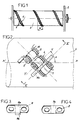
- the invention relates to roller conveyors C1, C2, Cn, composed of a frame 2 carrying rollers 3, parallel and horizontal, mounted free to rotate in this chassis and connected to means capable of driving them in rotation at the same speed or different speed.
- These means are, for example, constituted by pinions wedged on the shaft of each roller 3 and on which mesh chains or toothed belts 4.
- the device according to the invention which is included in a conveyor of the aforementioned type, comprises at least two rollers 5, of smaller diameter and each carrying a chain 6 with rollers 7, wound on its periphery.
- each chain is wound helically on a roller 5 extending from one of its ends to its other end.
- the helix angle a can vary from a few degrees to 60 °.
- This propeller can be wound to the right, that is to say going from left to right, or on the contrary to the left, that is to say going from right to left depending on the applications.
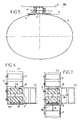
- each of the rollers 7 of the chain 6 is mounted to rotate freely on an axis 8 each of whose ends passes through one of the bearings of an internal link 9 and one of the bearings of a link external 10 on which it is riveted.
- the geometrical axis y'-y of each of the axes 8 is of course inclined at an angle a relative to the longitudinal axis x'-x of the roller 5, as shown in FIG. 2.
- each internal links 9 and external links 10 thereof are twisted, as shown in FIGS. 4 and 3 respectively.
- This twisting or warping angle is determined in relation to the angle of the winding propeller of the chain 6 on roller 5 and with the outside diameter of this roller.
- Figures 3 and 4 show that this twist only affects the ends of each of the links 9 and 10 which therefore keep a central part which is not twisted, respectively 9a, 10a.
- each of the outer links 10 is secured to a bent tab 10b which, when the link is assembled, protrudes outward and downward and allows to fix this link on the wall of the roller 5.
- this fixing is ensured by welding. It can be provided by bonding with a plastic roller.
- Figure 5 shows that the dimensions of the roller 5 and the rollers 7 are determined so that each roller 7 comes into contact with the load A, substantially in the horizontal contact plane PH of this load with normal rollers 3 of the conveyor.
- This figure also shows that, due to the warping given to the links, when a roller 7 is in position of contact with the load A, its axis of rotation y'-y is inclined by relative to the horizontal diametral plane H of the cylinder.
- this device comprises two rollers 5.
- These rollers are identical, say have 6 roller chains wound in the same direction and with the same winding angle. These chains are materialized by bars 6a representing their turns.
- Each of the rollers is connected to means rotational drive 4 which, in this embodiment, are common with those driving the normal rollers 3.
- the switching device consisting of the two rollers 5 is arranged at the end of the conveyor C1 and is associated with a fixed stop 13, arranged downstream of it and at the end of the conveyor C1.
- the device according to the invention is not disposed at the end of the conveyor C1 but in a section of it, so that this conveyor C1 extends beyond the referral device.
- This conveyor C1 is equipped with a stop 13a which, disposed downstream of the device, is retractable vertically.
- the stop 13a is in the lowered retracted position, that is to say below of the load movement plan on conveyor C1
- all load A circulating on this conveyor and arriving on the rollers 5 to chain rollers continues its rectilinear trajectory, represented by the arrow 14.
- the stop 13a By against, if the stop 13a is moved vertically to come into the trajectory of load A, this load is moved transversely on the conveyor C2, as shown by arrow 15.
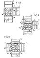
- the conveyor C1 is continuous and is associated with a transverse feed conveyor C3.
- the switching device comprises three rollers 5a including chains 6 with rollers 7 are wound with the same helix angle and with left hand propellers.
- the rollers 5a are driven in the same direction and at the same speed as the rollers 3 of conveyor C1.
- the device comprises a stop 13a, vertically retractable and arranged transversely to the trajectory of movement of the conveyor C1, downstream of the rollers 5a, and a fixed stop 16 arranged on the edge of the conveyor C1, which is opposite to the conveyor C3 and in the path of this conveyor C3.
- the lowering of the stop retractable 13a can be done automatically. It is the same for its elevation which can be triggered by passing the load over a contactor or a sensor arranged in the conveyor C3.
- the means of load retaining A constituted until now by stops are replaced by two other rollers 5b with roller chains arranged downstream, but next to the first rollers 5.
- the chains 6 to rollers 7 are wound in the opposite direction to those of rollers 5 and, by example, are wound with a helix on the left if the rollers 5 have a right propeller.
- these two rollers 5b are connected to means motors 20 which are separate from the means 4 ensuring the rotational drive rollers 5 and which, in addition, are reversible, that is to say can cause the rollers 5b in one direction or the other.
- Figure 10 shows the application of the device to a switch for cross crossing between a first conveyor C4 and a lateral conveyor C5 extended beyond the C4 conveyor by another C6 conveyor.
- the switching device is composed of two pairs of rollers rollers, namely two rollers 5c each carrying a chain 6 with rollers 7 helically wound with a left hand propeller and a pair of rollers 5d equipped with a roller chain helically wound on the right.
- the first pair of rollers 5c is rotated by the same means 4 as those driving the rollers 3 of the conveyor C4, while the rollers 5d are driven by separate and reversible means 20.
- the device according to the invention allows, for a small footprint, to make switches between conveyor for transferring, at a right angle or at any other angle, the loads from a conveyor.
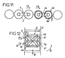
- the device according to the invention makes it possible to brake or slow down a load.
- Its 5th rollers are at less than two, and can therefore be more, and carry sections 6b of chains 6 which, wound on them with a zero helix angle, form spaced rings.
- the axis of the rollers 7 is therefore parallel to the axis of rotation of the 5th rollers.
- These rollers are rotated by motor means 24 which are independent for each roller and independent of the means 4 ensuring the rotation of normal rollers 3 of the conveyor.
- Each of these motor means 24 can drive one of the 5th rollers with a peripheral linear speed V2 which is different from the linear speed V1 rollers 3 and each of the following 5th rollers.
- rollers can alternatively be braking or accelerating.
- FIG. 12 shows the application of the device according to the invention to the modification of the orientation of a load on a conveyor.
- the device comprises, at least two rolls respectively upstream 5f and downstream 5g each carrying two sections of chains 6 wound in a helix, namely on the roller 5f, on its left side, a section 6c wound on the right, and, on its right-hand side, a section 6d wound at left, and for the 5g roll, on its left side, a 6th section wound at left and, on its right part, a section 6f wound on the right.
- the roller upstream 5f which is intended to pivot in the same direction and with the same speed that the normal rollers 3 of the conveyor, can be connected to the means 4 drive this conveyor or include motor means independent.
- the downstream roller 5g it is driven by means independent and reversible motors 20.
- This load can be rotated 90 ° or 180 °. She is useful, for example to orient the load in anticipation of the functions insured by a following post or in anticipation of its transfer to a transverse conveyor bringing it to a position requiring positioning different.
- the device according to the invention is simple and easy to make, can be adapted to existing conveyors and provides many applications modifying travel conditions of a load on a roller conveyor.
Applications Claiming Priority (2)
| Application Number | Priority Date | Filing Date | Title |
|---|---|---|---|
| FR9805218 | 1998-04-21 | ||
| FR9805218A FR2777552B1 (fr) | 1998-04-21 | 1998-04-21 | Dispositif pour modifier les conditions de deplacement d'une charge sur un convoyeur a rouleaux |
Publications (2)
| Publication Number | Publication Date |
|---|---|
| EP0952097A1 true EP0952097A1 (de) | 1999-10-27 |
| EP0952097B1 EP0952097B1 (de) | 2003-11-26 |
Family
ID=9525685
Family Applications (1)
| Application Number | Title | Priority Date | Filing Date |
|---|---|---|---|
| EP99420100A Expired - Fee Related EP0952097B1 (de) | 1998-04-21 | 1999-04-21 | Vorrichtung zur Änderung der Lastverschiebungskonditionen auf einem Rollenförderer |
Country Status (4)
| Country | Link |
|---|---|
| US (1) | US6116405A (de) |
| EP (1) | EP0952097B1 (de) |
| DE (1) | DE69913022D1 (de) |
| FR (1) | FR2777552B1 (de) |
Families Citing this family (6)
| Publication number | Priority date | Publication date | Assignee | Title |
|---|---|---|---|---|
| AT414329B (de) * | 2002-07-11 | 2007-09-15 | Tgw Transportgeraete Gmbh | Übergabeeinrichtung für stückhaftes fördergut |
| US6907978B2 (en) * | 2003-10-09 | 2005-06-21 | Lockheed Martin Corporation | Methods and apparatuses for inducting articles onto a conveyor |
| EP2508355B1 (de) * | 2011-04-07 | 2015-09-09 | Müller Martini Holding AG | Verfahren zum Entnehmen und/oder Zuführen zumindest eines Buchblocks aus einer bzw. in eine Förderstrecke einer Buchfertigungsstrasse, und Buchfertigungsstrasse |
| CN104411607A (zh) * | 2012-07-05 | 2015-03-11 | 莱特拉姆有限责任公司 | 旋转螺旋形件式移送机 |
| CN111850276B (zh) * | 2020-07-07 | 2021-12-24 | 鞍钢股份有限公司 | 一种钢管内表面淬火装置 |
| US11845613B1 (en) * | 2022-07-12 | 2023-12-19 | Intelligrated Headquarters, Llc | In-built divert elements for motorized conveyor rollers |
Citations (3)
| Publication number | Priority date | Publication date | Assignee | Title |
|---|---|---|---|---|
| US3356236A (en) * | 1965-08-05 | 1967-12-05 | Domino Sugar Company | Bi-directional cargo transfer unit |
| US3370685A (en) * | 1967-02-09 | 1968-02-27 | Score Ind | Diverter unit for roller conveyor |
| EP0781717A1 (de) * | 1995-12-28 | 1997-07-02 | Itoh Electric Company Limited | Fördervorrichtung |
Family Cites Families (2)
| Publication number | Priority date | Publication date | Assignee | Title |
|---|---|---|---|---|
| US3964588A (en) * | 1967-09-13 | 1976-06-22 | Kornylak Corporation | Conveyor having provision for discharging loads at an angle generally transverse to the line of travel or the conveyor |
| US5699892A (en) * | 1996-07-18 | 1997-12-23 | Industrial Technology Research Institute | Chain type transfer device |
-
1998
- 1998-04-21 FR FR9805218A patent/FR2777552B1/fr not_active Expired - Fee Related
-
1999
- 1999-04-19 US US09/293,929 patent/US6116405A/en not_active Expired - Fee Related
- 1999-04-21 DE DE69913022T patent/DE69913022D1/de not_active Expired - Lifetime
- 1999-04-21 EP EP99420100A patent/EP0952097B1/de not_active Expired - Fee Related
Patent Citations (3)
| Publication number | Priority date | Publication date | Assignee | Title |
|---|---|---|---|---|
| US3356236A (en) * | 1965-08-05 | 1967-12-05 | Domino Sugar Company | Bi-directional cargo transfer unit |
| US3370685A (en) * | 1967-02-09 | 1968-02-27 | Score Ind | Diverter unit for roller conveyor |
| EP0781717A1 (de) * | 1995-12-28 | 1997-07-02 | Itoh Electric Company Limited | Fördervorrichtung |
Also Published As
| Publication number | Publication date |
|---|---|
| DE69913022D1 (de) | 2004-01-08 |
| US6116405A (en) | 2000-09-12 |
| FR2777552B1 (fr) | 2000-07-28 |
| EP0952097B1 (de) | 2003-11-26 |
| FR2777552A1 (fr) | 1999-10-22 |
Similar Documents
| Publication | Publication Date | Title |
|---|---|---|
| EP0394124B1 (de) | Vorhang mit motorisierter Aufwickelvorrichtung | |
| EP0803464B1 (de) | Übertragungsvorrichtung, insbesondere für Fussgänger, zwischen zwei nacheinander in Reihe angeordneten, Förderungselementen, und Fördervorrichtung mit solcher Vorrichtung ausgestattet | |
| CH646922A5 (fr) | Dispositif pour le guidage longitudinal d'une bande sans fin. | |
| CA2470266A1 (fr) | Systeme de levage et de stabilisation d'un support de charge suspendu | |
| EP0952097B1 (de) | Vorrichtung zur Änderung der Lastverschiebungskonditionen auf einem Rollenförderer | |
| EP0462878B1 (de) | Stauförderer mit Arretiervorrichtung für Lastenträger am Übergangsbereich, Lastenträger und Lastenträgerzug für diese | |
| FR2607121A1 (fr) | Convoyeur a accumulation | |
| EP2189397B1 (de) | Lagerungsbehälter mit wieder verwendbaren Paletten | |
| EP0485797B1 (de) | Dreiteilige Staufalzvorrichtung | |
| FR2568848A1 (fr) | Derailleur arriere pour bicyclette | |
| EP1932042B1 (de) | Maschine zum legen eines optischen kabels um eine suspensionsader herum | |
| EP2115261B1 (de) | Vorrichtung mit einem Rollladen, der um eine Trommel gewickelt werden kann | |
| WO2003002435A2 (fr) | Dispositif de transport de pieces pour l'alimentation de machines | |
| EP0391804A1 (de) | Lade- und Entladevorrichtung für Rundballen aus Stroh oder Futter | |
| FR2581046A1 (fr) | Convoyeur continu perfectionne a palettes | |
| EP4306745A1 (de) | Stützwagen für ein beckenabdecksystem | |
| WO1988006553A1 (fr) | Dispositif de nouage d'un lien souple | |
| EP0570262B1 (de) | Fördervorrichtung für Lastträger | |
| WO1989000525A1 (fr) | Systeme de manutention rapide sur luges | |
| EP2076651A2 (de) | Tragebandwickelvorrichtung für einen roll-laden | |
| EP1932043A2 (de) | Selbstangetriebene verlegemaschine für optisches kabel | |
| FR3137936A1 (fr) | Système de recouvrement de bassin équipé d’un mécanisme de placage de couverture | |
| FR2631007A1 (fr) | Dispositif de centrage des tiges d'une chaine a tiges | |
| FR2689289A1 (fr) | Dispositif d'affichage à bande à structure de guidage. | |
| FR2588910A1 (fr) | Volet roulant pour fenetre |
Legal Events
| Date | Code | Title | Description |
|---|---|---|---|
| PUAI | Public reference made under article 153(3) epc to a published international application that has entered the european phase |
Free format text: ORIGINAL CODE: 0009012 |
|
| AK | Designated contracting states |
Kind code of ref document: A1 Designated state(s): DE ES FR GB IT |
|
| AX | Request for extension of the european patent |
Free format text: AL;LT;LV;MK;RO;SI |
|
| 17P | Request for examination filed |
Effective date: 20000412 |
|
| AKX | Designation fees paid |
Free format text: DE ES FR GB IT |
|
| 17Q | First examination report despatched |
Effective date: 20020312 |
|
| GRAH | Despatch of communication of intention to grant a patent |
Free format text: ORIGINAL CODE: EPIDOS IGRA |
|
| GRAS | Grant fee paid |
Free format text: ORIGINAL CODE: EPIDOSNIGR3 |
|
| GRAA | (expected) grant |
Free format text: ORIGINAL CODE: 0009210 |
|
| AK | Designated contracting states |
Kind code of ref document: B1 Designated state(s): DE ES FR GB IT |
|
| PG25 | Lapsed in a contracting state [announced via postgrant information from national office to epo] |
Ref country code: IT Free format text: LAPSE BECAUSE OF FAILURE TO SUBMIT A TRANSLATION OF THE DESCRIPTION OR TO PAY THE FEE WITHIN THE PRESCRIBED TIME-LIMIT;WARNING: LAPSES OF ITALIAN PATENTS WITH EFFECTIVE DATE BEFORE 2007 MAY HAVE OCCURRED AT ANY TIME BEFORE 2007. THE CORRECT EFFECTIVE DATE MAY BE DIFFERENT FROM THE ONE RECORDED. Effective date: 20031126 Ref country code: GB Free format text: LAPSE BECAUSE OF FAILURE TO SUBMIT A TRANSLATION OF THE DESCRIPTION OR TO PAY THE FEE WITHIN THE PRESCRIBED TIME-LIMIT Effective date: 20031126 |
|
| REG | Reference to a national code |
Ref country code: GB Ref legal event code: FG4D Free format text: NOT ENGLISH |
|
| REF | Corresponds to: |
Ref document number: 69913022 Country of ref document: DE Date of ref document: 20040108 Kind code of ref document: P |
|
| PG25 | Lapsed in a contracting state [announced via postgrant information from national office to epo] |
Ref country code: DE Free format text: LAPSE BECAUSE OF FAILURE TO SUBMIT A TRANSLATION OF THE DESCRIPTION OR TO PAY THE FEE WITHIN THE PRESCRIBED TIME-LIMIT Effective date: 20040227 |
|
| PG25 | Lapsed in a contracting state [announced via postgrant information from national office to epo] |
Ref country code: ES Free format text: LAPSE BECAUSE OF FAILURE TO SUBMIT A TRANSLATION OF THE DESCRIPTION OR TO PAY THE FEE WITHIN THE PRESCRIBED TIME-LIMIT Effective date: 20040309 |
|
| GBV | Gb: ep patent (uk) treated as always having been void in accordance with gb section 77(7)/1977 [no translation filed] |
Effective date: 20031126 |
|
| PLBE | No opposition filed within time limit |
Free format text: ORIGINAL CODE: 0009261 |
|
| STAA | Information on the status of an ep patent application or granted ep patent |
Free format text: STATUS: NO OPPOSITION FILED WITHIN TIME LIMIT |
|
| 26N | No opposition filed |
Effective date: 20040827 |
|
| PG25 | Lapsed in a contracting state [announced via postgrant information from national office to epo] |
Ref country code: FR Free format text: LAPSE BECAUSE OF NON-PAYMENT OF DUE FEES Effective date: 20041231 |
|
| REG | Reference to a national code |
Ref country code: FR Ref legal event code: ST |