EP0951700B1 - Verfahren zur stereoskopischen darstellung - Google Patents
Verfahren zur stereoskopischen darstellung Download PDFInfo
- Publication number
- EP0951700B1 EP0951700B1 EP98905232A EP98905232A EP0951700B1 EP 0951700 B1 EP0951700 B1 EP 0951700B1 EP 98905232 A EP98905232 A EP 98905232A EP 98905232 A EP98905232 A EP 98905232A EP 0951700 B1 EP0951700 B1 EP 0951700B1
- Authority
- EP
- European Patent Office
- Prior art keywords
- depth
- objects
- represented
- additional information
- space
- Prior art date
- Legal status (The legal status is an assumption and is not a legal conclusion. Google has not performed a legal analysis and makes no representation as to the accuracy of the status listed.)
- Expired - Lifetime
Links
Images

Classifications
-
- G—PHYSICS
- G06—COMPUTING OR CALCULATING; COUNTING
- G06T—IMAGE DATA PROCESSING OR GENERATION, IN GENERAL
- G06T15/00—Three-dimensional [3D] image rendering
- G06T15/10—Geometric effects
-
- H—ELECTRICITY
- H04—ELECTRIC COMMUNICATION TECHNIQUE
- H04N—PICTORIAL COMMUNICATION, e.g. TELEVISION
- H04N13/00—Stereoscopic video systems; Multi-view video systems; Details thereof
- H04N13/10—Processing, recording or transmission of stereoscopic or multi-view image signals
- H04N13/106—Processing image signals
- H04N13/128—Adjusting depth or disparity
-
- H—ELECTRICITY
- H04—ELECTRIC COMMUNICATION TECHNIQUE
- H04N—PICTORIAL COMMUNICATION, e.g. TELEVISION
- H04N13/00—Stereoscopic video systems; Multi-view video systems; Details thereof
- H04N13/10—Processing, recording or transmission of stereoscopic or multi-view image signals
- H04N13/106—Processing image signals
- H04N13/156—Mixing image signals
-
- H—ELECTRICITY
- H04—ELECTRIC COMMUNICATION TECHNIQUE
- H04N—PICTORIAL COMMUNICATION, e.g. TELEVISION
- H04N13/00—Stereoscopic video systems; Multi-view video systems; Details thereof
- H04N13/20—Image signal generators
- H04N13/275—Image signal generators from three-dimensional [3D] object models, e.g. computer-generated stereoscopic image signals
-
- H—ELECTRICITY
- H04—ELECTRIC COMMUNICATION TECHNIQUE
- H04N—PICTORIAL COMMUNICATION, e.g. TELEVISION
- H04N13/00—Stereoscopic video systems; Multi-view video systems; Details thereof
- H04N13/30—Image reproducers
- H04N13/332—Displays for viewing with the aid of special glasses or head-mounted displays [HMD]
- H04N13/344—Displays for viewing with the aid of special glasses or head-mounted displays [HMD] with head-mounted left-right displays
-
- H—ELECTRICITY
- H04—ELECTRIC COMMUNICATION TECHNIQUE
- H04N—PICTORIAL COMMUNICATION, e.g. TELEVISION
- H04N13/00—Stereoscopic video systems; Multi-view video systems; Details thereof
- H04N13/10—Processing, recording or transmission of stereoscopic or multi-view image signals
- H04N13/106—Processing image signals
- H04N13/122—Improving the three-dimensional [3D] impression of stereoscopic images by modifying image signal contents, e.g. by filtering or adding monoscopic depth cues
-
- H—ELECTRICITY
- H04—ELECTRIC COMMUNICATION TECHNIQUE
- H04N—PICTORIAL COMMUNICATION, e.g. TELEVISION
- H04N13/00—Stereoscopic video systems; Multi-view video systems; Details thereof
- H04N13/20—Image signal generators
- H04N13/286—Image signal generators having separate monoscopic and stereoscopic modes
-
- H—ELECTRICITY
- H04—ELECTRIC COMMUNICATION TECHNIQUE
- H04N—PICTORIAL COMMUNICATION, e.g. TELEVISION
- H04N13/00—Stereoscopic video systems; Multi-view video systems; Details thereof
- H04N13/30—Image reproducers
- H04N13/361—Reproducing mixed stereoscopic images; Reproducing mixed monoscopic and stereoscopic images, e.g. a stereoscopic image overlay window on a monoscopic image background
Definitions
- the invention relates to a method for graphic Representation of itself as a two-dimensional representation additional information available in addition to a stereoscopically represented space.
- EP 0 418 558 A2 or US 5,420,582 and US 5,289,185 a method and an Device for displaying flight guidance information with a spatial representation of the flight space with at least a horizon and the predicted trajectory of the Aircraft became known.
- the representation of the flight space can be different objects like the terrain, start and Runway or building included and in perspective displayed on a flat screen or stereoscopically become. To capture other ads at a glance too can, is the representation in the known device different scales on the screen than Additional information provided.
- the object of the present invention is in a stereoscopic representation of a room including an a two-dimensional additional information a reception to facilitate all information and a fatigue-free To enable working with such representations.
- the stereoscopically represented space in Looking in front of a vehicle, especially one Airplane, lies and stereoscopic objects contains which management information represents and where provide the additional information with a parallax and shown offset for the left and right eye be that they are at a depth of the depicted space are mapped, which are in a predetermined relationship the depth of objects present in the room shown stands.
- the Additional information is shown in a depth that in has a logical connection with the objects.
- All known are known as image display devices future facilities for stereoscopic reproduction suitable, for example at the head of the beholder via one eyepiece each Miniature screens, systems with all-round bezels, at which alternately the left and right eye unite Screen viewed, or systems with Glasses.
- the room including the one in it existing objects calculated by a graphics computer, so ultimately there is also information about the Importance or the attention value of the in the room existing objects.
- a scale in the level of Windshield of the vehicle can be shown.
- a representation of a Special attention for example one Runway, it may well be appropriate to use the scale including the associated pointer at the depth of the Show runway.
- the objects are a predictor represent the expected path of the vehicle referred to, and that the depth of the additional information in Range of the predictor.
- the predictor consist of several consecutive parts and that the depth of the Additional information in the area of a first, the vehicle the closest part.
- the depth of the additional information is changeable and to the depth of given objects is adjusted in the room.
- the vehicle in particular with one View of additional information from vehicles in the direction of travel together with fixed objects the vehicle and thus the To get closer to the viewer.
- one or more than predefined objects can be selected. The selection is made based on also stored in a computer Information. For example, one together with an indication of the depth approaching a waypoint jump to a following waypoint when the first waypoint is off out of sight.
- An advantageous embodiment of the invention Procedure is that particularly important Additional information is highlighted in that it in front of a stereoscopic screen Image display device are shown, that is between screen and viewer. It can also be provided that particularly important additional information are emphasized by the fact that they change with Depth, preferably with decreasing depth (the viewer oncoming).
- warning signals can be particularly clear compared to the other information presented be highlighted, if necessary in such a way that they are moving out of the depth of the image and the viewer almost "catch the eye".
- the task is solved, also behind to present objects lying to the viewer stereoscopically.
- objects can, for example, look from behind approaching aircraft.
- This training consists of that to represent additional objects that are behind the viewer are the additional objects a parallax and so for the left and right To be shown as staggered between the eye Viewer and appear on the screen.
- a better depth resolution of in particular far distant objects can be according to another training can be achieved by facing the depth of the room the reality is shown expanded that a Left and right eye images offset at least in part of the depth versus one is enlarged to scale.
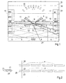
- Flight situation corresponds to a landing approach, whereby the predicted trajectory using one of four bodies 1, 2, 3, 4 existing predictors and lines 5, 6, 7, 8 as Limits of an approach channel which the aircraft is on approaches, are shown. With a further straight flight would the plane next to the just as rectangle 9 set up the runway shown.
- a line 10 represents the horizon, rectangles 11, 12 with their distance to the horizon 10 and with the inside of the rectangles visible digits indicate the pitch angle.
- the terrain 13 is provided with a grid 14, which in North-South direction is aligned.
- the sky is in shape of strips 15, 16, 17 with different hues (in Fig. 1 not visible, darker and lighter blue) to get further information about the pitch angle.
- the terrain 13 is preferably shown in green or brown.
- bodies 1 to 4 which are also predictor below colors and brightness values are provided, that stand out from both the sky and the terrain.
- the predictor shown in Fig. 1 has several Partial body divided bodies 1 to 4. A subdivision with individual lines, as shown in FIG. 1 was made, however, because of the resolution limits the display device and the human eye the given viewing distance is not clearly visible, especially in the most distant part of the body. In practice, therefore, the division into partial bodies is complete their shape or provided by a gradient.
- FIG. 2 In the side view of a Aircraft 21 and the body transformed into reality 2, 4 is the height of the body 2 and that in Fig. 2 is not visible body on the left side of the trajectory like this chosen that the upper edge 22 approximately at eye level of Pilots lies, while the lower edge 23 the height of the Footprint of the wheel 24 occupies.
- a line 26 indicates depth in the sense of distance from the viewer of the displays 18 to 21.
- FIG. 1 shows a perspective view Presentation, but the invention is based on a stereoscopic representation. Playing a such representation - which is the case for patent applications required paper form anyway only as two-dimensional Representation would be possible - essentially in that two partial images are generated, which are in the screen level not and with increasingly larger Distance from the viewer (depth) by a larger one Distinguish parallax. For example, the ads 18 to 21 in the same place for each of the drawing files shown, they appear infinitely wide to the viewer away, for example on the horizon.
- the Display in the depth range of the closest To arrange part 25 of the predictor.
- the parallax that is the horizontal offset from one field to another, the The display will therefore correspond to the parallax within the Depth range of the parts 25 of the Predictor selected.
- the screen image according to FIG. 1 provided that the approach channel 5 to 8 of the Runway 9 continues past the viewer.
- the in Parts of the approach channel located in the foreground of the image are accordingly closer to the viewer than the parts 25 of the predictor and thus also closer than that Displays 18 to 21.
- these are closer to the viewer than the horizon, so that they obscure the horizon; however, again covered by the lines of the approach channel become.
- a device for Implementation of the method according to FIG. 3 is for the representation of the flight space and the one in it located objects including the predictor 1 to 4 and approach channel 5 to 8 (FIG. 1) a graphics processor 31 provided, each a left and a right Generated partial image, which is stored in a memory 32, 33 each and an image display device 34, 35 are supplied.
- an image display device 34, 35 can be via a Eyepiece 36, 37 of left eye 38 and right eye 39 of one Be viewed.
- the graphics processor 31 generated signals L, R combined with signals L ', R', the are generated by a further graphics processor 42.
- This serves to generate the displays 18 to 21.
- the required elements are taken from a memory 43, while the sizes to be displayed (flight altitude, Flight speed, position, etc.) from sensors 44 to 46 are fed.
- the further graphics processor 42 receives from Graphics processor 31 information about the depth of the to be displayed - in the screen image according to FIG. 1 thus over the depth of the parts 25 of the predictor. Becomes for example in another flight situation Runway 9-related display from graphics processor 42 generated, the depth of the Runway 9 transmitted to further graphics processor 42. According to this information, this ad will then appear next to or shown above the runway.
- the embodiment shown schematically in Fig. 4 of the method according to the invention enables Visualization of objects, such as aircraft, which are outside of a viewer's viewing volume 53 51, especially behind the viewer.
- the Visible volume 53 results from the viewing distance of the Viewer 51 from screen 52 and screen size and the scaling of the displayed space.
- Within the Visible volume is in the case of the Embodiment according to Figures 1 and 2 among others the representation of the predictor 2, 4 and the displays 26.
- Visible volume 55 are detected, in which an aircraft 56th located.
- measures known per se such as Radar monitoring, communication systems between the Aircraft with each other and between the aircraft and Ground stations, the plane in which the Viewer 51 located, the position and location of the Aircraft 56 transmitted.
- the visible volume becomes 55 including the aircraft 56 in a scaled down Visible volume 55 'between the viewer 51 and the Screen 52 projected. It takes the place of Aircraft 56 is an aircraft symbol 56 'representing the position within the visible volume 55 and reflects the location.
Landscapes
- Engineering & Computer Science (AREA)
- Multimedia (AREA)
- Signal Processing (AREA)
- Physics & Mathematics (AREA)
- Geometry (AREA)
- Computer Graphics (AREA)
- General Physics & Mathematics (AREA)
- Theoretical Computer Science (AREA)
- Processing Or Creating Images (AREA)
- Testing, Inspecting, Measuring Of Stereoscopic Televisions And Televisions (AREA)
- Traffic Control Systems (AREA)
Abstract
Description
- Fig. 1
- ein Schirmbild zur Erläuterung der Erfindung,
- Fig. 2
- eine schematische Darstellung zur Erläuterung der Information des Schirmbildes,
- Fig. 3
- ein Blockschaltbild einer Einrichtung zur Durchführung des erfindungsgemäßen Verfahrens und
- Fig. 4
- eine schematische Darstellung einer weiteren Ausführungsform der Erfindung.
Claims (11)
- Verfahren zur graphischen Darstellung von an sich als zweidimensionale Darstellung vorliegenden Zusatzinformationen zusätzlich zu einem stereoskopisch dargestellten Raum, wobei der stereoskopisch dargestellte Raum in Blickrichtung vor einem Fahrzeug, insbesondere einem Flugzeug, liegt und stereoskopisch dargestellte Objekte enthält, welche Führungsinformationen darstellen und wobei die Zusatzinformationen mit einer Parallaxe versehen und derart für das linke und rechte Auge versetzt dargestellt werden, daß sie in einer Tiefe des dargestellten Raumes abgebildet werden, welche in einer vorgegebenen Beziehung zu der Tiefe von im dargestellten Raum vorhandenen Objekten steht.
- Verfahren nach Anspruch 1, dadurch gekennzeichnet, daß die Zusatzinformationen in einer Tiefe dargestellt sind, die in einem logischen Zusammenhang mit den Objekten steht.
- Verfahren nach Anspruch 2, dadurch gekennzeichnet, daß die Objekte einen Prädiktor darstellen, der die voraussichtliche Bahn des Fahrzeugs bezeichnet, und daß die Tiefe der Zusatzinformationen im Bereich des Prädiktors liegt.
- Verfahren nach Anspruch 3, dadurch gekennzeichnet, daß der Prädiktor aus mehreren hintereinanderliegenden Teilen besteht und daß die Tiefe der Zusatzinformationen im Bereich eines ersten, dem Fahrzeug nächstliegenden Teils liegt.
- Verfahren nach Anspruch 1, dadurch gekennzeichnet, daß die Tiefe der Zusatzinformationen veränderlich ist und an die Tiefe von vorgegebenen Objekten im Raum angepaßt wird.
- Verfahren nach Anspruch 5, dadurch gekennzeichnet, daß von mehreren Objekten im Raum ein oder mehrere als vorgegebene Objekte auswählbar sind.
- Verfahren nach einem der vorhergehenden Ansprüche, dadurch gekennzeichnet, daß besonders wichtige Zusatzinformationen dadurch hervorgehoben werden, daß sie vor dem Bildschirm einer stereoskopischen Bildwiedergabeeinrichtung dargestellt werden.
- Verfahren nach einem der vorhergehenden Ansprüche, dadurch gekennzeichnet, daß besonders wichtige Zusatzinformationen dadurch hervorgehoben werden, daß sie mit sich verändernder Tiefe, vorzugsweise mit abnehmender Tiefe (dem Betrachter entgegenkommend) dargestellt werden.
- Verfahren nach einem der vorhergehenden Ansprüche, dadurch gekennzeichnet, daß zur Darstellung von zusätzlichen Objekten, die sich hinter dem Betrachter befinden, die zusätzlichen Objekte mit einer Parallaxe versehen und derart für das linke und rechte Auge versetzt dargestellt werden, daß sie als zwischen dem Betrachter und dem Bildschirm befindlich erscheinen.
- Verfahren nach Anspruch 9, dadurch gekennzeichnet, daß ein die zusätzlichen Objekte umfassendes Sichtvolumen, das von einem hinter dem Betrachter liegenden Blickpunkt ausgehend bis zur Ebene des Bildschirms reicht, auf ein Sichtvolumen zwischen dem Betrachter und der Ebene des Bildschirms verkleinert wird.
- Verfahren nach einem der vorhergehenden Ansprüche, dadurch gekennzeichnet, daß die Tiefe des Raumes gegenüber der Realität dadurch aufgeweitet dargestellt wird, daß ein Versatz der Bilder für das linke und das rechte Auge mindestens in einem Teil der Tiefe gegenüber einer maßstäblichen Abbildung vergrößert ist.
Applications Claiming Priority (3)
| Application Number | Priority Date | Filing Date | Title |
|---|---|---|---|
| DE19700547 | 1997-01-10 | ||
| DE19700547A DE19700547B4 (de) | 1997-01-10 | 1997-01-10 | Verfahren zur stereoskopischen Darstellung |
| PCT/DE1998/000067 WO1998030981A1 (de) | 1997-01-10 | 1998-01-07 | Verfahren zur stereoskopischen darstellung |
Publications (2)
| Publication Number | Publication Date |
|---|---|
| EP0951700A1 EP0951700A1 (de) | 1999-10-27 |
| EP0951700B1 true EP0951700B1 (de) | 2003-11-26 |
Family
ID=7817061
Family Applications (1)
| Application Number | Title | Priority Date | Filing Date |
|---|---|---|---|
| EP98905232A Expired - Lifetime EP0951700B1 (de) | 1997-01-10 | 1998-01-07 | Verfahren zur stereoskopischen darstellung |
Country Status (4)
| Country | Link |
|---|---|
| EP (1) | EP0951700B1 (de) |
| CA (1) | CA2276105C (de) |
| DE (2) | DE19700547B4 (de) |
| WO (1) | WO1998030981A1 (de) |
Families Citing this family (4)
| Publication number | Priority date | Publication date | Assignee | Title |
|---|---|---|---|---|
| DE19831452C1 (de) * | 1998-07-14 | 2000-03-09 | Eurocopter Deutschland | Verfahren zur Unterstützung der Flugführung |
| ES2401512B1 (es) * | 2011-10-07 | 2014-02-25 | Ingenio 3000 Sl | Método para la modelización de pares estereoscópicos transversales en procesos fotogramétricos. |
| US10382746B1 (en) * | 2015-09-22 | 2019-08-13 | Rockwell Collins, Inc. | Stereoscopic augmented reality head-worn display with indicator conforming to a real-world object |
| US10853014B2 (en) | 2018-04-17 | 2020-12-01 | Rockwell Collins, Inc. | Head wearable device, system, and method |
Family Cites Families (6)
| Publication number | Priority date | Publication date | Assignee | Title |
|---|---|---|---|---|
| JPS6030650B2 (ja) * | 1979-10-26 | 1985-07-17 | 日本油脂株式会社 | 座薬基剤組成物 |
| US5020878A (en) * | 1989-03-20 | 1991-06-04 | Tektronix, Inc. | Method and apparatus for generating a binocular viewing model automatically adapted to a selected image |
| DE3930862A1 (de) * | 1989-09-15 | 1991-03-28 | Vdo Schindling | Verfahren und einrichtung zur darstellung von flugfuehrungsinformation |
| FR2666428B1 (fr) * | 1990-09-05 | 1994-09-23 | Aerospatiale | Procede de visualisation sur un ecran a bord d'un avion, de symboles d'aide au pilotage. |
| DE4314811A1 (de) * | 1993-05-05 | 1994-12-08 | Vdo Luftfahrtgeraete Werk Gmbh | Verfahren zur Darstellung von Flugführungsinformationen |
| US6198484B1 (en) * | 1996-06-27 | 2001-03-06 | Kabushiki Kaisha Toshiba | Stereoscopic display system |
-
1997
- 1997-01-10 DE DE19700547A patent/DE19700547B4/de not_active Expired - Fee Related
-
1998
- 1998-01-07 EP EP98905232A patent/EP0951700B1/de not_active Expired - Lifetime
- 1998-01-07 CA CA002276105A patent/CA2276105C/en not_active Expired - Fee Related
- 1998-01-07 WO PCT/DE1998/000067 patent/WO1998030981A1/de not_active Ceased
- 1998-01-07 DE DE59810276T patent/DE59810276D1/de not_active Expired - Lifetime
Also Published As
| Publication number | Publication date |
|---|---|
| DE19700547B4 (de) | 2004-11-18 |
| CA2276105A1 (en) | 1998-07-16 |
| WO1998030981A1 (de) | 1998-07-16 |
| DE19700547A1 (de) | 1998-07-23 |
| EP0951700A1 (de) | 1999-10-27 |
| CA2276105C (en) | 2006-10-10 |
| DE59810276D1 (de) | 2004-01-08 |
Similar Documents
| Publication | Publication Date | Title |
|---|---|---|
| EP0697098B1 (de) | Verfahren zur darstellung von flugführungsinformationen | |
| DE3737972C2 (de) | ||
| DE102010016043B4 (de) | Anzeigevorrichtung und Messvorrichtung für ein Fahrzeug und Verfahren zum Anzeigen eines Fahrzeugzustands | |
| DE102018215292B4 (de) | Verfahren zum Darstellen einer Fahrzeugumgebung in einem Fahrzeug und zugehörige Vorrichtung | |
| DE69113199T2 (de) | Verfahren und Gerät zur Erzeugung einer tragbaren optischen Anzeige. | |
| DE60206052T2 (de) | System und verfahren zur bearbeitung von flugplandaten | |
| EP0805362B1 (de) | Verfahren zur Hinderniswarnung für tieffliegende Fluggeräte | |
| EP1972896B1 (de) | Mensch-Maschinen-Interface zur Pilotenunterstützung bei Start und Landung eines Fluggerät bei verminderter Außensicht | |
| EP0418558A2 (de) | Verfahren und Einrichtung zur Darstellung von Flugführungsinformation | |
| DE112014005487T5 (de) | Graphische Anzeigeinstrument-Vorrichtung | |
| DE102018201768B4 (de) | Verfahren zum Anzeigen von Informationen in einem Head-Up-Display eines Fahrzeugs, Anzeigesystem für ein Fahrzeug und Fahrzeug mit einem Anzeigesystem | |
| DE10102938B4 (de) | Nicklage-Symbolik | |
| DE60303639T2 (de) | Verfahren zur Synthese eines dreidimensionalen Sichtbarkeitsbildes | |
| DE112019000329B4 (de) | Anzeigesystem, bewegliches objekt und gestaltungsverfahren | |
| DE102017209802A1 (de) | Verfahren und Vorrichtung zum Betreiben eines Anzeigesystems mit einer Datenbrille | |
| DE112014006991B4 (de) | Zeichensteuervorrichtung | |
| DE3323460A1 (de) | Verfahren und einrichtung zur optischen simulation einer szenen-fortbewegung | |
| DE602005005907T2 (de) | Verfahren zur Anzeige von Karteninformationen und von Aeronautikzonen auf einer Flugzeuganzeige | |
| DE102006059922A1 (de) | Verfahren zum Darstellen eines Kartenausschnittes in einem Navigationssystem und Navigationssystem | |
| DE19700547B4 (de) | Verfahren zur stereoskopischen Darstellung | |
| DE3210694C2 (de) | ||
| DE102013019144B4 (de) | Head-up-Display für ein Fahrzeug und Verfahren zum Bereitstellen eines elektronischen Bildsignals für ein Head-up-Display | |
| EP1084380B1 (de) | Verfahren zur darstellung von gelände | |
| DE102014104572A1 (de) | Geschwindigkeitsanzeige | |
| DE19836002B4 (de) | Stereoskopische Flugführungshilfe |
Legal Events
| Date | Code | Title | Description |
|---|---|---|---|
| PUAI | Public reference made under article 153(3) epc to a published international application that has entered the european phase |
Free format text: ORIGINAL CODE: 0009012 |
|
| 17P | Request for examination filed |
Effective date: 19990610 |
|
| AK | Designated contracting states |
Kind code of ref document: A1 Designated state(s): DE FR GB IT |
|
| RAP1 | Party data changed (applicant data changed or rights of an application transferred) |
Owner name: DIEHL AVIONIK SYSTEME GMBH |
|
| 17Q | First examination report despatched |
Effective date: 20020313 |
|
| GRAH | Despatch of communication of intention to grant a patent |
Free format text: ORIGINAL CODE: EPIDOS IGRA |
|
| GRAS | Grant fee paid |
Free format text: ORIGINAL CODE: EPIDOSNIGR3 |
|
| GRAA | (expected) grant |
Free format text: ORIGINAL CODE: 0009210 |
|
| AK | Designated contracting states |
Kind code of ref document: B1 Designated state(s): DE FR GB IT |
|
| REG | Reference to a national code |
Ref country code: GB Ref legal event code: FG4D Free format text: NOT ENGLISH |
|
| GBT | Gb: translation of ep patent filed (gb section 77(6)(a)/1977) |
Effective date: 20031128 |
|
| REF | Corresponds to: |
Ref document number: 59810276 Country of ref document: DE Date of ref document: 20040108 Kind code of ref document: P |
|
| ET | Fr: translation filed | ||
| PLBE | No opposition filed within time limit |
Free format text: ORIGINAL CODE: 0009261 |
|
| STAA | Information on the status of an ep patent application or granted ep patent |
Free format text: STATUS: NO OPPOSITION FILED WITHIN TIME LIMIT |
|
| 26N | No opposition filed |
Effective date: 20040827 |
|
| PGFP | Annual fee paid to national office [announced via postgrant information from national office to epo] |
Ref country code: FR Payment date: 20120206 Year of fee payment: 15 |
|
| PGFP | Annual fee paid to national office [announced via postgrant information from national office to epo] |
Ref country code: GB Payment date: 20120120 Year of fee payment: 15 Ref country code: IT Payment date: 20120126 Year of fee payment: 15 |
|
| PGFP | Annual fee paid to national office [announced via postgrant information from national office to epo] |
Ref country code: DE Payment date: 20120321 Year of fee payment: 15 |
|
| GBPC | Gb: european patent ceased through non-payment of renewal fee |
Effective date: 20130107 |
|
| REG | Reference to a national code |
Ref country code: FR Ref legal event code: ST Effective date: 20130930 |
|
| PG25 | Lapsed in a contracting state [announced via postgrant information from national office to epo] |
Ref country code: DE Free format text: LAPSE BECAUSE OF NON-PAYMENT OF DUE FEES Effective date: 20130801 |
|
| REG | Reference to a national code |
Ref country code: DE Ref legal event code: R119 Ref document number: 59810276 Country of ref document: DE Effective date: 20130801 |
|
| PG25 | Lapsed in a contracting state [announced via postgrant information from national office to epo] |
Ref country code: FR Free format text: LAPSE BECAUSE OF NON-PAYMENT OF DUE FEES Effective date: 20130131 Ref country code: GB Free format text: LAPSE BECAUSE OF NON-PAYMENT OF DUE FEES Effective date: 20130107 |
|
| PG25 | Lapsed in a contracting state [announced via postgrant information from national office to epo] |
Ref country code: IT Free format text: LAPSE BECAUSE OF NON-PAYMENT OF DUE FEES Effective date: 20130107 |