EP0951125A2 - Muffenkörper zum Abdecken von Kabeladerendabschnitten - Google Patents
Muffenkörper zum Abdecken von Kabeladerendabschnitten Download PDFInfo
- Publication number
- EP0951125A2 EP0951125A2 EP99107222A EP99107222A EP0951125A2 EP 0951125 A2 EP0951125 A2 EP 0951125A2 EP 99107222 A EP99107222 A EP 99107222A EP 99107222 A EP99107222 A EP 99107222A EP 0951125 A2 EP0951125 A2 EP 0951125A2
- Authority
- EP
- European Patent Office
- Prior art keywords
- sleeve body
- opening
- sleeve
- body according
- cables
- Prior art date
- Legal status (The legal status is an assumption and is not a legal conclusion. Google has not performed a legal analysis and makes no representation as to the accuracy of the status listed.)
- Withdrawn
Links
- 239000004020 conductor Substances 0.000 title description 19
- 229920002379 silicone rubber Polymers 0.000 claims description 4
- 239000004945 silicone rubber Substances 0.000 claims description 4
- 229920001971 elastomer Polymers 0.000 description 2
- 239000000806 elastomer Substances 0.000 description 2
- 238000000034 method Methods 0.000 description 2
- RYGMFSIKBFXOCR-UHFFFAOYSA-N Copper Chemical compound [Cu] RYGMFSIKBFXOCR-UHFFFAOYSA-N 0.000 description 1
- 230000005540 biological transmission Effects 0.000 description 1
- 230000006835 compression Effects 0.000 description 1
- 238000007906 compression Methods 0.000 description 1
- 229910052802 copper Inorganic materials 0.000 description 1
- 239000010949 copper Substances 0.000 description 1
- 238000011161 development Methods 0.000 description 1
- 230000018109 developmental process Effects 0.000 description 1
- 239000004744 fabric Substances 0.000 description 1
- 238000009499 grossing Methods 0.000 description 1
- 239000002198 insoluble material Substances 0.000 description 1
- 238000009413 insulation Methods 0.000 description 1
- 239000012212 insulator Substances 0.000 description 1
- 239000000463 material Substances 0.000 description 1
- 238000005259 measurement Methods 0.000 description 1
- 239000004033 plastic Substances 0.000 description 1
- 230000001681 protective effect Effects 0.000 description 1
- 239000000126 substance Substances 0.000 description 1
Images


Classifications
-
- H—ELECTRICITY
- H02—GENERATION; CONVERSION OR DISTRIBUTION OF ELECTRIC POWER
- H02G—INSTALLATION OF ELECTRIC CABLES OR LINES, OR OF COMBINED OPTICAL AND ELECTRIC CABLES OR LINES
- H02G15/00—Cable fittings
- H02G15/08—Cable junctions
- H02G15/18—Cable junctions protected by sleeves, e.g. for communication cable
- H02G15/184—Cable junctions protected by sleeves, e.g. for communication cable with devices for relieving electrical stress
-
- H—ELECTRICITY
- H02—GENERATION; CONVERSION OR DISTRIBUTION OF ELECTRIC POWER
- H02G—INSTALLATION OF ELECTRIC CABLES OR LINES, OR OF COMBINED OPTICAL AND ELECTRIC CABLES OR LINES
- H02G15/00—Cable fittings
- H02G15/08—Cable junctions
- H02G15/18—Cable junctions protected by sleeves, e.g. for communication cable
- H02G15/184—Cable junctions protected by sleeves, e.g. for communication cable with devices for relieving electrical stress
- H02G15/188—Cable junctions protected by sleeves, e.g. for communication cable with devices for relieving electrical stress connected to a cable shield only
Definitions
- the invention relates to a sleeve body for covering cable end sections in a branch sleeve for cables - preferably for medium voltage cables - with at least one cable core.
- a one-piece sleeve body is known, with a body made of insulating Elastomer in which at least one conductive elastomer is concentrically integrated and made of a support body that can be shrunk by thermal or chemical influences, which can be removed by means of insoluble Material connection is connected to the insulating body, with the support body on the outside the insulator.
- the support body is an externally accessible conductor, preferably a Fabric hose, integrated.
- the sleeve body is used as a connecting sleeve for two single-core medium voltage cables can be used (DE 195 32 559 C2).
- DE-AS 25 55 653 describes an end fitting especially for three-wire cables.
- Individual field control elements are designed as hollow cylinders and in one piece with an inner diameter connected to the outer diameter of the cable jacket cap. The individual elements can be used for different conductor cross-sections. With this set is the adapted cap necessary, which is part of the distribution housing and at the same time represents a seal.
- the invention consists essentially in an elastic sleeve body, in which to cover the wire end sections are formed at least two bushings for the wire end sections and a field control element is integrated in the sleeve body for each bushing.
- pre-designed plug-in elements do not have to be used in that the simple sleeve body according to the invention on site without cumbersome preparation can be used and that by using the slide-on technology or cold shrink technology a relatively large diameter range or power range of a wire connection covered can be.
- the sleeve body is preferably made of silicone rubber. As is known, the sleeve body can be widened are held on a removable support body for assembly. To simplify the Removing the sleeve body from the support body should facilitate sliding on the support body Layer be applied.
- An elastic sleeve pipe can also be used together with the sleeve body. With this sleeve pipe an external pressure can be generated on the sleeve body, so that in particular sleeve body and field control elements completely cover the wire end sections without cavities and there is even internal pressure all around on the wire end sections.
- the invention preferably has the following features.
- the field controls are vulcanized or glued in.
- the conductor feedthroughs in the socket body can vary depending on the space requirement or geometric Arrangement of the conductors in the branch sleeve parallel to each other or different from a parallel one Be led course.
- the conductor bushings can preferably have a course converging to a point.
- Embodiments with non-parallel The course of the bushings has when installing cables with very large conductor cross sections the advantage that the conductor ends do not have to be bent or arranged in parallel.
- the sleeve body can have an oval outer shape or a circular shape. Has an oval shape on the one hand the advantage of material spam, on the other hand by using the mentioned additional elastic sleeve pipe an optimal pressure transfer to the cable end sections because the ovality favors pressure transmission.
- the sleeve body is made up of at least two identical parts, each part being one Conductor bushing is assigned and comprises a field control element. So the field control is in one piece and not divided. An external pressure is applied with the elastic sleeve pipe used generates the sleeve body, which in particular contributes to the fact that the parts of the sleeve body itself join together without voids.
- the sleeve body is divided in its longitudinal axis; so parallel to the arrangement of the bushings.
- the division of the sleeve body is such that the separating surface in cross section (in vertical supervision) has an S shape.
- the sleeve body according to the invention can be used in various connection bodies in medium-voltage technology be used. It is preferably proposed that the sleeve body in a cable plug part to be used for medium voltage cables. Such cable plug-in parts can be used, for example be equipped with a capacitive adapter, with which voltage or earthing measurements can be carried out are.
- the plug body has a first opening in the axial Course of a device connection part and a second opening opening into this for the cable connection. In the first opening there is a grub screw for electrical and mechanical connection arranged the device connection part for the cable connection, with at least two cables in the guided second opening and are connected in the first opening with the threaded pin.
- the cables are offset in the area of the second opening and in a common field control body with two Passages arranged according to the invention and performed separately in this.
- FIG. 1 shows a longitudinal section of a socket body 10 with two conductor bushings 13 ', 13' '.
- the longitudinal structure corresponds to that of known sleeve bodies with a field control element.
- the up on the insulation stripped cable end sections 14.1,15.1,15.2 are inserted from the left, in the area of the field control elements 16 16 ', the non-removed conductive layer of the cable end sections comes to rest.
- the enlarged bores 12 ', 12' 'of the bushings come to lie over the wire shield.
- FIG. 2A and 2B cross sections of a sleeve body 10 are shown, in Fig. 2A an oval Outer shape and in Fig. 2B there is a circular outer shape.
- Fig. 2B there is also a division of the sleeve body 10 in two halves 101, 102 visible. The division is such that the interface in Cross-section (perpendicular to the longitudinal direction of the socket body) has an S-shape.
- a field control element is integrated.
- FIG. 3A and 3B each show an embodiment of a split sleeve body, with FIG. 3A one Perspective representation of the sleeve body according to Fig. 2B repeated.
- the division of the socket body is preferably chosen so that two sleeve body halves (101, 110) together form a whole body form that does not consist of different halves.
- Fig. 3B it is clear that in a A body control element 16 is integrated into the sleeve body half 110.
- FIG. 4 shows a longitudinal section through a further sleeve body 20 in which the conductor bushings 13 ', 13' 'do not have a parallel but a converging course to a point.
- the convergence angle W (see also FIG. 6B) is preferably based on the space available or the predetermined geometric arrangement of the conductor ends in the branch sleeve. Otherwise corresponds the structure of that of a sleeve body according to FIG. 1.
- FIG. 5 shows an oval belonging to FIG. 4 Cross section of the sleeve body 20.
- FIG. 6A and 6B each show a field control element 18, 18 ', which is made of conductive silicone rubber Can be produced by the usual method and integrated into the socket body according to the invention is.
- the cross section of a field control element 18 is shown in FIG. 6A.
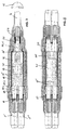
- Fig. 7 shows the assembly of a branch of a cable 4 coming from the right.
- the power line branches into the two outgoing cables 5 'and 5' '.
- All cable cores are known as their ends and the conductors 14 '; 15' are electrically contacted in a metallic conductor connector 40.
- the conductor connection is covered by two half shells 42.
- the invention Sleeve bodies cover the cable wire ends of cables 5 'and 5' 'on the left.
- the single wire 14 'on the right is field-controlled closed by a slide-on body 30 known in the embodiment.
- the entire arrangement is covered by an elastic sleeve pipe 44, which in the area of Contact half-shells 42 also includes field control parts 43.
- As a protective outer shell is a Outer jacket 50 applied, under which there is also a connection of the cable shields.
- Fig. 8 shows a cable connection as a double or H branch. The details largely correspond the cable connection of Fig. 7. The main difference is that on both Sides in the branch sleeve an inventive sleeve body 10 is used and that the conductor connector 41 is designed for contacting two conductors 14 'and 15'.
- FIG. 9 shows a cable plug-in part 52 for two medium-voltage cables arranged on a device connection part 51 53 shown.
- the cable plug part 52 has one provided with an outer conductive layer Plug body 54 made of silicone rubber with a first opening 55 in the axial course of the device connection part 51 and a second opening 56 for connecting the two cables 53.
- Plug bodies 54 are in the area of the opening 56 and in their mouth area in the opening 55 field smoothing sleeves 57 integrated.
- a grub screw 58 is arranged, which in the device connection part 51 is screwed and on which the provided with holes for the threaded pin 58 Terminal lugs 59 of two, each at the end of the conductor 53 a of the remote cable 53 arranged compression cable lugs 60 are arranged.
- connection flags 59 are by a clamping nut 62 which on a spring ring 63 and a washer 64 on the Device connecting part 51 attacks terminal lug 59, fixed to the device connecting part 51.
- the plug body 54 is provided with a tension-proof screw insert 65 and a cover cap 66 completed.
- the cables 53 are in a common field control body which is firmly enclosed by the plug body 54 67 with a round or oval cross section and two bushings 13 ', 13' 'and managed separately.
- a Grounding clamp 68 is arranged, via which the conductive layer is grounded.
Landscapes
- Cable Accessories (AREA)
Abstract
Description

Claims (11)
- Muffenkörper zum Abdecken von Kabeladerendabschnitten (14.1,15.1,15.2) in einer Abzweigmuffe für Kabel - vorzugsweise für Mittelspannungskabel - mit mindestens einer Kabelader (4), wobei der Muffenkörper (10,20) als elastischer Körper mit mindestens zwei Durchführungen (13',13'') ausgebildet ist und im Muffenkörper (10,20) für jede Durchführung (13', 13'') ein Feldsteuerelement (16,18, 18') integriert ist.
- Muffenkörper nach Anspruch 1, dadurch gekennzeichnet, daß die Feldsteuerelemente (16,18, 18') einvulkanisiert oder eingeklebt sind.
- Muffenkörper nach Anspruch 1 oder 2, dadurch gekennzeichnet, daß die Durchführungen (13', 13'') im Muffenkörper (10,20) parallel nebeneinander geführt sind.
- Muffenkörper nach Anspruch 1 oder 2, dadurch gekennzeichnet, daß die Durchführungen (13', 13'') im Muffenkörper (10,20) nebeneinander abweichend von einem parallelen Verlauf geführt sind.
- Muffenkörper nach Anspruch 4, dadurch gekennzeichnet, daß die Durchführungen (13',13'') einen auf einen Punkt konvergierenden Verlauf haben.
- Muffenkörper nach einem der vorhergehenden Ansprüche, dadurch gekennzeichnet, daß der Muffenkörper (10,20) eine ovale Außenform hat.
- Muffenkörper nach einem der vorhergehenden Ansprüche, dadurch gekennzeichnet, daß der Muffenkörper (10,20) aus mindestens zwei identischen Teilen (101,110) aufgebaut ist, wobei jedem Teil eine Durchführung (13') zugeordnet ist und jedes Teil ein Feldsteuerelement (16) umfaßt.
- Muffenkörper nach Anspruch 7, dadurch gekennzeichnet, daß der Muffenkörper (10,20) in seiner Längsachse geteilt ist.
- Muffenkörper nach Anspruch 8, dadurch gekennzeichnet, daß die Teilung des Muffenkörpers (10,20) derart ist, daß die Trennfläche im Querschnitt senkrecht zur Längsachse eine S-Form hat.
- Muffenkörper nach einem der vorhergehenden Ansprüche, dadurch gekennzeichnet, daß der Muffenkörper (10,20) aus Silikonkautschuk ist.
- Verwendung eines Muffenkörpers nach einem der vorhergehenden Ansprüche, in einem Kabelsteckteil für Mittelspannungskabel mit einem Steckerkörper mit einer ersten Öffnung (55) im axialen Verlauf eines Geräteanschlußteiles (51) und einer in diese mündenden zweiten Öffnung (56) für den Kabelanschluß, einem in der ersten Öffnung (55) angeordneten Gewindestift (58) zur elektrischen und mechanischen Verbindung mit dem Geräteanschlußteil (51) für den Kabelanschluß, wobei wenigstens zwei Kabel (53) in der zweiten Öffnung (56) geführt und in der ersten Öffnung (55) mit dem Gewindestift (58) verbunden sind, wobei die Kabel (53) im Bereich der zweiten Öffnung (56) abgesetzt und in einem gemeinsamen Feldsteuerkörper (67) angeordnet und separat in diesem geführt sind.
Applications Claiming Priority (4)
| Application Number | Priority Date | Filing Date | Title |
|---|---|---|---|
| DE19817219 | 1998-04-17 | ||
| DE1998117219 DE19817219C1 (de) | 1998-04-17 | 1998-04-17 | Muffenkörper zum Abdecken von Kabeladerendabschnitten |
| DE19845005 | 1998-10-01 | ||
| DE1998145005 DE19845005C1 (de) | 1998-10-01 | 1998-10-01 | Kabelsteckteil für Mittelspannungskabel |
Publications (2)
| Publication Number | Publication Date |
|---|---|
| EP0951125A2 true EP0951125A2 (de) | 1999-10-20 |
| EP0951125A3 EP0951125A3 (de) | 2001-11-28 |
Family
ID=26045576
Family Applications (1)
| Application Number | Title | Priority Date | Filing Date |
|---|---|---|---|
| EP99107222A Withdrawn EP0951125A3 (de) | 1998-04-17 | 1999-04-14 | Muffenkörper zum Abdecken von Kabeladerendabschnitten |
Country Status (2)
| Country | Link |
|---|---|
| EP (1) | EP0951125A3 (de) |
| CZ (1) | CZ133599A3 (de) |
Cited By (1)
| Publication number | Priority date | Publication date | Assignee | Title |
|---|---|---|---|---|
| EP1995841A1 (de) | 2007-05-22 | 2008-11-26 | Tyco Electronics Raychem GmbH | Vorrichtung zur Verwendung in einer Kabelverbindungsanordnung mit einer derartigen Vorrichtung |
Family Cites Families (7)
| Publication number | Priority date | Publication date | Assignee | Title |
|---|---|---|---|---|
| DE2555653C2 (de) * | 1975-12-11 | 1977-09-22 | Feiten & Guilleaume Carlswerk AG, 5000 Köln | Endverschlußgarnitur für kunststoffisolierte Mehrleiter-Starkstromkabel mit unterschiedlichen Feldbegrenzungen |
| DE3433464A1 (de) * | 1984-09-12 | 1986-03-20 | Felten & Guilleaume Energietechnik GmbH, 5000 Köln | Aufschiebbare muffe fuer mittelspannungskabel |
| DE8804221U1 (de) * | 1988-03-29 | 1988-05-11 | Felten & Guilleaume Energietechnik AG, 5000 Köln | Aufschiebbare Reparaturmuffe für Kunststoffisolierte Kabel |
| FR2686195B1 (fr) * | 1992-01-09 | 1995-02-10 | Pirelli Cables Sa | Dispositif pour raccorder de facon demontable des cables electriques en moyenne tension. |
| DE4432542C2 (de) * | 1994-09-13 | 1997-10-02 | Rheydt Kabelwerk Ag | Steckendverschluß |
| DE19532559C2 (de) * | 1995-09-04 | 1997-07-03 | Felten & Guilleaume Energie | Einteiliger Muffenkörper |
| WO1999021259A1 (en) * | 1997-10-22 | 1999-04-29 | Minnesota Mining And Manufacturing Company | Improved medium voltage branch splice and method of making the same |
-
1999
- 1999-04-14 EP EP99107222A patent/EP0951125A3/de not_active Withdrawn
- 1999-04-15 CZ CZ991335A patent/CZ133599A3/cs unknown
Cited By (1)
| Publication number | Priority date | Publication date | Assignee | Title |
|---|---|---|---|---|
| EP1995841A1 (de) | 2007-05-22 | 2008-11-26 | Tyco Electronics Raychem GmbH | Vorrichtung zur Verwendung in einer Kabelverbindungsanordnung mit einer derartigen Vorrichtung |
Also Published As
| Publication number | Publication date |
|---|---|
| CZ133599A3 (cs) | 1999-11-17 |
| EP0951125A3 (de) | 2001-11-28 |
Similar Documents
| Publication | Publication Date | Title |
|---|---|---|
| DE69704866T2 (de) | Elektrischer verbinder | |
| US3800064A (en) | Universal power cable joint with closed-cell sponge stress relief element | |
| EP3590162B1 (de) | Haltevorrichtung zum halten eines geschirmten kabels | |
| DE202017101060U1 (de) | Steckverbinder, insbesondere für eine Hochstromanwendung | |
| DE2132418A1 (de) | Spleissverbinder fuer Hochspannungskabel | |
| WO2019057239A1 (de) | Hochstromsteckverbinder mit isolierhülse | |
| EP0114244B1 (de) | Kabelverteiler, bzw. -abzweiger für Breitbandkommunikationskoaxialkabel | |
| DE102022122506A1 (de) | Universell einsetzbares Gehäuse zur Abdeckung von Kontaktelementen | |
| EP2099099B1 (de) | Elektrisches Kupplungsteil mit angeschlossener elektrischer Leitung | |
| DE102023209887B4 (de) | Kontaktanbindung für eine elektrische Leitung | |
| DE3347170C2 (de) | ||
| DE3439156A1 (de) | Hochspannungsbauteil | |
| WO2001091262A2 (de) | Muffenisolierkörper mit schraubverbinder zur herstellung einer kabelverbindung für mittelspannungs-kunststoffkabel | |
| DE102008054585B4 (de) | Winkelsteckverbindung für geschirmte Kabel | |
| DE3041337C2 (de) | ||
| DE4403571C1 (de) | Verbindungsmuffe für kunststoffisolierte Hochspannungsenergieversorgungskabel | |
| EP3477777A1 (de) | Elektrische leitung mit schirmausleitung | |
| DE19845006C1 (de) | Oberirdische Kabelverbindung | |
| EP0773601A2 (de) | Sicherheitssteckverbindung | |
| DE3042595A1 (de) | Aufschiebbare, mit geteiltem isolierkoerper versehene verbindungsmuffe fuer kunststoffisolierte mittelspannungskabel | |
| DE10138728A1 (de) | Kupplungselement zur Anbringung an einer geschirmten elektrischen Leitung und Verfahren zu seiner Anbringung an einer Leitung | |
| EP0017953A1 (de) | Garnitur für das Ende eines Mittelspannungs- oder Hochspannungskabels | |
| DE19817219C1 (de) | Muffenkörper zum Abdecken von Kabeladerendabschnitten | |
| DE19856025C2 (de) | Kompakte Übergangsmuffe | |
| EP0508322B1 (de) | Übergangsmuffe |
Legal Events
| Date | Code | Title | Description |
|---|---|---|---|
| PUAI | Public reference made under article 153(3) epc to a published international application that has entered the european phase |
Free format text: ORIGINAL CODE: 0009012 |
|
| AK | Designated contracting states |
Kind code of ref document: A2 Designated state(s): AT BE CH CY DE DK ES FI FR GB GR IE IT LI LU MC NL PT SE Kind code of ref document: A2 Designated state(s): AT BE CH DE LI NL |
|
| AX | Request for extension of the european patent |
Free format text: AL;LT;LV;MK;RO;SI |
|
| PUAL | Search report despatched |
Free format text: ORIGINAL CODE: 0009013 |
|
| AK | Designated contracting states |
Kind code of ref document: A3 Designated state(s): AT BE CH CY DE DK ES FI FR GB GR IE IT LI LU MC NL PT SE |
|
| AX | Request for extension of the european patent |
Free format text: AL;LT;LV;MK;RO;SI |
|
| AKX | Designation fees paid |
Free format text: AT BE CH DE LI NL |
|
| STAA | Information on the status of an ep patent application or granted ep patent |
Free format text: STATUS: THE APPLICATION IS DEEMED TO BE WITHDRAWN |
|
| 18D | Application deemed to be withdrawn |
Effective date: 20020529 |