EP0950210B1 - Projection televisions with three-dimensional holographic screens - Google Patents
Projection televisions with three-dimensional holographic screens Download PDFInfo
- Publication number
- EP0950210B1 EP0950210B1 EP97950929A EP97950929A EP0950210B1 EP 0950210 B1 EP0950210 B1 EP 0950210B1 EP 97950929 A EP97950929 A EP 97950929A EP 97950929 A EP97950929 A EP 97950929A EP 0950210 B1 EP0950210 B1 EP 0950210B1
- Authority
- EP
- European Patent Office
- Prior art keywords
- screen
- angles
- approximately
- color shift
- less
- Prior art date
- Legal status (The legal status is an assumption and is not a legal conclusion. Google has not performed a legal analysis and makes no representation as to the accuracy of the status listed.)
- Expired - Lifetime
Links
Images
Classifications
-
- H—ELECTRICITY
- H04—ELECTRIC COMMUNICATION TECHNIQUE
- H04N—PICTORIAL COMMUNICATION, e.g. TELEVISION
- H04N5/00—Details of television systems
- H04N5/74—Projection arrangements for image reproduction, e.g. using eidophor
-
- H—ELECTRICITY
- H04—ELECTRIC COMMUNICATION TECHNIQUE
- H04N—PICTORIAL COMMUNICATION, e.g. TELEVISION
- H04N9/00—Details of colour television systems
- H04N9/12—Picture reproducers
- H04N9/31—Projection devices for colour picture display, e.g. using electronic spatial light modulators [ESLM]
-
- G—PHYSICS
- G02—OPTICS
- G02B—OPTICAL ELEMENTS, SYSTEMS OR APPARATUS
- G02B30/00—Optical systems or apparatus for producing three-dimensional [3D] effects, e.g. stereoscopic images
- G02B30/20—Optical systems or apparatus for producing three-dimensional [3D] effects, e.g. stereoscopic images by providing first and second parallax images to an observer's left and right eyes
- G02B30/26—Optical systems or apparatus for producing three-dimensional [3D] effects, e.g. stereoscopic images by providing first and second parallax images to an observer's left and right eyes of the autostereoscopic type
- G02B30/27—Optical systems or apparatus for producing three-dimensional [3D] effects, e.g. stereoscopic images by providing first and second parallax images to an observer's left and right eyes of the autostereoscopic type involving lenticular arrays
-
- G—PHYSICS
- G02—OPTICS
- G02B—OPTICAL ELEMENTS, SYSTEMS OR APPARATUS
- G02B5/00—Optical elements other than lenses
- G02B5/32—Holograms used as optical elements
Definitions
- This invention relates generally to the field of projection television receivers, and in particular, to projection television receivers having screens providing significantly reduced color shift and/or significantly reduced cabinet depth.
- EP-A 0 676 902 discloses a light value projection system having three light sources.
- the light sources produce beams all of which are orthogonal to the screen and parallel to each other.
- Color shift is defined as the change in the red/blue or green/blue ratio of a white image formed at the center of a projection screen by projected images from red, green and blue projection tubes, when viewed at different angles in the horizontal plane, by observations made at the peak brightness vertical viewing angle.
- the color shift problem is caused by the need for at least three image projectors for respective images of different colors, for example, red, blue and green.
- a projection screen receives images from the at least three projectors on a first side and displays the images on a second side with controlled light dispersion of all the displayed images.
- One of the projectors usually green and usually in the center of an array of projectors, has a first optical path in a substantially orthogonal orientation with the screen.
- At least two of the projectors, usually red and blue and usually positioned on opposite sides of the central green projector in the array have respective optical paths converging toward the first optical path in a non orthogonal orientation defining angles of incidence.
- Color shift results from the non orthogonal relationship of the red and blue projectors, relative to the screen and to the green projector.
- color tones may differ at every position on the screen.
- the condition in which the color tone difference is large is often referred to as poor white uniformity.
- Color shift is denoted by a scale of numbers, in which lower numbers indicate less color shift and better white uniformity.
- values for the red, green and blue luminance are measured at the screen center from a variety of horizontal viewing angles, typically from at least about -40° to +40°, to as much as about -60° to +60°, in 5° or 10° increments.
- the positive and negative angles represent horizontal viewing angles to the right and left of screen center, respectively. These measurements are taken at the peak vertical viewing angle.
- the red, green and blue data is normalized to unity at 0°.
- color shift should be no larger than 5, nominally, on any commercially acceptable screen design.
- Other engineering and design constraints may sometimes require that the color shift be somewhat higher than 5, although such color shift performance is not desirable and usually results in a perceptibly inferior picture with poor white uniformity.
- Screens for projection television receivers are generally manufactured by an extrusion process utilizing one or more patterned rollers to shape the surface of a thermoplastic sheet material.
- the configuration is generally an array of lenticular elements, also referred to as lenticules and lenslets.
- the lenticular elements may be formed on one or both sides of the same sheet material or on one side only of different sheets which can then be permanently combined as a laminated unit or otherwise mounted adjacent to one another so as to function as a laminated unit.
- one of the surfaces of the screen is configured as a Fresnel lens to provide light diffusion.
- Prior art efforts to reduce color shift and improve white uniformity have focused exclusively on two aspects of the screen.
- One aspect is the shape and disposition of the lenticular elements.
- the other aspect is the extent to which the screen material, or portions thereof, are doped with light diffusing particles to control light diffusion.
- a projection screen includes a light-transmitting lenticular sheet having an input surface and an exit surface.
- the input surface is characterized by horizontally diffusing lenticular profiles having a ratio of a lenticulated depth Xv to a close-axis-curvature radius R1(Xv/R1) which is within the range of 0.5 to 1.8.
- the profiles are elongated along the optical axis and form aspherical input lenticular lenses.
- a screen with a double sided lenticular lens has cylindrical entrance lenticular elements on an entrance surface of the screen, cylindrical lenticular elements formed on an exit surface of the screen and a light absorbing layer formed at the light non convergent part of the exit surface.
- the lenslets have a curve to which a term with a higher order than 2 nd order has been added.
- a plurality of entrance lenses comprise a cylindrical lens.
- the exit lens is formed of a plurality of exit lens layers, each having a lens surface at the light convergent point of each lens of the entrance lens layer, or in the vicinity thereof.
- a light absorbing layer is also formed at the light non convergent part of the exit lens layer.
- angle ⁇ The angle of incidence defined by the geometric arrangement of the image projectors, referred to as angle ⁇ herein, has generally been limited to the range of greater than 0° and less than or equal to about 10° or 11°.
- the size of the image projectors makes angles of ⁇ close to 0° essentially impossible.
- the best color shift performance which has been achieved is about 5, as determined in accordance with equations (I) and (II).
- the best color shift performance which has been achieved is not commercially acceptable.
- projection television receivers having angles of ⁇ greater than 10° or 11° are not known.
- Polaroid Corporation sells a photo polymer designated DMP-128®, which Polaroid Corporation can manufacture as a three dimensional hologram, using proprietary processes.
- the holographic manufacturing process is described, in part, in US 5,576,853.
- a three dimensional holographic screen for a projection television was proposed by Polaroid Corporation, as one of many suggestions made during efforts to establish a market for the DMP-128® photo polymer holographic product.
- the proposal was based on advantages which Polaroid Corporation expected in terms of higher brightness and resolution, lower manufacturing cost, lower weight, and resistance to the abrasion to which two-piece screens are subjected during shipping.
- Polaroid Corporation never proposed any particular holographic configuration for the volume holographic elements which might make up such a holographic projection television screen, and never even considered the problem of color shift in projection television screens of any type, holographic or otherwise.
- a projection television receiver in accordance with the inventive arrangements taught herein provides such a significant improvement in color shift performance, measured in orders of magnitude, that a color shift of 2 or less can be achieved with projection television receivers having angles of incidence ⁇ in the range of less than 10° or 11°. Moreover, the color shift performance is so significant that commercially acceptable projection television receivers having angles of incidence up to about 30° can be provided, in much smaller cabinets.
- the color shift performance of such large ⁇ angle receivers is at least as good as conventional small ⁇ angle receivers, for example having a color shift of 5, and can be expected to approach or even reach values as low as about 2, as in the small ⁇ angle receivers.
- a projection television receiver in accordance with an inventive arrangement has a screen formed by a three dimensional hologram formed on a substrate, for example, a polyethylene film, such as Mylar®.
- Such a three dimensional holographic screen was originally developed for its expected advantages in terms of higher brightness and resolution, and lower manufacturing cost, lower weight and resistance to abrasion to which two-piece screens are subjected, for example during shipping.
- the discovery of the color shift performance of the three dimensional holographic screen came about when testing to determine if the optical properties of the three dimensional screen would be at least as good as a conventional screen.
- the color shift performance of the three dimensional holographic screen, as measured by equations (I) and (II) was so unexpectedly low as to be shocking.
- the barriers which limited prior art improvements to incremental steps had been eliminated altogether.
- smaller cabinets with projection geometry characterized by larger ⁇ angles of incidence can now be developed.
- a projection television having the unexpected properties associated with three dimensional holographic screens comprises: at least three image projectors for respective images of different colors; a projection screen formed by a three dimensional hologram disposed on a substrate, the screen receiving images from the projectors on a first side and displaying the images on a second side with controlled light dispersion of all the displayed images; one of the projectors having a first optical path in a substantially orthogonal orientation with the screen and at least two of the projectors having respective optical paths converging toward the first optical path in a non orthogonal orientation defining angles of incidence; and, the three dimensional hologram representing a three dimensional array of lenticular elements having a configuration effective for reducing color shift in the displayed images, the screen having a color shift less than or equal to approximately 5 for all the angles of incidence in a range greater than 0° and less than or equal to approximately 30°, as determined by the maximum value obtained from at least one of the following expressions: and,
- the color shift of the screen is less than or equal to approximately 2 for all the angles of incidence in a first subrange of angles of incidence greater than 0° and less than or equal to approximately 10°; and, the color shift of the screen is less than or equal to approximately 5 for all the angles of incidence in a second subrange of angles of incidence greater than approximately 10° and less than or equal to approximately 30°.
- the screen further comprises a light transmissive reinforcing member, for example, of an acrylic material in a layer having a thickness in the range of approximately 2 - 4 mm.
- the substrate comprises a highly durable, transparent, water-repellent film, such as a polyethylene terephthalate resin film.
- the substrate can be a film having a thickness in the range of about 1 - 10 mils (25.4-254 microns). A thickness of about 7 mils (178 microns) has been found to provide adequate support for the three dimensional hologram. The thickness of the film is not related to performance.
- the three dimensional hologram has a thickness in the range of not more than approximately 20 microns.
- the projection television may further comprise one or more mirrors between the image projectors and the screen.
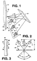
- a projection television receiver 10 is illustrated diagrammatically in FIGURE 1.
- An array 12 of projection cathode ray tubes 14, 16 and 18 provide red, green and blue images respectively.
- the cathode ray tubes are provided with respective lenses 15, 17 and 19.
- the projected images are reflected by a mirror 20 onto a projection screen 22. Additional mirrors can also be utilized, depending on the particular geometry of the optical paths.
- the green cathode ray tube 16 projects the green image along an optical path 32, which has a substantially orthogonal orientation with screen 22. In other words, the optical path is at right angles to the screen.
- the red and blue cathode ray tubes have respective optical paths 34 and 36, which converge toward the first optical path 32 in a non orthogonal orientation defining angles of incidence ⁇ . The angles of incidence introduce the problem of color shift.
- the screen 22 comprises a three dimensional hologram 26 disposed on a substrate 24.
- the screen receives images from the projectors on a first, entrance surface side 28 and displays the images on a second, exit surface side 30, with controlled light dispersion of all the displayed images.
- the substrate is preferably a highly durable, transparent, water-repellent film, such as a polyethylene terephthalate resin film.
- a polyethylene terephthalate resin film is available from E. I. du Pont de Nemours & Co. under the trademark Mylar®.
- the film substrate has a thickness in the range of about 1 - 10 mils, equivalent to about .001 - .01 inches or about 25.4 - 254 microns.
- a film having a thickness of about 7 mils (178 microns) has been found to provide adequate support for the three dimensional hologram disposed thereon.
- the thickness of the film does not affect screen performance in general or color shift performance in particular, and films of different thickness may be utilized.
- the three dimensional hologram 26 has a thickness of not more than approximately 20 microns.
- Three dimensional holographic screens are available from at least two sources. Polaroid Corporation utilizes a proprietary, wet chemical process to form three dimensional holograms in its DMP-128 photo polymer material.
- a preferred embodiment of the three dimensional holographic screens used in the projection television receivers described and claimed herein were manufactured by the Polaroid Corporation wet chemical process, in accordance with the following performance specifications: Horizontal half viewing angle 38° ⁇ 3°, Vertical half viewing angle 10° ⁇ 1°, Screen gain ⁇ 8, Color shift ⁇ 3, where the horizontal and vertical viewing angles are measured conventionally, screen gain is the quotient of light intensity directed from the source toward the rear of the viewing surface, and light intensity from the front of the viewing surface toward the viewer, measured orthogonal to the screen, and color shift is measured as described above.
- FIGURE 2 is a simplified projection television diagram, omitting the mirror and lenses, for explaining color shift performance.
- the optical axes 34 and 36 of the red and blue cathode ray tubes 14 and 18 are aligned symmetrically at angles of incidence ⁇ with respect to the optical axis 32 of the green cathode ray tube 16.
- the minimum depth D of a cabinet is determined by the distance between the screen 22 and the rear edges of the cathode ray tubes. It will be appreciated that as the angle ⁇ becomes smaller, the cathode tubes move closer together, and must be spaced further from the screen to avoid hitting one another. At a sufficiently small angle ⁇ , such interference cannot be avoided. This undesirably increases the minimum depth D of a cabinet. Conversely, as the angle ⁇ gets larger, the cathode ray tubes can be moved closer to the screen 22, reducing the minimum depth D of a cabinet.
- two horizontal half viewing angles are designated - ⁇ and + ⁇ . Together, a total horizontal viewing angle of 2 ⁇ is defined.
- the half viewing angles may typically range from ⁇ 40° to ⁇ 60°. Within each half angle are a plurality of specific angles ⁇ , at which color shift can be measured and determined, in accordance with equations (I) and (II) explained above.
- the color shift of the three dimensional holographic screen is less than or equal to approximately 2 for all the angles of incidence in a first subrange of angles of incidence greater than 0° and less than or equal to approximately 10°; and, the color shift of the screen is less than or equal to approximately 5 for all the angles of incidence in a second subrange of angles of incidence greater than approximately 10° and less than or equal to approximately 30°. It is expected that a color shift of less than or equal to approximately 2, as in the first subrange, can also be achieved in the second subrange of larger angles of incidence.
- the substrate 24 comprises a transparent film, such as Mylar®, as described above.
- the photo polymer material from which the three dimensional hologram 26 is formed is supported on the film layer 24.
- a suitable photo polymer material is DMP-128®.
- the screen 22 may further comprise a light transmissive reinforcing member 38, for example, of an acrylic material, such as polymethylmethacrylate (PMMA). Polycarbonate materials can also be used.
- the reinforcing member 38 is presently a layer having a thickness in the range of approximately 2 - 4 mm.
- the screen 22 and the reinforcing member are adhered to one another throughout the mutual boundary 40 of the holographic layer 26 and the reinforcing member 38. Adhesive, radiation and/or thermal bonding techniques may be utilized.
- the surface 42 of the reinforcing layer may also be treated, for example by one or more of the following: tinting, anti-glare coatings and anti-scratch coatings.
- Various surfaces of the screen and/or its constituent layers may be provided with other optical lenses or lenticular arrays to control aspects of the projection screen bearing on performance characteristics other than color shift performance, as is known to do with conventional projection screens, without impairing the improved color shift performance of the three dimensional holographic projection screen.
Applications Claiming Priority (3)
| Application Number | Priority Date | Filing Date | Title |
|---|---|---|---|
| US08/777,887 US6078351A (en) | 1996-12-31 | 1996-12-31 | Projection televisions with three dimensional holographic screens |
| US777887 | 1996-12-31 | ||
| PCT/US1997/022782 WO1998029776A1 (en) | 1996-12-31 | 1997-12-11 | Projection televisions with three-dimensional holographic screens |
Publications (2)
| Publication Number | Publication Date |
|---|---|
| EP0950210A1 EP0950210A1 (en) | 1999-10-20 |
| EP0950210B1 true EP0950210B1 (en) | 2002-10-16 |
Family
ID=25111605
Family Applications (1)
| Application Number | Title | Priority Date | Filing Date |
|---|---|---|---|
| EP97950929A Expired - Lifetime EP0950210B1 (en) | 1996-12-31 | 1997-12-11 | Projection televisions with three-dimensional holographic screens |
Country Status (8)
| Country | Link |
|---|---|
| US (2) | US6078351A (ko) |
| EP (1) | EP0950210B1 (ko) |
| JP (1) | JP2001507816A (ko) |
| KR (1) | KR100564713B1 (ko) |
| CN (1) | CN1132040C (ko) |
| AU (1) | AU5380598A (ko) |
| DE (1) | DE69716470T2 (ko) |
| WO (1) | WO1998029776A1 (ko) |
Families Citing this family (38)
| Publication number | Priority date | Publication date | Assignee | Title |
|---|---|---|---|---|
| US6078351A (en) * | 1996-12-31 | 2000-06-20 | Thomson Consumer Electronics, Inc. | Projection televisions with three dimensional holographic screens |
| HUP9700348A1 (hu) * | 1997-02-04 | 1998-12-28 | Holografika E.C. | Eljárás és berendezés háromdimenziós kép megjelenítésére |
| US6239830B1 (en) * | 1998-01-21 | 2001-05-29 | New York University | Displayer and method for displaying |
| US6621530B1 (en) * | 1998-01-29 | 2003-09-16 | Thomson Licensing S.A. | Projection televisions with mirrors incident on holographic screens |
| US6483533B1 (en) * | 1998-01-29 | 2002-11-19 | Thomson Licensing S.A. | Projection televisions with three dimensional holographic screens |
| US6400417B1 (en) * | 1998-01-29 | 2002-06-04 | Thomson Licensing S.A. | Projection television with three-dimensional holographic screen and centered blue CRT for balanced CRT drive |
| US6215499B1 (en) * | 1999-05-06 | 2001-04-10 | Phillips Petroleum Company | Method and apparatus for interactive curved surface seismic interpretation and visualization |
| US6665117B2 (en) * | 1999-05-06 | 2003-12-16 | Conocophillips Company | Method and apparatus for interactive curved surface borehole interpretation and visualization |
| US6424464B1 (en) * | 1999-05-06 | 2002-07-23 | Phillips Petroleum Company | Method and apparatus for interactive curved surface seismic interpretation and visualization |
| US20080024598A1 (en) * | 2000-07-21 | 2008-01-31 | New York University | Autostereoscopic display |
| US7102700B1 (en) * | 2000-09-02 | 2006-09-05 | Magic Lantern Llc | Laser projection system |
| KR100442820B1 (ko) * | 2001-05-04 | 2004-08-02 | 삼성전자주식회사 | 큰 입사각을 갖는 홀로그램 기록방법 및 홀로그래픽리플렉터를 이용한 홀로그램 재생장치 및 이를 이용한재생방법 및 홀로그래픽 리플렉터를 이용한평면표시소자장치 |
| US7657097B2 (en) * | 2002-01-24 | 2010-02-02 | Silicon Constellations, Inc. | Picture reproduction system and method utilizing independent picture elements |
| KR20040056415A (ko) * | 2002-12-23 | 2004-07-01 | 삼성전자주식회사 | 프로젝션 텔레비전 |
| KR100516173B1 (ko) * | 2002-12-28 | 2005-09-22 | 삼성전자주식회사 | 곡률 스크린을 구비한 투사형 영상 재생 장치 |
| JP4225816B2 (ja) * | 2003-03-28 | 2009-02-18 | オリンパス株式会社 | 投影光学装置 |
| US20050280894A1 (en) * | 2004-04-02 | 2005-12-22 | David Hartkop | Apparatus for creating a scanning-column backlight in a scanning aperture display device |
| US7573491B2 (en) * | 2004-04-02 | 2009-08-11 | David Hartkop | Method for formatting images for angle-specific viewing in a scanning aperture display device |
| US20050219693A1 (en) * | 2004-04-02 | 2005-10-06 | David Hartkop | Scanning aperture three dimensional display device |
| DE102004016749B4 (de) * | 2004-04-06 | 2007-02-01 | Bauhaus-Universität Weimar | Verfahren und Anordnung zur Überlagerung von texturierten Oberflächen mit digitaler Grafik |
| US9049412B2 (en) * | 2005-03-30 | 2015-06-02 | Tte Technology, Inc. | System and method for projecting video onto a screen |
| EP1889225A4 (en) * | 2005-06-03 | 2012-05-16 | Mediapod | SYSTEM AND METHOD FOR MULTIDIMENSIONAL IMAGING |
| US7281806B2 (en) * | 2005-06-08 | 2007-10-16 | Tte Technology, Inc. | System and method for projecting a video image with a temporal LED combiner |
| CN100422851C (zh) * | 2005-12-23 | 2008-10-01 | 深圳市泛彩溢实业有限公司 | 一种全息投影屏及其制作方法、系统和应用 |
| CN101604096A (zh) * | 2008-06-13 | 2009-12-16 | 深圳Tcl新技术有限公司 | 显示装置及其操作方法 |
| US7911692B2 (en) * | 2009-07-03 | 2011-03-22 | Seiko Epson Corporation | Screen and projection system |
| US8704879B1 (en) | 2010-08-31 | 2014-04-22 | Nintendo Co., Ltd. | Eye tracking enabling 3D viewing on conventional 2D display |
| KR101803571B1 (ko) * | 2011-06-17 | 2017-11-30 | 엘지디스플레이 주식회사 | 입체영상표시장치와 이의 구동방법 |
| US10080049B2 (en) | 2012-09-07 | 2018-09-18 | At&T Intellectual Property I, L.P. | Apparatus and method for presentation of holographic content |
| TWI477883B (zh) * | 2013-01-22 | 2015-03-21 | Hon Hai Prec Ind Co Ltd | 背投電視的光機裝置 |
| WO2014201466A1 (en) | 2013-06-15 | 2014-12-18 | The SuperGroup Creative Omnimedia, Inc. | Method and apparatus for interactive two-way visualization using simultaneously recorded and projected video streams |
| US9402051B2 (en) * | 2013-06-15 | 2016-07-26 | The SuperGroup Creative Omnimedia, Inc. | Apparatus and method for simultaneous live recording through and projecting live video images onto an interactive touch screen |
| CN106292137A (zh) * | 2015-05-11 | 2017-01-04 | 江苏宜清光电科技有限公司 | 一种可以自由定制显示的智能无屏电视 |
| US9819903B2 (en) | 2015-06-05 | 2017-11-14 | The SuperGroup Creative Omnimedia, Inc. | Imaging and display system and method |
| LT3226065T (lt) * | 2016-03-31 | 2023-10-25 | Fisba Ag | Šviesos modulis ir būdas, skirti lazeriniams diodams stebėti šviesos modulyje |
| WO2020036948A1 (en) * | 2018-08-14 | 2020-02-20 | Starport Inc. | Holographic projection system |
| US11927761B1 (en) | 2020-07-21 | 2024-03-12 | Apple Inc. | Head-mounted display systems |
| TW202401126A (zh) * | 2022-05-25 | 2024-01-01 | 日商索尼集團公司 | 圖像顯示裝置 |
Family Cites Families (42)
| Publication number | Priority date | Publication date | Assignee | Title |
|---|---|---|---|---|
| US3625584A (en) * | 1970-01-09 | 1971-12-07 | Holotron Corp | Three dimensional large screen movie techniques employing holography and a cylindrical optical system |
| US4130337A (en) * | 1970-04-21 | 1978-12-19 | Takanori Okoshi | Holographic viewer system |
| US4032968A (en) * | 1974-11-14 | 1977-06-28 | Matsushita Electric Industrial Co., Ltd. | Television image projecting system |
| US4004093A (en) * | 1975-12-12 | 1977-01-18 | Tinsley Laboratories, Inc. | Truncated Schmidt optical systems for projecting color television pictures |
| JPS53115137A (en) * | 1977-03-17 | 1978-10-07 | Sanyo Electric Co Ltd | Projection-type color television device |
| US4520387A (en) * | 1980-08-06 | 1985-05-28 | Moorfeed Corporation | Holographic imager |
| JPS5781254A (en) * | 1980-11-10 | 1982-05-21 | Toshiba Corp | Transmission type projector |
| US4374609A (en) * | 1981-05-21 | 1983-02-22 | Zenith Radio Corporation | Image projection screen with decreased color shift as a function of viewing angle, and method of manufacture |
| US4536056A (en) * | 1981-10-05 | 1985-08-20 | Hitachi, Ltd. | Rear projection apparatus |
| NL8300817A (nl) * | 1983-03-07 | 1984-10-01 | Philips Nv | Projektiescherm. |
| US4556913A (en) * | 1984-01-13 | 1985-12-03 | Rca Corporation | Apparatus for preventing virtual images in projection television receivers |
| JPH0721612B2 (ja) * | 1986-07-25 | 1995-03-08 | 大日本印刷株式会社 | 透過型投影スクリ−ン用レンズシ−ト |
| US4960314A (en) * | 1988-07-05 | 1990-10-02 | Hughes Aircraft Company | Diffraction optics diffusing screen laminate for full color on-axis viewing |
| US5016950A (en) * | 1988-07-05 | 1991-05-21 | Hughes Aircraft Company | Full-color zero-order suppressed diffraction optics diffusing screen/louver filter laminate |
| US5046793A (en) * | 1989-05-26 | 1991-09-10 | Litton Systems, Inc. | Chromatically corrected directional diffusing screen |
| US5241416A (en) * | 1990-05-14 | 1993-08-31 | Canon Kabushiki Kaisha | Screen and projector using said screen |
| CA2044932C (en) * | 1990-06-29 | 1996-03-26 | Masayuki Kato | Display unit |
| JPH04136885A (ja) * | 1990-09-28 | 1992-05-11 | Toppan Printing Co Ltd | リップマン・ホログラムを用いたプロジェクション・テレビ用の反射型スクリーン |
| EP0479490A3 (en) * | 1990-10-02 | 1992-08-12 | Physical Optics Corporation | Volume holographic diffuser |
| EP0484073B1 (en) * | 1990-10-29 | 2000-04-05 | Kuraray Co., Ltd. | Lenticular lens sheet |
| US5349400A (en) * | 1990-11-30 | 1994-09-20 | Thomson-Csf | Back-projection display system and method for making a back-projection mirror |
| JP2911627B2 (ja) * | 1991-03-27 | 1999-06-23 | 株式会社日立製作所 | 大画面投写形ディスプレイ |
| JPH0553195A (ja) * | 1991-08-22 | 1993-03-05 | Fujitsu General Ltd | プロジエクタ装置 |
| US5257130A (en) * | 1992-01-30 | 1993-10-26 | The Walt Disney Company | Apparatus and method for creating a real image illusion |
| JP3388780B2 (ja) * | 1992-06-19 | 2003-03-24 | 株式会社日立製作所 | 背面投写型画像ディスプレイ装置 |
| JP3340766B2 (ja) * | 1992-09-03 | 2002-11-05 | 株式会社リコー | 透過型投射スクリーン |
| WO1995034832A1 (fr) * | 1992-12-15 | 1995-12-21 | Thomson-Csf | Ecran de projection holographique et procede de realisation |
| EP0629899B1 (en) * | 1993-06-14 | 2001-05-23 | Dai Nippon Printing Co., Ltd. | Projection screen |
| WO1995004303A1 (en) * | 1993-07-27 | 1995-02-09 | Physical Optics Corporation | High-brightness directional viewing screen |
| JP2790032B2 (ja) * | 1994-03-11 | 1998-08-27 | 松下電器産業株式会社 | 透過型スクリーンとその製造方法 |
| TW269010B (ko) * | 1994-04-04 | 1996-01-21 | Projectavision Inc | |
| WO1996007953A1 (en) * | 1994-09-06 | 1996-03-14 | Philips Electronics N.V. | Rear projection screen |
| US5576853A (en) * | 1994-12-20 | 1996-11-19 | Polaroid Corporation | Apparatus and methods for making transmission holograms |
| DE69627561T2 (de) * | 1995-02-10 | 2004-03-18 | Sharp K.K. | Projektionsbildanzeigevorrichtung |
| US5760955A (en) * | 1995-04-06 | 1998-06-02 | Philips Electronics North America Corporation | Rear projection screen with reduced speckle |
| JPH08292498A (ja) * | 1995-04-19 | 1996-11-05 | Asahi Glass Co Ltd | 画像表示装置 |
| JPH0973133A (ja) * | 1995-09-05 | 1997-03-18 | Casio Comput Co Ltd | 透過型スクリーン |
| JPH0973132A (ja) * | 1995-09-05 | 1997-03-18 | Casio Comput Co Ltd | 透過型スクリーンおよびこれを用いた表示装置 |
| US6095652A (en) * | 1995-09-15 | 2000-08-01 | Richmond Holographic Research And Development, Ltd. | Projection system |
| JPH09113995A (ja) * | 1995-10-23 | 1997-05-02 | Denso Corp | 表示装置 |
| JP3525584B2 (ja) * | 1995-10-24 | 2004-05-10 | 株式会社デンソー | ホログラム表示装置 |
| US6078351A (en) * | 1996-12-31 | 2000-06-20 | Thomson Consumer Electronics, Inc. | Projection televisions with three dimensional holographic screens |
-
1996
- 1996-12-31 US US08/777,887 patent/US6078351A/en not_active Expired - Fee Related
-
1997
- 1997-12-11 WO PCT/US1997/022782 patent/WO1998029776A1/en active IP Right Grant
- 1997-12-11 JP JP53004198A patent/JP2001507816A/ja not_active Ceased
- 1997-12-11 DE DE69716470T patent/DE69716470T2/de not_active Expired - Fee Related
- 1997-12-11 EP EP97950929A patent/EP0950210B1/en not_active Expired - Lifetime
- 1997-12-11 AU AU53805/98A patent/AU5380598A/en not_active Abandoned
- 1997-12-11 KR KR1019997005977A patent/KR100564713B1/ko not_active IP Right Cessation
- 1997-12-11 CN CN97181121A patent/CN1132040C/zh not_active Expired - Fee Related
-
1998
- 1998-01-29 US US09/341,489 patent/US6639631B1/en not_active Expired - Fee Related
Also Published As
| Publication number | Publication date |
|---|---|
| DE69716470D1 (de) | 2002-11-21 |
| US6639631B1 (en) | 2003-10-28 |
| CN1242083A (zh) | 2000-01-19 |
| JP2001507816A (ja) | 2001-06-12 |
| EP0950210A1 (en) | 1999-10-20 |
| KR100564713B1 (ko) | 2006-03-30 |
| DE69716470T2 (de) | 2003-02-27 |
| WO1998029776A1 (en) | 1998-07-09 |
| AU5380598A (en) | 1998-07-31 |
| KR20000062395A (ko) | 2000-10-25 |
| US6078351A (en) | 2000-06-20 |
| CN1132040C (zh) | 2003-12-24 |
Similar Documents
| Publication | Publication Date | Title |
|---|---|---|
| EP0950210B1 (en) | Projection televisions with three-dimensional holographic screens | |
| US6437914B1 (en) | Projection televisions with holographic screens having center to edge variations | |
| US6483533B1 (en) | Projection televisions with three dimensional holographic screens | |
| EP0995319B1 (en) | Holographic screen projection televisions with optical correction | |
| EP1051859B1 (en) | Direct projection television with three dimensional holographic screen | |
| EP1051856B1 (en) | Projection television with three-dimensional holographic screen and centered blue crt for balanced crt drive | |
| US6400417B1 (en) | Projection television with three-dimensional holographic screen and centered blue CRT for balanced CRT drive | |
| US6621530B1 (en) | Projection televisions with mirrors incident on holographic screens | |
| EP0990348B1 (en) | Projection televisions with three-dimensional holographic screens | |
| EP1051858B1 (en) | Projection television with holographic screen and partly occluded projection lens | |
| EP1051857B1 (en) | Projection televisions with holographic screens having stacked elements | |
| WO1999039514A1 (en) | Projection televisions with mirrors incident on holographic screens | |
| EP1051855A1 (en) | Projection televisions with holographic screens for high off axis exclusion | |
| MXPA99006181A (en) | Projection televisions with three-dimensional holographic screens |
Legal Events
| Date | Code | Title | Description |
|---|---|---|---|
| PUAI | Public reference made under article 153(3) epc to a published international application that has entered the european phase |
Free format text: ORIGINAL CODE: 0009012 |
|
| 17P | Request for examination filed |
Effective date: 19990629 |
|
| AK | Designated contracting states |
Kind code of ref document: A1 Designated state(s): DE FR GB |
|
| 17Q | First examination report despatched |
Effective date: 20000809 |
|
| GRAG | Despatch of communication of intention to grant |
Free format text: ORIGINAL CODE: EPIDOS AGRA |
|
| GRAG | Despatch of communication of intention to grant |
Free format text: ORIGINAL CODE: EPIDOS AGRA |
|
| GRAH | Despatch of communication of intention to grant a patent |
Free format text: ORIGINAL CODE: EPIDOS IGRA |
|
| GRAH | Despatch of communication of intention to grant a patent |
Free format text: ORIGINAL CODE: EPIDOS IGRA |
|
| GRAA | (expected) grant |
Free format text: ORIGINAL CODE: 0009210 |
|
| AK | Designated contracting states |
Kind code of ref document: B1 Designated state(s): DE FR GB |
|
| REG | Reference to a national code |
Ref country code: GB Ref legal event code: FG4D |
|
| REF | Corresponds to: |
Ref document number: 69716470 Country of ref document: DE Date of ref document: 20021121 |
|
| ET | Fr: translation filed | ||
| PLBE | No opposition filed within time limit |
Free format text: ORIGINAL CODE: 0009261 |
|
| STAA | Information on the status of an ep patent application or granted ep patent |
Free format text: STATUS: NO OPPOSITION FILED WITHIN TIME LIMIT |
|
| 26N | No opposition filed |
Effective date: 20030717 |
|
| PGFP | Annual fee paid to national office [announced via postgrant information from national office to epo] |
Ref country code: FR Payment date: 20061214 Year of fee payment: 10 Ref country code: DE Payment date: 20061214 Year of fee payment: 10 |
|
| PGFP | Annual fee paid to national office [announced via postgrant information from national office to epo] |
Ref country code: GB Payment date: 20071128 Year of fee payment: 11 |
|
| PG25 | Lapsed in a contracting state [announced via postgrant information from national office to epo] |
Ref country code: DE Free format text: LAPSE BECAUSE OF NON-PAYMENT OF DUE FEES Effective date: 20080701 |
|
| REG | Reference to a national code |
Ref country code: FR Ref legal event code: ST Effective date: 20081020 |
|
| PG25 | Lapsed in a contracting state [announced via postgrant information from national office to epo] |
Ref country code: FR Free format text: LAPSE BECAUSE OF NON-PAYMENT OF DUE FEES Effective date: 20071231 |
|
| GBPC | Gb: european patent ceased through non-payment of renewal fee |
Effective date: 20081211 |
|
| PG25 | Lapsed in a contracting state [announced via postgrant information from national office to epo] |
Ref country code: GB Free format text: LAPSE BECAUSE OF NON-PAYMENT OF DUE FEES Effective date: 20081211 |