EP0950207B1 - Tv-kamera - Google Patents
Tv-kamera Download PDFInfo
- Publication number
- EP0950207B1 EP0950207B1 EP97954704A EP97954704A EP0950207B1 EP 0950207 B1 EP0950207 B1 EP 0950207B1 EP 97954704 A EP97954704 A EP 97954704A EP 97954704 A EP97954704 A EP 97954704A EP 0950207 B1 EP0950207 B1 EP 0950207B1
- Authority
- EP
- European Patent Office
- Prior art keywords
- camera
- detector
- light source
- laser
- laser light
- Prior art date
- Legal status (The legal status is an assumption and is not a legal conclusion. Google has not performed a legal analysis and makes no representation as to the accuracy of the status listed.)
- Expired - Lifetime
Links
- 238000001514 detection method Methods 0.000 claims description 16
- 239000000835 fiber Substances 0.000 claims description 11
- 230000010354 integration Effects 0.000 claims description 3
- 230000002093 peripheral effect Effects 0.000 claims description 2
- 230000010287 polarization Effects 0.000 claims description 2
- 230000008878 coupling Effects 0.000 description 9
- 238000010168 coupling process Methods 0.000 description 9
- 238000005859 coupling reaction Methods 0.000 description 9
- 230000008901 benefit Effects 0.000 description 7
- 230000003287 optical effect Effects 0.000 description 7
- 238000013461 design Methods 0.000 description 3
- 238000007689 inspection Methods 0.000 description 3
- 230000007246 mechanism Effects 0.000 description 3
- 239000013307 optical fiber Substances 0.000 description 3
- 238000002360 preparation method Methods 0.000 description 3
- 238000005516 engineering process Methods 0.000 description 2
- 230000005284 excitation Effects 0.000 description 2
- 239000004065 semiconductor Substances 0.000 description 2
- 230000006978 adaptation Effects 0.000 description 1
- 230000005540 biological transmission Effects 0.000 description 1
- 238000004624 confocal microscopy Methods 0.000 description 1
- 238000010276 construction Methods 0.000 description 1
- 238000011161 development Methods 0.000 description 1
- 230000018109 developmental process Effects 0.000 description 1
- 238000003384 imaging method Methods 0.000 description 1
- 238000009434 installation Methods 0.000 description 1
- 238000013507 mapping Methods 0.000 description 1
- 238000005259 measurement Methods 0.000 description 1
- 238000000034 method Methods 0.000 description 1
- 238000000386 microscopy Methods 0.000 description 1
- 230000008569 process Effects 0.000 description 1
- 230000001681 protective effect Effects 0.000 description 1
- 238000003908 quality control method Methods 0.000 description 1
- 238000011144 upstream manufacturing Methods 0.000 description 1
Images

Classifications
-
- G—PHYSICS
- G02—OPTICS
- G02B—OPTICAL ELEMENTS, SYSTEMS OR APPARATUS
- G02B21/00—Microscopes
- G02B21/36—Microscopes arranged for photographic purposes or projection purposes or digital imaging or video purposes including associated control and data processing arrangements
-
- G—PHYSICS
- G02—OPTICS
- G02B—OPTICAL ELEMENTS, SYSTEMS OR APPARATUS
- G02B21/00—Microscopes
- G02B21/0004—Microscopes specially adapted for specific applications
- G02B21/002—Scanning microscopes
- G02B21/0024—Confocal scanning microscopes (CSOMs) or confocal "macroscopes"; Accessories which are not restricted to use with CSOMs, e.g. sample holders
Definitions
- the invention relates to a TV camera for microscopic or macroscopic Illustrations.
- TV cameras have been in many different forms for many years Years known from practice. For example, TV cameras are turned on Microscopes are used and are used for image transmission or image acquisition into a mass storage.
- the present invention is based on the object of a TV camera To design microscopic and macroscopic images in this way and to further develop that confocal properties with the smallest possible design can be used that no complex and complicated handling confocal systems with the simple ones in question here Applications are required.
- the microscope is supposed to have a TV camera with confocal Properties are made available to help them cope easier to use tasks wherever the use of existing ones confocal systems are too expensive and their handling is too complex. All over where a quick and easy use, for example biomedical inspection tasks or in the industrial field is desirable; Such a TV camera should be used.
- the user benefits from the confocal Characteristic in particular that even with simpler preparations and thicker cuts very good images are possible, especially Images of those undisturbed by the preparation or the cut Neighboring areas.
- the TV camera according to the invention for microscopic or macroscopic is solved by the characteristics of the images Claim 1.
- the confocal Microscopy known advantages for easy handling in a TV camera let unite, namely, that the confocal system on the Functionality of a TV camera is reduced.
- the - confocal - TV camera a confocal optics, with a simple Laser light source, a scanner, a detector and control electronics, the camera preferably having a monolithic structure inside of the camera body is shaped. This will split into a few precisely adjusted modules made, namely in modules relating to the Excitation or light source, the detector and the scanner.
- the single ones Components can be glued into the housing of the camera.
- the laser light source comprises at least one diode laser the diode laser is a compact light source. expensive Coupling mechanisms are here anyway due to the integrated compact Light source not required.
- Diode laser combination is provided, namely both for on and Multi-color fluorescence as well as for reflection. This also results in a overall compact light source, so that no expensive ones Coupling mechanisms required to couple an external light source are.
- the individual diode lasers are via an alignment coupler with a beam expander Can be coupled into an xy scanner via pinhole optics, here from whole It is particularly important that the laser light source is adjustable overall is arranged. An adjustment of the detector to be discussed later or Detector blocks or upstream pinholes are therefore not required.
- the laser light source can furthermore be fixed filters optimized for the laser be subordinate, depending on the specific application. Also in this respect, the camera is easy to operate.
- the TV camera in further advantageously - especially for universal use - one additional fiber input for coupling a preferably large one external laser over optical fibers, this external laser could preferably serve for transmitted light detection.
- this external laser could preferably serve for transmitted light detection.
- an additional input for a direct coupling of a further lasers may be provided, specifically for the coupling of one not External laser that can be coupled into the fibers. This is also possible through the second additional entrance kept open, which makes the universal Usability of the TV camera increased again.
- the internal lasers have a laser power of more than 1 mW, special protective measures are advantageous and may be necessary. So far the eyepiece is assigned a shutter that protects the Serving operators. Furthermore, there is an automatic Laser shutdown when closing the flap, causing the Security increased again.
- the scanner used in the camera is in the sense of a Point beam scanning mechanism is formed, which is specifically an xy scanner, in particular an xy PHI scanner.
- the picture can be rotated.
- This can be done mechanically rotatable camera adapter can be provided, for example for connection to a microscope.
- the image can be rotated mechanically or rotate, which corresponds to an extremely simple construction.
- the scanner has a scan lens and a optical arrangement for image rotation is subordinate. It is also possible that the scanner comprises an integral arrangement for image rotation. At this Optical arrangement for image rotation can be prisms act in various configurations.
- the arrangement for Image rotation can be designed as a mirror arrangement, for example as a "K" mirror.
- the mirrors used in the mirror arrangement can be a planar Have mirror surface.
- the mirrors with a mirror surface designed as a concave mirror for example for mapping onto a pinhole.
- the scanning optics or the eyepiece to adapt to different microscopes Manufacturer is interchangeable.
- the camera can be used on any Connect microscope system from different manufacturers, creating a high Guaranteed level of compatibility with microscopes from different manufacturers is.
- the detector is a multicolor detector for reflection or fluorescence is trained.
- the detector can also be a spectrometer or a multiband detector.
- the detector is part of a very particularly advantageous embodiment designed as a 3-color detector block with photomultipliers and color filters, whereby it can be a monolithic detector block.
- This Detector block is fixed in the camera housing.
- a detection pinhole could in turn be fixed in the detection beam path be installed, the adjustment of the detection beam in particular advantageously by aligning the laser light source and not by Alignment of the pinhole and / or the detector block takes place. To that extent is a cost-effective and, above all, easy to adjust within the Camera guaranteed.
- Polarization applications may be provided, preferably with color or intensity-coded pole direction. This constructive measure also increased the universal applicability of the camera claimed here.
- the scanner could have a lens with a focusing device macroscopic imaging.
- the TV camera can also be used in the macroscopic area, so for example in quality control in semiconductor technology, especially wherever in the macroscopic area a simple and fast Handling of such a camera is required.
- the scanner could Immediately subordinate a microscope optics and preferably to the Camera housing must be installed. To that extent, a portable one Confocal microscope, consisting of the TV camera and the microscope optics, realize. The universality of the TV camera is again favored.
- control electronics it is also with regard to the universal Usability useful if this is a microprocessor with a Frame buffer and a standard TV output - BAS- includes.
- control electronics could include a scan converter that the converts relatively slow polyfocal scan into standard TV signals, for example in BAS, FBAS, VGA, SVGA, etc. signals. This measure is used to connect standard output devices and standard storage devices, with a special interface for connection such peripheral devices is provided. It can be a act conventional computer interface.
- An external monitor could now be provided for the TV camera a special interface of the TV camera is connected. It would be the same however possible in a particularly advantageous manner in the camera housing to provide an integral display, which is preferably an LCD display is. In this respect, an external monitor would not be necessary.
- the display could in turn include a date and time display, which can be saved together with the image data.
- the Display can be assigned a touchscreen, which makes it a special simple operation of the camera within the touchscreen results.
- the TV camera can be switched on and off.
- the "Intensity” function refers to the control of the laser light source.
- the “Integration” function can be used in particular for weak signals in the The fluorescence process adds up several images and thereby amplifies them. This is particularly special for weakly fluorescent objects Advantage. More controls are in the simplest form in any case not required for the claimed TV camera.
- a digital mass storage device can be arranged in real time, whereby it is can be a magnetic tape or an optical mass storage device. Ultimately, this can be done using a magnetic tape Use conventional tapes, which are advantageous here Tapes can act in a preferably digital video standard.
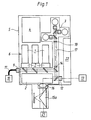
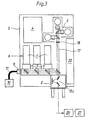
- Embodiments of a TV camera according to the invention show three slightly different from each other Embodiments of a TV camera according to the invention both for microscopic as well as macroscopic images, with the TV camera basically confocal optics with a laser light source 1, a scanner 2, a detector 3 and control electronics 4 comprises.
- the “inner life” of the TV camera is due to a monolithic structure coined within the camera body 5, with a split into a few modules with precise adjustment relating to the excitation or light source 1, the detector 3 and the scanner 2 is realized.
- the laser light source 1 comprises a total of a diode laser combination 6 for one and one Multi-color fluorescence and reflection, this diode laser combination 6 an adjustment coupler 7 with beam expander is arranged downstream. Via pinhole optics 8, the laser light is coupled into the xy scanner 2.
- FIG. 1 to 3 further show that an additional fiber input 9 to Coupling a preferably large external laser 10 over a Optical fiber bundle 11 is provided.
- An exemplary embodiment is additionally an input 12 for direct coupling of a further external laser 13 that cannot be coupled in with fibers.
- Fig. 1 it is indicated that the scanner 2 has a scanning lens 14 and Optical arrangement 15 is arranged for image rotation, which is in the optical arrangement 15, called image rotator for short, around a so-called "K" mirror deals with planar mirror surfaces.
- scanner 2 is one optical arrangement 15 incorporated for image rotation or assigned directly. This is also a variant of a "K" mirror, the Execution as a prism is easily possible.
- FIGS. 1 to 3 An overall view of FIGS. 1 to 3 indicates this.
- the detector 3 is in all three exemplary embodiments according to FIGS. 1 to 3 designed as a multi-color detector for reflection or fluorescence. Regarding further design options of the detector 3 is used to avoid Repetitions refer to the general part of the description, whereby specifically a 3-color detector block with photomultipliers and color filters.
- the figures further show that in the detection beam path 17th a detection pinhole 18 is permanently installed. Adjustment of the detector 3 or Detection pinholes 18 are not provided due to the rigid installation. A Rather, adjustment is done by aligning the laser light source 1.
- FIG. 2 also indicates that the scanner 2 has a lens 19 is subordinate, which is a focusing device for macroscopic May have facility. Within the scope of such a configuration, point the camera directly at an object 20 or in the case of the scanner Connect 2 downstream scan lens 14 to a microscope 21.
- the control electronics 4 includes one not shown in the figures Microprocessor with a frame buffer and a standard TV output. In this regard, is also to avoid repetitions on the general part of the description.
- a display 22 is integrated into the camera housing 5, whereby it is here specifically about an LCD display with the smallest possible space requirement is.
Landscapes
- Physics & Mathematics (AREA)
- Chemical & Material Sciences (AREA)
- Analytical Chemistry (AREA)
- General Physics & Mathematics (AREA)
- Optics & Photonics (AREA)
- Engineering & Computer Science (AREA)
- Multimedia (AREA)
- Microscoopes, Condenser (AREA)
- Color Television Image Signal Generators (AREA)
- Investigating Or Analysing Materials By Optical Means (AREA)
- Studio Devices (AREA)
- Eye Examination Apparatus (AREA)
Description
- Fig. 1
- in einer schematischen Seitenansicht ein erstes Ausführungsbeispiel einer erfindungsgemäßen TV-Kamera, wobei dort lediglich die wesentlichen Merkmale der TV-Kamera dargestellt sind,
- Fig. 2
- in einer schematischen Seitenansicht ein zweites Ausführungsbeispiel einer erfindungsgemäßen TV-Kamera und
- Fig. 3
- in einer schematischen Seitenansicht ein drittes Ausführungsbeispiel einer erfindungsgemäßen TV-Kamera.
- 1
- Laserlichtquelle
- 2
- Scanner
- 3
- Detektor
- 4
- Steuerelektronik
- 5
- Kameragehäuse
- 6
- Diodenlaserkombination
- 7
- Justierkoppler
- 8
- Pinholeoptik
- 9
- Fasereingang
- 10
- Externer Laser (für den Fasereingang)
- 11
- Lichtleitfaser
- 12
- Eingang (für Direktkopplung)
- 13
- Externer Laser (für den Eingang 12)
- 14
- Scanlinse
- 15
- Optische Anordnung zur Bildrotation
- 16
- Scanoptik
- 17
- Detektionsstrahlengang
- 18
- Detektionspinhole
- 19
- Objektiv
- 20
- Objekt
- 21
- Mikroskop
- 22
- Display
Claims (24)
- TV-Kamera zur Durchführung mikroskopischer oder makroskopischer Abbildungen, mit einem Detektor (3), einer Steuerelektronik (4), einer konfokalen Optik, einer Laserlichtquelle (1) und einem Scanner (2) als Komponenten, gekennzeichnet durch ein tragbares Gehäuse (5), in dem die Komponenten angeordnet sind, wodurch die Vorrichtung als Handgerät universell einsetzbar ist.
- Kamera nach Anspruch 1, gekennzeichnet durch einen monolitischen Aufbau innerhalb eines Kameragehäuses (5), mit einer Aufspaltung in wenige justiergenaue Module betreffend die Anregung bzw. Lichtquelle (1), den Detektor (3) und den Scanner (2).
- Kamera nach Anspruch 1 oder 2, dadurch gekennzeichnet, daß die Optik insgesamt polyfokal arbeitet.
- Kamera nach einem der Ansprüche 1 bis 3, dadurch gekennzeichnet, daß die Laserlichtquelle (1) mindestens einen Diodenlaser umfaßt.
- Kamera nach einem der Ansprüche 1 bis 3, dadurch gekennzeichnet, daß als Laserlichtquelle (1) eine Diodenlaserkombination (6) zur Ein- und Mehrfarbfluoreszenz und Reflexion vorgesehen ist.
- Kamera nach Anspruch 5, dadurch gekennzeichnet, daß die einzelnen Diodenlaser über einen Justierkoppler (7) mit Strahlaufweiter über eine Pinholeoptik (8) in einen xy-Scanner (2) einkoppeln.
- Kamera nach einem der Ansprüche 1 bis 6, dadurch gekennzeichnet, daß der Laserlichtquelle (1) auf den Laser optimierte fixe Filter nachgeordnet sind.
- Kamera nach einem der Ansprüche 1 bis 7, dadurch gekennzeichnet, daß ein zusätzlicher Fasereingang (9) zum Einkoppeln eines vorzugsweise großen externen Lasers (10) über ein Lichtleitfaserbündel (11), vorzugsweise für Durchlichtdetektion, vorgesehen ist.
- Kamera nach einem der Ansprüche 1 bis 8, dadurch gekennzeichnet, daß ein zusätzlicher Eingang (12) für eine Direkteinkopplung eines nicht mit Fasern einkoppelbaren externen Lasers (13) vorgesehen ist.
- Kamera nach einem der Ansprüche 1 bis 9, dadurch gekennzeichnet, daß der Detektor (3) als Mehrfarbdetektor für Reflexion oder Fluoreszenz ausgeführt ist.
- Kamera nach einem der Ansprüche 1 bis 10, dadurch gekennzeichnet, daß der Detektor (3) als Spektrometer ausgeführt ist.
- Kamera nach einem der Ansprüche 1 bis 11, dadurch gekennzeichnet, daß der Detektor (3) als Multibanddetektor ausgeführt ist.
- Kamera nach einem der Ansprüche 1 bis 12, dadurch gekennzeichnet, daß der Detektor (3) als 3-Farb-Detektorblock mit Photomultipliern und Farbfiltern ausgeführt ist.
- Kamera anch einem der Ansprüche 1 bis 13, dadurch gekennzeichnet, daß im Detektionstrahlengang (17) ein Detektionspinhole (18) fest eingebaut ist und daß die Justage durch Ausrichten der Laserlichtquelle (1) erfolgt.
- Kamera nach einem der Ansprüche 1 bis 14, dadurch gekennzeichnet, daß im Detektionsstrahlengang (17) ein elektronischer Zoom angeordnet ist.
- Kamera nach einem der Ansprüche 1 bis 15, dadurch gekennzeichnet, daß im Detektionsstrahlengang (17) ein Polfilter für Polarisationsanwendungen angeordnet ist.
- Kamera nach einem der Ansprüche 1 bis 16, dadurch gekennzeichnet, daß die Steuerelektronik (4) einen Mikroprozessor mit einem Bildzwischenspeicher und einem Standard-TV-Ausgang umfaßt.
- Kamera nach Anspruch 17, dadurch gekennzeichnet, daß die Steuerelektronik (4) einen Scankonverter umfaßt, der den relativ langsamen polyfokalen Scan in Standard-TV-Signale wandelt, beispielsweise in BAS-, FBAS-, VGA-, SVGA-, etc. - Signale.
- Kamera nach Anspruch 17 oder 18, dadurch gekennzeichnet, daß eine Schnittstelle zum Anschluß von Peripheriegeräten, insbesondere von Standard-Ausgabegeräten und Standard-Speichereinrichtungen, vorgesehen ist.
- Kamera nach einem der Ansprüche 1 bis 19, dadurch gekennzeichnet, daß im Kameragehäuse (5) ein integrales Display (22) vorgesehen ist.
- Kamera nach Anspruch 20, dadurch gekennzeichnet, daß das Display (22) als LCD-Display ausgeführt ist.
- Kamera nach Anspruch 20 oder 21, dadurch gekennzeichnet, daß das Display (22) eine Datums- und Uhrzeiteinblendung umfaßt.
- Kamera nach einem der Ansprüche 20 bis 22, dadurch gekennzeichnet, daß das Display (22) ein Touchscreen umfaßt.
- Kamera nach einem der Ansprüche 1 bis 23, dadurch gekennzeichnet, daß insgesamt drei Bedienelemente vorgesehen sind, nämlich Bedienelemente für die Funktionen "Start/Stop", "Intensität" und "Integration".
Applications Claiming Priority (3)
| Application Number | Priority Date | Filing Date | Title |
|---|---|---|---|
| DE19654207A DE19654207A1 (de) | 1996-12-24 | 1996-12-24 | TV-Kamera |
| DE19654207 | 1996-12-24 | ||
| PCT/DE1997/002996 WO1998028905A2 (de) | 1996-12-24 | 1997-12-20 | Tv-kamera für mikroscopische oder makroskopische abbildungen |
Publications (2)
| Publication Number | Publication Date |
|---|---|
| EP0950207A2 EP0950207A2 (de) | 1999-10-20 |
| EP0950207B1 true EP0950207B1 (de) | 2003-03-12 |
Family
ID=7816133
Family Applications (1)
| Application Number | Title | Priority Date | Filing Date |
|---|---|---|---|
| EP97954704A Expired - Lifetime EP0950207B1 (de) | 1996-12-24 | 1997-12-20 | Tv-kamera |
Country Status (5)
| Country | Link |
|---|---|
| US (1) | US6433814B1 (de) |
| EP (1) | EP0950207B1 (de) |
| JP (1) | JP2001506836A (de) |
| DE (2) | DE19654207A1 (de) |
| WO (1) | WO1998028905A2 (de) |
Families Citing this family (7)
| Publication number | Priority date | Publication date | Assignee | Title |
|---|---|---|---|---|
| US5788639A (en) * | 1995-07-13 | 1998-08-04 | Lucid Technologies, Inc. | Confocal imaging through thick dermal tissue |
| DE19654208C2 (de) * | 1996-12-24 | 2001-05-10 | Leica Microsystems | Mikroskop |
| ES2436597T3 (es) | 2003-05-20 | 2014-01-03 | Lucid, Inc. | Microscopio confocal para la formación de imágenes de lugares seleccionados del cuerpo de un paciente |
| WO2005059619A1 (de) * | 2003-12-15 | 2005-06-30 | Leica Microsystems Cms Gmbh | Vorrichtung zur bereitstellung eines laserlichtstrahls |
| US7468796B2 (en) * | 2004-08-06 | 2008-12-23 | Compucyte Corporation | Multiple-color monochromatic light absorption and quantification of light absorption in a stained sample |
| DE102005042890B4 (de) * | 2005-09-09 | 2007-05-31 | Leica Microsystems Cms Gmbh | Konfokalmikroskop und Verfahren zur Detektion mit einem Konfokalmikroskop |
| JP4928836B2 (ja) * | 2006-05-30 | 2012-05-09 | 日本分光株式会社 | 顕微装置 |
Family Cites Families (10)
| Publication number | Priority date | Publication date | Assignee | Title |
|---|---|---|---|---|
| US4827125A (en) * | 1987-04-29 | 1989-05-02 | The United States Of America As Represented By The Secretary Of The Department Of Health And Human Services | Confocal scanning laser microscope having no moving parts |
| US4844617A (en) | 1988-01-20 | 1989-07-04 | Tencor Instruments | Confocal measuring microscope with automatic focusing |
| EP0666487A2 (de) * | 1989-09-22 | 1995-08-09 | Fuji Photo Film Co., Ltd. | Rastermikroskop und Abtastmechanismus für dasselbe |
| FR2682490B1 (fr) * | 1991-10-11 | 1993-12-17 | Oreal | Appareil pour observer in vivo la structure microscopique de la peau ou d'un tissu similaire. |
| JP3081699B2 (ja) * | 1992-02-21 | 2000-08-28 | オリンパス光学工業株式会社 | マクロレンズを備えた顕微鏡 |
| JP3343276B2 (ja) * | 1993-04-15 | 2002-11-11 | 興和株式会社 | レーザー走査型光学顕微鏡 |
| US5587832A (en) | 1993-10-20 | 1996-12-24 | Biophysica Technologies, Inc. | Spatially light modulated confocal microscope and method |
| JP3398464B2 (ja) * | 1994-03-17 | 2003-04-21 | ソニー株式会社 | レーザ顕微鏡 |
| US5866911A (en) * | 1994-07-15 | 1999-02-02 | Baer; Stephen C. | Method and apparatus for improving resolution in scanned optical system |
| JPH08237527A (ja) * | 1995-02-23 | 1996-09-13 | Sony Corp | カメラ一体型ビデオテープレコーダー |
-
1996
- 1996-12-24 DE DE19654207A patent/DE19654207A1/de not_active Withdrawn
-
1997
- 1997-12-20 WO PCT/DE1997/002996 patent/WO1998028905A2/de not_active Ceased
- 1997-12-20 US US09/331,459 patent/US6433814B1/en not_active Expired - Lifetime
- 1997-12-20 EP EP97954704A patent/EP0950207B1/de not_active Expired - Lifetime
- 1997-12-20 DE DE59709530T patent/DE59709530D1/de not_active Expired - Lifetime
- 1997-12-20 JP JP52823898A patent/JP2001506836A/ja not_active Withdrawn
Also Published As
| Publication number | Publication date |
|---|---|
| WO1998028905A2 (de) | 1998-07-02 |
| DE19654207A1 (de) | 1998-06-25 |
| EP0950207A2 (de) | 1999-10-20 |
| JP2001506836A (ja) | 2001-05-22 |
| DE59709530D1 (de) | 2003-04-24 |
| WO1998028905A3 (de) | 1999-03-04 |
| US6433814B1 (en) | 2002-08-13 |
Similar Documents
| Publication | Publication Date | Title |
|---|---|---|
| EP1906225B1 (de) | Miniaturisiertes optisch abbildendes System mit hoher lateraler und axialer Auflösung | |
| EP1714187B1 (de) | Mikroskop mit einer lichtquelle mit mehreren mikrostrukturierten optischen elementen | |
| EP1184701B1 (de) | Beleuchtungseinrichtung | |
| EP2149070B1 (de) | Durchstimmbares akusto-optisches filterelement | |
| DE102008062650A1 (de) | Operationsmikroskop zur Beobachtung einer Infrarot-Fluoreszenz und Verfahren hierzu | |
| DE102009010448B4 (de) | Kameraadapter für ein medizinisch optisches Beobachtungsgerät und Kamera-Adapter-Kombination | |
| DE19733195B4 (de) | Hoch-Kompaktes Laser Scanning Mikroskop mit integriertem Kurzpuls Laser | |
| DE10233074B4 (de) | Optische Vorrichtung zum Vereinigen von Lichtstrahlen und Scanmikroskop | |
| DE4323129C2 (de) | Inverses Mikroskop | |
| DE102009019575A1 (de) | Stereoskopisches optisches Beobachtungsgerät und stereoskopisches optisches Beobachtungssystem | |
| DE102014110606B4 (de) | Mikroskop mit einer Strahlteileranordnung | |
| EP0734539B1 (de) | Vorrichtung zum einkoppeln des lichtstrahls eines uv-lasers in ein laser-scanmikroskop | |
| EP0950207A2 (de) | Tv-kamera | |
| DE10044636A1 (de) | Optische Anordnung zur Beleuchtung von Objekten für konfokale Rastermikroskope | |
| WO2010003506A1 (de) | Beleuchtungsanordnung für die tirf-mikroskopie | |
| DE10321091B4 (de) | Mikroskop und Mikroskopierverfahren zur Erzeugung von Überlagerungsbildern | |
| DE102004030669A1 (de) | Mikroskop | |
| EP1168031A2 (de) | Mikroskop-Aufbau | |
| DE10031458B4 (de) | Scan-Mikroskop mit einem Zirkulator | |
| DE4446185C2 (de) | Vorrichtung zum Einkoppeln eines UV-Laserstrahls in ein konfokales Laser-Scanmikroskop | |
| DE102018110795A1 (de) | Mikroskop mit Smartdevice | |
| DE102006045839B4 (de) | Laserscanningmikroskop mit Element zur Pupillenmanipulation | |
| DE10135321B4 (de) | Mikroskop und Verfahren zur Untersuchung einer Probe mit einem Mikroskop | |
| DE102006017350B4 (de) | Abbildungsvorrichtung zum Abbilden mikroskopischer oder makroskopischer Objekte | |
| DE10035688B4 (de) | Optische Anordnung |
Legal Events
| Date | Code | Title | Description |
|---|---|---|---|
| PUAI | Public reference made under article 153(3) epc to a published international application that has entered the european phase |
Free format text: ORIGINAL CODE: 0009012 |
|
| 17P | Request for examination filed |
Effective date: 19990624 |
|
| AK | Designated contracting states |
Kind code of ref document: A2 Designated state(s): CH DE FR GB LI SE |
|
| 17Q | First examination report despatched |
Effective date: 19991221 |
|
| GRAH | Despatch of communication of intention to grant a patent |
Free format text: ORIGINAL CODE: EPIDOS IGRA |
|
| GRAH | Despatch of communication of intention to grant a patent |
Free format text: ORIGINAL CODE: EPIDOS IGRA |
|
| GRAA | (expected) grant |
Free format text: ORIGINAL CODE: 0009210 |
|
| RIN1 | Information on inventor provided before grant (corrected) |
Inventor name: HOPPE, MARTIN Inventor name: ENGELHARDT, JOHANN |
|
| AK | Designated contracting states |
Designated state(s): CH DE FR GB LI SE |
|
| REG | Reference to a national code |
Ref country code: GB Ref legal event code: FG4D Free format text: NOT ENGLISH |
|
| REG | Reference to a national code |
Ref country code: CH Ref legal event code: EP |
|
| REF | Corresponds to: |
Ref document number: 59709530 Country of ref document: DE Date of ref document: 20030424 Kind code of ref document: P |
|
| GBT | Gb: translation of ep patent filed (gb section 77(6)(a)/1977) |
Effective date: 20030506 |
|
| PG25 | Lapsed in a contracting state [announced via postgrant information from national office to epo] |
Ref country code: SE Free format text: LAPSE BECAUSE OF FAILURE TO SUBMIT A TRANSLATION OF THE DESCRIPTION OR TO PAY THE FEE WITHIN THE PRESCRIBED TIME-LIMIT Effective date: 20030612 |
|
| ET | Fr: translation filed | ||
| PG25 | Lapsed in a contracting state [announced via postgrant information from national office to epo] |
Ref country code: LI Free format text: LAPSE BECAUSE OF NON-PAYMENT OF DUE FEES Effective date: 20031231 Ref country code: CH Free format text: LAPSE BECAUSE OF NON-PAYMENT OF DUE FEES Effective date: 20031231 |
|
| PLBE | No opposition filed within time limit |
Free format text: ORIGINAL CODE: 0009261 |
|
| STAA | Information on the status of an ep patent application or granted ep patent |
Free format text: STATUS: NO OPPOSITION FILED WITHIN TIME LIMIT |
|
| 26N | No opposition filed |
Effective date: 20031215 |
|
| REG | Reference to a national code |
Ref country code: CH Ref legal event code: PL |
|
| PGFP | Annual fee paid to national office [announced via postgrant information from national office to epo] |
Ref country code: DE Payment date: 20141211 Year of fee payment: 18 Ref country code: GB Payment date: 20141219 Year of fee payment: 18 |
|
| PGFP | Annual fee paid to national office [announced via postgrant information from national office to epo] |
Ref country code: FR Payment date: 20141219 Year of fee payment: 18 |
|
| REG | Reference to a national code |
Ref country code: DE Ref legal event code: R119 Ref document number: 59709530 Country of ref document: DE |
|
| GBPC | Gb: european patent ceased through non-payment of renewal fee |
Effective date: 20151220 |
|
| REG | Reference to a national code |
Ref country code: FR Ref legal event code: ST Effective date: 20160831 |
|
| PG25 | Lapsed in a contracting state [announced via postgrant information from national office to epo] |
Ref country code: DE Free format text: LAPSE BECAUSE OF NON-PAYMENT OF DUE FEES Effective date: 20160701 Ref country code: GB Free format text: LAPSE BECAUSE OF NON-PAYMENT OF DUE FEES Effective date: 20151220 |
|
| PG25 | Lapsed in a contracting state [announced via postgrant information from national office to epo] |
Ref country code: FR Free format text: LAPSE BECAUSE OF NON-PAYMENT OF DUE FEES Effective date: 20151231 |