EP0950152B1 - Scheibenbremsaufbau - Google Patents
Scheibenbremsaufbau Download PDFInfo
- Publication number
- EP0950152B1 EP0950152B1 EP97951053A EP97951053A EP0950152B1 EP 0950152 B1 EP0950152 B1 EP 0950152B1 EP 97951053 A EP97951053 A EP 97951053A EP 97951053 A EP97951053 A EP 97951053A EP 0950152 B1 EP0950152 B1 EP 0950152B1
- Authority
- EP
- European Patent Office
- Prior art keywords
- disk
- brake shoe
- brake
- rotor disk
- housing
- Prior art date
- Legal status (The legal status is an assumption and is not a legal conclusion. Google has not performed a legal analysis and makes no representation as to the accuracy of the status listed.)
- Expired - Lifetime
Links
- 238000005096 rolling process Methods 0.000 claims description 40
- 239000012530 fluid Substances 0.000 claims description 12
- 239000012528 membrane Substances 0.000 claims description 8
- 230000013011 mating Effects 0.000 claims description 4
- 239000000463 material Substances 0.000 claims description 3
- 230000000452 restraining effect Effects 0.000 claims description 3
- 230000006835 compression Effects 0.000 claims 1
- 238000007906 compression Methods 0.000 claims 1
- 230000003247 decreasing effect Effects 0.000 claims 1
- 239000013013 elastic material Substances 0.000 claims 1
- 238000007789 sealing Methods 0.000 claims 1
- 230000002093 peripheral effect Effects 0.000 description 4
- 238000013016 damping Methods 0.000 description 3
- 238000006073 displacement reaction Methods 0.000 description 3
- 230000006872 improvement Effects 0.000 description 3
- 230000000717 retained effect Effects 0.000 description 3
- 238000010276 construction Methods 0.000 description 2
- 230000008878 coupling Effects 0.000 description 2
- 238000010168 coupling process Methods 0.000 description 2
- 238000005859 coupling reaction Methods 0.000 description 2
- 230000004044 response Effects 0.000 description 2
- 241000239290 Araneae Species 0.000 description 1
- 230000000295 complement effect Effects 0.000 description 1
- 230000006866 deterioration Effects 0.000 description 1
- 239000000428 dust Substances 0.000 description 1
- 238000005516 engineering process Methods 0.000 description 1
- 239000000446 fuel Substances 0.000 description 1
- 230000007257 malfunction Effects 0.000 description 1
- 230000004048 modification Effects 0.000 description 1
- 238000012986 modification Methods 0.000 description 1
- 230000002787 reinforcement Effects 0.000 description 1
- 230000003068 static effect Effects 0.000 description 1
- 239000000725 suspension Substances 0.000 description 1
- 238000009423 ventilation Methods 0.000 description 1
Images


Classifications
-
- F—MECHANICAL ENGINEERING; LIGHTING; HEATING; WEAPONS; BLASTING
- F16—ENGINEERING ELEMENTS AND UNITS; GENERAL MEASURES FOR PRODUCING AND MAINTAINING EFFECTIVE FUNCTIONING OF MACHINES OR INSTALLATIONS; THERMAL INSULATION IN GENERAL
- F16D—COUPLINGS FOR TRANSMITTING ROTATION; CLUTCHES; BRAKES
- F16D65/00—Parts or details
- F16D65/02—Braking members; Mounting thereof
- F16D65/12—Discs; Drums for disc brakes
-
- F—MECHANICAL ENGINEERING; LIGHTING; HEATING; WEAPONS; BLASTING
- F16—ENGINEERING ELEMENTS AND UNITS; GENERAL MEASURES FOR PRODUCING AND MAINTAINING EFFECTIVE FUNCTIONING OF MACHINES OR INSTALLATIONS; THERMAL INSULATION IN GENERAL
- F16D—COUPLINGS FOR TRANSMITTING ROTATION; CLUTCHES; BRAKES
- F16D55/00—Brakes with substantially-radial braking surfaces pressed together in axial direction, e.g. disc brakes
- F16D55/24—Brakes with substantially-radial braking surfaces pressed together in axial direction, e.g. disc brakes with a plurality of axially-movable discs, lamellae, or pads, pressed from one side towards an axially-located member
- F16D55/26—Brakes with substantially-radial braking surfaces pressed together in axial direction, e.g. disc brakes with a plurality of axially-movable discs, lamellae, or pads, pressed from one side towards an axially-located member without self-tightening action
- F16D55/28—Brakes with only one rotating disc
- F16D55/32—Brakes with only one rotating disc actuated by a fluid-pressure device arranged in or on the brake
- F16D55/34—Brakes with only one rotating disc actuated by a fluid-pressure device arranged in or on the brake comprising an expansible fluid-filled flexible member coaxial with the brake
-
- F—MECHANICAL ENGINEERING; LIGHTING; HEATING; WEAPONS; BLASTING
- F16—ENGINEERING ELEMENTS AND UNITS; GENERAL MEASURES FOR PRODUCING AND MAINTAINING EFFECTIVE FUNCTIONING OF MACHINES OR INSTALLATIONS; THERMAL INSULATION IN GENERAL
- F16D—COUPLINGS FOR TRANSMITTING ROTATION; CLUTCHES; BRAKES
- F16D65/00—Parts or details
- F16D65/0006—Noise or vibration control
-
- F—MECHANICAL ENGINEERING; LIGHTING; HEATING; WEAPONS; BLASTING
- F16—ENGINEERING ELEMENTS AND UNITS; GENERAL MEASURES FOR PRODUCING AND MAINTAINING EFFECTIVE FUNCTIONING OF MACHINES OR INSTALLATIONS; THERMAL INSULATION IN GENERAL
- F16D—COUPLINGS FOR TRANSMITTING ROTATION; CLUTCHES; BRAKES
- F16D65/00—Parts or details
- F16D65/02—Braking members; Mounting thereof
- F16D65/12—Discs; Drums for disc brakes
- F16D65/123—Discs; Drums for disc brakes comprising an annular disc secured to a hub member; Discs characterised by means for mounting
-
- F—MECHANICAL ENGINEERING; LIGHTING; HEATING; WEAPONS; BLASTING
- F16—ENGINEERING ELEMENTS AND UNITS; GENERAL MEASURES FOR PRODUCING AND MAINTAINING EFFECTIVE FUNCTIONING OF MACHINES OR INSTALLATIONS; THERMAL INSULATION IN GENERAL
- F16D—COUPLINGS FOR TRANSMITTING ROTATION; CLUTCHES; BRAKES
- F16D65/00—Parts or details
- F16D65/02—Braking members; Mounting thereof
- F16D65/12—Discs; Drums for disc brakes
- F16D65/128—Discs; Drums for disc brakes characterised by means for cooling
-
- F—MECHANICAL ENGINEERING; LIGHTING; HEATING; WEAPONS; BLASTING
- F16—ENGINEERING ELEMENTS AND UNITS; GENERAL MEASURES FOR PRODUCING AND MAINTAINING EFFECTIVE FUNCTIONING OF MACHINES OR INSTALLATIONS; THERMAL INSULATION IN GENERAL
- F16D—COUPLINGS FOR TRANSMITTING ROTATION; CLUTCHES; BRAKES
- F16D65/00—Parts or details
- F16D65/14—Actuating mechanisms for brakes; Means for initiating operation at a predetermined position
- F16D65/16—Actuating mechanisms for brakes; Means for initiating operation at a predetermined position arranged in or on the brake
- F16D65/18—Actuating mechanisms for brakes; Means for initiating operation at a predetermined position arranged in or on the brake adapted for drawing members together, e.g. for disc brakes
- F16D65/186—Actuating mechanisms for brakes; Means for initiating operation at a predetermined position arranged in or on the brake adapted for drawing members together, e.g. for disc brakes with full-face force-applying member, e.g. annular
-
- F—MECHANICAL ENGINEERING; LIGHTING; HEATING; WEAPONS; BLASTING
- F16—ENGINEERING ELEMENTS AND UNITS; GENERAL MEASURES FOR PRODUCING AND MAINTAINING EFFECTIVE FUNCTIONING OF MACHINES OR INSTALLATIONS; THERMAL INSULATION IN GENERAL
- F16D—COUPLINGS FOR TRANSMITTING ROTATION; CLUTCHES; BRAKES
- F16D55/00—Brakes with substantially-radial braking surfaces pressed together in axial direction, e.g. disc brakes
- F16D2055/0004—Parts or details of disc brakes
- F16D2055/005—Brakes straddling an annular brake disc radially internally
-
- F—MECHANICAL ENGINEERING; LIGHTING; HEATING; WEAPONS; BLASTING
- F16—ENGINEERING ELEMENTS AND UNITS; GENERAL MEASURES FOR PRODUCING AND MAINTAINING EFFECTIVE FUNCTIONING OF MACHINES OR INSTALLATIONS; THERMAL INSULATION IN GENERAL
- F16D—COUPLINGS FOR TRANSMITTING ROTATION; CLUTCHES; BRAKES
- F16D55/00—Brakes with substantially-radial braking surfaces pressed together in axial direction, e.g. disc brakes
- F16D2055/0004—Parts or details of disc brakes
- F16D2055/0058—Fully lined, i.e. braking surface extending over the entire disc circumference
-
- F—MECHANICAL ENGINEERING; LIGHTING; HEATING; WEAPONS; BLASTING
- F16—ENGINEERING ELEMENTS AND UNITS; GENERAL MEASURES FOR PRODUCING AND MAINTAINING EFFECTIVE FUNCTIONING OF MACHINES OR INSTALLATIONS; THERMAL INSULATION IN GENERAL
- F16D—COUPLINGS FOR TRANSMITTING ROTATION; CLUTCHES; BRAKES
- F16D65/00—Parts or details
- F16D65/02—Braking members; Mounting thereof
- F16D2065/13—Parts or details of discs or drums
- F16D2065/1304—Structure
- F16D2065/1316—Structure radially segmented
-
- F—MECHANICAL ENGINEERING; LIGHTING; HEATING; WEAPONS; BLASTING
- F16—ENGINEERING ELEMENTS AND UNITS; GENERAL MEASURES FOR PRODUCING AND MAINTAINING EFFECTIVE FUNCTIONING OF MACHINES OR INSTALLATIONS; THERMAL INSULATION IN GENERAL
- F16D—COUPLINGS FOR TRANSMITTING ROTATION; CLUTCHES; BRAKES
- F16D65/00—Parts or details
- F16D65/02—Braking members; Mounting thereof
- F16D2065/13—Parts or details of discs or drums
- F16D2065/1304—Structure
- F16D2065/1328—Structure internal cavities, e.g. cooling channels
-
- F—MECHANICAL ENGINEERING; LIGHTING; HEATING; WEAPONS; BLASTING
- F16—ENGINEERING ELEMENTS AND UNITS; GENERAL MEASURES FOR PRODUCING AND MAINTAINING EFFECTIVE FUNCTIONING OF MACHINES OR INSTALLATIONS; THERMAL INSULATION IN GENERAL
- F16D—COUPLINGS FOR TRANSMITTING ROTATION; CLUTCHES; BRAKES
- F16D65/00—Parts or details
- F16D65/02—Braking members; Mounting thereof
- F16D2065/13—Parts or details of discs or drums
- F16D2065/1304—Structure
- F16D2065/1332—Structure external ribs, e.g. for cooling or reinforcement
-
- F—MECHANICAL ENGINEERING; LIGHTING; HEATING; WEAPONS; BLASTING
- F16—ENGINEERING ELEMENTS AND UNITS; GENERAL MEASURES FOR PRODUCING AND MAINTAINING EFFECTIVE FUNCTIONING OF MACHINES OR INSTALLATIONS; THERMAL INSULATION IN GENERAL
- F16D—COUPLINGS FOR TRANSMITTING ROTATION; CLUTCHES; BRAKES
- F16D65/00—Parts or details
- F16D65/02—Braking members; Mounting thereof
- F16D2065/13—Parts or details of discs or drums
- F16D2065/134—Connection
- F16D2065/1348—Connection resilient
-
- F—MECHANICAL ENGINEERING; LIGHTING; HEATING; WEAPONS; BLASTING
- F16—ENGINEERING ELEMENTS AND UNITS; GENERAL MEASURES FOR PRODUCING AND MAINTAINING EFFECTIVE FUNCTIONING OF MACHINES OR INSTALLATIONS; THERMAL INSULATION IN GENERAL
- F16D—COUPLINGS FOR TRANSMITTING ROTATION; CLUTCHES; BRAKES
- F16D65/00—Parts or details
- F16D65/02—Braking members; Mounting thereof
- F16D2065/13—Parts or details of discs or drums
- F16D2065/134—Connection
- F16D2065/1356—Connection interlocking
- F16D2065/1368—Connection interlocking with relative movement both radially and axially
-
- F—MECHANICAL ENGINEERING; LIGHTING; HEATING; WEAPONS; BLASTING
- F16—ENGINEERING ELEMENTS AND UNITS; GENERAL MEASURES FOR PRODUCING AND MAINTAINING EFFECTIVE FUNCTIONING OF MACHINES OR INSTALLATIONS; THERMAL INSULATION IN GENERAL
- F16D—COUPLINGS FOR TRANSMITTING ROTATION; CLUTCHES; BRAKES
- F16D65/00—Parts or details
- F16D65/02—Braking members; Mounting thereof
- F16D2065/13—Parts or details of discs or drums
- F16D2065/134—Connection
- F16D2065/1384—Connection to wheel hub
-
- F—MECHANICAL ENGINEERING; LIGHTING; HEATING; WEAPONS; BLASTING
- F16—ENGINEERING ELEMENTS AND UNITS; GENERAL MEASURES FOR PRODUCING AND MAINTAINING EFFECTIVE FUNCTIONING OF MACHINES OR INSTALLATIONS; THERMAL INSULATION IN GENERAL
- F16D—COUPLINGS FOR TRANSMITTING ROTATION; CLUTCHES; BRAKES
- F16D65/00—Parts or details
- F16D65/02—Braking members; Mounting thereof
- F16D2065/13—Parts or details of discs or drums
- F16D2065/134—Connection
- F16D2065/1392—Connection elements
- F16D2065/1396—Ancillary resilient elements, e.g. anti-rattle or retraction springs
-
- F—MECHANICAL ENGINEERING; LIGHTING; HEATING; WEAPONS; BLASTING
- F16—ENGINEERING ELEMENTS AND UNITS; GENERAL MEASURES FOR PRODUCING AND MAINTAINING EFFECTIVE FUNCTIONING OF MACHINES OR INSTALLATIONS; THERMAL INSULATION IN GENERAL
- F16D—COUPLINGS FOR TRANSMITTING ROTATION; CLUTCHES; BRAKES
- F16D2121/00—Type of actuator operation force
- F16D2121/02—Fluid pressure
-
- F—MECHANICAL ENGINEERING; LIGHTING; HEATING; WEAPONS; BLASTING
- F16—ENGINEERING ELEMENTS AND UNITS; GENERAL MEASURES FOR PRODUCING AND MAINTAINING EFFECTIVE FUNCTIONING OF MACHINES OR INSTALLATIONS; THERMAL INSULATION IN GENERAL
- F16D—COUPLINGS FOR TRANSMITTING ROTATION; CLUTCHES; BRAKES
- F16D2125/00—Components of actuators
- F16D2125/02—Fluid-pressure mechanisms
- F16D2125/14—Fluid-filled flexible members, e.g. enclosed air bladders
Definitions
- the present invention relates to disk brakes and more particularly to improvements in large area contact disk brakes for vehicles.
- the disk brake of the present invention is a disk brake of the type described in US 5,330,034 issued July 19, 1994 and US RE 35055 issued Oct. 10, 1995 referring to full annular disk brakes for larger vehicles such as trucks.
- the concept of the full annular disk brake is now proposed for automobiles and light trucks and the present invention relates to a structure of a full annular disk brake for such vehicles.
- vibration response is of considerable importance in the design of brakes that may be subjected to dynamic disturbances. Under certain situations, vibrations may cause large displacements and severe stresses in the brake.
- the velocity of a vibrating system is in general, proportional to its frequency and hence a viscous damping force increases with the frequency of vibration.
- Forces resisting a motion also arise from dry friction along a non-lubricated surface. It is usually assumed to be a force of constant magnitude but opposed to the direction of motion.
- damping forces also arise because of imperfect elasticity or internal friction, called hysteric damping, within the body. The magnitude of such a force is independent of the frequency but is proportional to the amplitude, of vibration or to the displacement.
- a construction in accordance with the present invention comprises a disk brake assembly for a vehicle wheel wherein the wheel includes a hub journaled to an axle on the vehicle, the disk brake assembly comprises a housing mounted to the vehicle and at least an annular rotor disk within the housing and means for mounting the disk to the wheel.
- the rotor disk has at least a first radial planar friction surface and the housing includes a first annular brake shoe provided adjacent the first planar friction surface of the disk and movable axially towards and away from the first friction surface.
- At least a first means is provided for restraining the first brake shoe from rotating with the disk.
- the housing also includes an annular radial wall parallel to the first brake shoe, and an annular fluid expandable bladder extending between the first annular brake shoe and the radial wall, whereby upon expansion of the bladder the first brake shoe moves axially to frictionally engage the friction surface of the disk.
- the disk brake assembly further comprises at least a first elastically deformable means for disengaging the first brake shoe from frictional contact with the rotor disk upon release of the fluid from the expandable bladder using energy stored in said first elastically deformable means due to deformation of said first elastically deformable means.
- the radial disk is provided with a second annular friction surface, parallel to the first and on an opposite side of the rotor disk wherein the first and second friction disks have different radii, and a second annular brake shoe adjacent the second annular friction disk wherein brake squeal will be reduced.
- the means for retaining the first brake shoe includes a brake shoe backing plate having an annular periphery and the housing includes a concentric wall having an internal surface radially adjacent the periphery of the first brake shoe while the inner surface of the concentric wall and the periphery of the first brake shoe have mating interdigital elements which allow axial movement of the first brake shoe relative to the concentric wall but prevents peripheral movement of the first brake shoe relative to the concentric wall of the housing.
- the means for disengaging the first' brake shoe from the first friction surface of the rotor disk is at least one rolling seal provided between axially generated adjacent surfaces of the annular radial wall of the housing and the first brake shoe.
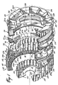
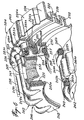
- a disk brake assembly 10 for an automobile having a housing in the form of a shell 12.
- the housing has a cylindrical wall 14 with a corrugated inner surface 16 having valleys 16a and ribs 16b.
- the housing 12 includes a radial annular wall 18 provided with an annular brake pad lining 20.
- the ribs 16b are relatively flat and represent valleys on the outer surface 17 while ribs 17a correspond to valleys 16a.
- the cylindrical wall 14 also includes a radial flange 15.
- the housing 12 also includes an annular radial wall 22 to which is mounted an annular cylindrical corrugated rim 24 adapted to fit within the corrugated inner surface 16 of the wall 14 and is retained therein by flange 15.
- the ribs 24a of the corrugated rim 24 fit in the valleys 16a of surface 16 while the valleys 24b correspond to the ribs 16b of the housing wall 14.
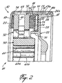
- the radial wall 22 has a hub portion 26 which can be bolted to a flange on an axle (not shown) of the vehicle.
- the radial wall 22 also includes an annular radial planar wall portion 28 and a cylindrical flange 30 as shown in Fig. 2.
- An indented detent 70 is provided in the housing wall 14 in order to lock the housing 12 against axial movement relative to the radial wall 22.
- the detent 70 protrudes inwardly to engage the edge of rim 24.
- An annular rotor disk 32 includes radial planar friction surfaces 34 and 36 and a cylindrical annular rim 38 having an inner corrugated concentric surface 40 with ribs 40a and valleys 40b.
- a hub adapter 42 includes a radial wall portion 44 adapted to be mounted to a vehicle wheel (not shown in the embodiment of Fig. 8) and a cylindrical corrugated wall 46.
- the wall 46 has ribs 46a and valleys 46b which are adapted to fit within the inner surface 40 of the rim 38 of rotor disk 32.
- the rotor disk 32 will be locked against rotational movement relative to the hub adapter 42 but is slidable axially thereon. Since the hub adapter 42 is mounted onto a vehicle wheel the rotor disk 32 will rotate with the wheel.
- the rotor disk 32 is ventilated and therefore has radially extending ventilation passages 48 communicating with openings 49 in housing wall 14. As shown in Figs. 1, 2 and 3, there are axial openings 48a that intersect radial openings 48 so as to ensure that as much air as possible passes through the rotor disk 32.
- a brake shoe 50 includes brake linings 52 and a backing plate 54.
- the brake shoe 50 includes a corrugated peripheral edge 51 engaging the inner surface 16 of the cylindrical wall 14. Thus, the brake shoe 50 can slide axially but is retained against rotational movement relative to the housing 12.
- An annular bladder 56 is provided between the wall 28 and the backing plate 54.
- fluid such as oil
- the bladder 56 When fluid such as oil is fed into the bladder 56 it will expand, moving the brake shoe 50 axially towards the friction surface 36 of rotor disk 32.
- the rotor disk 32 will also slide axially on the hub 42, in response to the force exerted by the bladder 56, and the radial friction surface 34 will come in frictional contact with the brake linings 20.
- the bladder 56 is expanded.
- the oil is allowed to drain from the bladder 56, thereby releasing the axial force on the brake shoe 50, allowing the disk rotor 32 to rotate freely within the housing 12.
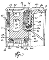
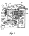
- a pair of rolling seals 62 are located, in the present embodiment, on the outer surface of corrugated wall 46 of the hub adapter 42 and are formed to the contour of the corrugated surface. Pairs of circumferentially extending grooves 46c, 46d are defined in wall 46 to receive the rolling seals 62a and 62b respectively. As shown in Fig. 3, the pair of rolling seals 62a and 62b are pre-compressed when inserted between the hub 42 and the rim 38 of the rotor disk 32. Retainer ring 63 may be provided to hold seal 62a in place.
- Seal 62b is retained by groove 65 formed in wall 46.
- Retainer ring 63 is formed with convexly curved surface 63b to support seal 62a and control the deformation of the seal 62a as will be described.
- the groove 65 is also formed with convexly curved surface 65b to control the deformation of seal 62b.
- the rolling seals 62a, 62b When the brakes are released, the rolling seals 62a, 62b will be restored because of the energy stored therein, and will return to the shape as shown in Fig. 4a, thereby moving the rotor disk 32 and thus drawing the friction surface 34 away from the brake pad 20-
- the rolling seals 62a and 62b can be selected to provide the right amount of clearance to avoid the drag which might occur when the rotor disk 32 remains in contact with the brake pad 20. It is important that only a slight clearance be provided in order to avoid undue pedal movement.
- rolling seal 64 which is located in circumferential groove 30a on the flange 30 engages the flange of backing plate 54 on the brake shoe 50, and will act to return the brake shoe 50 away from the friction surface 36 of the rotor disk 32 when the fluid is drained from the bladder, in order to eliminate drag of the brakes.
- Wiper 66 on the housing 14 seals the brake shoe from debris and dust.
- Fig 5 there is shown a modification to the brakes of the present invention.
- the elements which in Fig. 5 are similar to those in Figs. 1 to 4 have been raised by 100.
- the housing 112 is a shell having a cylindrical wall 114 that now includes a smooth cylindrical wall portion 155 adjacent the corrugated portion 116.
- the radial wall 122 has a smooth cylindrical wall portion 160 adjacent the corrugated peripheral wall 124.
- a ledge 155a is formed between the corrugated wall portion 114 and the smooth wall portion 155 which acts as a stopper for the radial wall 122 having complementary peripheral surfaces, that is between the corrugated wall portion 124 and the smooth wall portion 160. This will eliminate the need for indents 70 as shown in the embodiment of Figs. 1 to 4.
- Fig. 5 The cross-section of Fig. 5 is taken through the radial wall 122 at exactly the position where the bleed openings 170 and 172 for the bladder 156 are located.
- the wall 28 is adapted to receive strain sensor 60.
- strain sensors 60 may be the type known under Trademark MULTIDYN and described in U.S. Patent No. 5,522,270 issued June 4, 1996 to THOMSON-CSF.
- the strain sensor 60 can provide valuable information on the braking efficiencies and the wear of the brake shoes.
- the strain sensor 60 extends somewhat tangentially to the wall 28 and can, therefore, monitor the torque being applied between the hub 26 and the cylindrical flange 30 of radial wall (spider) 22. With the information which can be obtained from strain sensor 60, the temperature of the brakes can be monitored by means of suitable micro processors. For instance, when the brakes are applied, the pressure is known, and if the heat should increase the torque will be reduced-Increased temperature of the brakes will normally signal brake deterioration or malfunction.
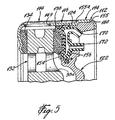
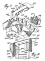
- FIG. 6 to 8 A further embodiment of the present invention is disclosed in Figs. 6 to 8.
- the disk brake 210 is shown mounted to the hub H of a wheel W (Fig. 8).
- the hub adapter 242 is mounted to the hub H by means of bolts.
- the hub adaptor 242 includes a corrugated wall 246 (Figs. 6, 7a and 7b) including ribs 246a and valleys 246b which mate with the corrugated inner surface 240 of rim 238 which is an integral part of the rotor disk 232.
- Fig. 6 illustrates the various elements of this embodiment but without the rotor disk 232.
- the rotor disk 232 is illustrated in Figs, 7a, 7b and 8.
- each rolling seal housing 263 and 265 is made of thin wall stamping and is formed as an annular channel having a lateral width which is greater than the diameter of the rolling seals 262a or 262b respectively.
- the area of the channel is represented by the numeral 263b and 265b in Figs. 7a and 7b.
- the bite portion of the channel forms a ramp which is sloped downwardly from left to right in Figs. 7a and 7b.
- the rolling seals 262a and 262b have stored energy which can overcome the forces applied to the rotor disks 232 by the bladder 256 when the fluid is released from the bladder 256, as will be described.
- the rolling seals 262a and 262b will draw the rotor disk 232 away from the brake pad 220 to a position shown in Fig. 7a.
- the rolling seals 262a and 262b will slide on surface 246 in order to compensate for wear of the brake pad 220.
- the rolling seals 262a and 262b also serve as a suspension to dampen the vibrations between the rotor disk 232 and the hub adaptor 242.
- the housing shell 212 represented by cylindrical wall 214 and radial wall 218 is a thin wall stamping.
- a skirt 218a is formed at the inner edge of the wall 218 to allow the brake pad 220 including a backing wall 221 to be snapped into position within the housing as shown in Figs, 7a and 7b.
- the shell 212 may be assembled from the left end side of Figs. 7a and 7b, with the portion 255 extending over and concentric with the cylindrical wall portion 224 of the radial wall 222.
- a cap 283 which may be hinged in two parts surrounds the enlarged collar portion formed by the extension 255 and has a radial skirt on each edge thereof to form a channel to lock the wall 224 of the radial wall 222 within the housing 212.
- FIG. 6 shows how the two-part cap 283 with short extensions 283a and 283b overlap each other.
- a coupling member 284 extends over the joint so formed by the ends of the hinged cap 283.
- the coupling member 284 includes openings 286 through which pins 288 can pass. These pins are shaped and pass in an area coincident with the valleys in the cap 283.
- the bladder 256 is shown here with a U-shaped membrane 256a having leg portions which are inserted into slots 276 and 278 within the radial wall 222. Reinforcement rings 280 and 282 are also placed in these slots to prevent the membrane 256a from expanding radially.
- the brake shoe 250 including the brake pad 252 and backing plate 254, have a T-shaped configuration with the foot of the T 251 folding back the membrane 256a to form an M, as shown in Figs. 7a and 7b.
- fluid such as oil
- the bladder 256 will expand in the axial direction as shown in Fig. 7b.
- a further ring 230 (corresponding to the flange 30 in Figs. 1 to 4) is also inserted into the groove 278 but extends axially from the radial wall 222 to support a rolling seal 264.
- the backing plate 254 is provided with a channel shaped groove 257 having the same construction as that described with respect to channels 263 and 265 herein.
- the rolling seal 264 which has been somewhat compressed as shown in Fig. 7b, will overcome the reduced axial force, thereby retracting the brake shoe 250 from the friction surface 236 of rotor disk 232. Simultaneously, the rolling seals 262a and 262b will retract the rotor disk 232 from frictional engagement with the brake pad 220.
- a wiper 268 is shown mounted to the backing plate 254 to prevent debris from entering into the rolling seal area 264. Similar wipers (see wiper 66 in Fig. 3) can be provided at other practical locations such as between the backing plate 254 and the cylindrical housing wall 214.
- FIG. 9 and 10 A further improvement to the doove-described embodiment compatible with the invention as claimed in claims 1 to 17 is shown in Figs. 9 and 10.
- the deformable means (rolling seals) are not shown in Figs. 9 and 10.
- the rotor disk 332 has friction surfaces 234 and 236 at different radial distances from the axis of rotation of the rotor disk. As seen in Fig. 10 more clearly, the opposed friction surfaces 334 and 336 are staggered.
- the corresponding brake pads 320 and 352 are also constructed to correspond to the radially staggered friction surfaces 334 and 336.
- the housing wall 314 is accordingly formed in order to accommodate this difference in radius. It has been found, that the amplitude and difference in amplitude of the vibration between pads such as pads 20 and 52 in the embodiment of Figs. 1 through 4 were the major factors contributing to the generation of brake squeal. Brake squeal has been found to be a result of self induced vibration phenomena of the various parts. Under certain situations, vibrations may cause large displacements and severe stresses in the brake. The velocity of a vibrating system is, in general, proportional to its frequency and enhance a viscous stamping force increases with the frequency of vibration.
Landscapes
- Engineering & Computer Science (AREA)
- General Engineering & Computer Science (AREA)
- Mechanical Engineering (AREA)
- Braking Arrangements (AREA)
Claims (17)
- Eine Scheibenbremsvorrichtung (10) für ein Fahrzeug-Rad, wobei das Rad (W) eine mit einer Radachse an dem Fahrzeug verbundene Nabe (H) hat, umfassend ein an dem Fahrzeug montiertes Gehäuse (12, 112, 212) und innerhalb des Gehäuses mindestens eine ringförmige Rotorscheibe (32, 132, 232, 332) und Mittel, die die Scheibe an das Rad montieren, wobei die Scheibe mindestens eine erste radiale, ebene, ringförmige Reibungsoberfläche (36, 136, 236, 336; 34, 134, 234, 334) hat und das Gehäuse mindestens einen ersten ringförmigen, neben der ersten Reibungsoberfläche der Scheibe angeordneten Bremsschuh (50, 150, 250, 350; 20, 120, 220, 320) umfaßt und der Bremsschuh axial auf die erste Reibungsoberfläche hin und davon zurück beweglich ist; mindestens ein erstes Mittel (51, 16, 46a, 46b) zum Verhindern des Mitdrehens des ersten Bremsschuhs mit der Scheibe vorgesehen ist, wobei das Gehäuse eine ringförmige, radiale Wand (22, 122, 222, 322) parallel zum ersten Bremsschuh umfaßt; und einen ringförmigen, durch Flüssigkeit ausdehnbaren Balg (56, 156, 256), der sich zwischen dem ersten ringförmigen Bremsschuh und der radialen Wand erstreckt, wobei sich der Bremsschuh beim Ausdehnen des Balgs axial bewegt und mit der ersten Reibungsoberfläche der Scheibe ineinandergreift; dadurch gekennzeichnet daß die Scheibenbremsvorrichtung weiterhin mindestens ein erstes elastisch verformbares Mittel (64, 264; 62a, 62b, 262a, 262b) zum Entkuppeln des ersten Bremsschuhs vom Reibungskontakt mit der ersten Reibungsoberfläche der Rotorscheibe beim Herauslassen der Flüssigkeit aus dem Balg umfaßt, wobei in dem ersten elastisch verformbaren Mittel (64, 264; 62a, 62b, 262a, 262b) durch Verformung des besagten ersten elastisch verformbaren Mittel gespeicherte Energie verwendet wird.
- Die Scheibenbremsvorrichtung nach Anspruch 1, wobei das Mittel zum Verhindern des Mitdrehens des ersten Bremsschuhs mit der Scheibe eine zylindrische Wand (14, 114), die in dem Gehäuse vorgesehen ist und eine radial an den Umkreis (24) des ersten Bremsschuhs angrenzende, interne Oberfläche (16) hat, und ineinander passende inter-digitale Elemente (16b, 51), die an der internen Oberfläche (16) der konzentrischen Wand (14) und dem Umkreis des ersten Bremsschuhs (50) vorgesehen sind umfaßt, welche inter-digitalen Elemente (16b, 51) eine axiale Bewegung des ersten Bremsschuhs (50, 150) relativ zu der Oberfläche der zylindrischen Wand (14, 114) zulassen aber eine Umkreisbewegung des ersten Bremsschuhs (50) relativ zu der zylindrischen Wand (14) des Gehäuses verhindern.
- Die Scheibenbremsvorrichtung nach Anspruch 2, wobei die inter-digitalen Elemente eine Vielzahl von in Umfangsrichtung beabstandeten, axial herausragenden Rippen (16b) auf der inneren Oberfläche der zylindrischen Wand (14), die mit entsprechenden Tälern (51) auf dem Umkreis des ersten Bremsschuhs (50) ineinander passen.
- Die Scheibenbremsvorrichtung nach einem der vorhergehenden Ansprüche, wobei das Gehäuse (12, 112, 212) weiterhin einen ringförmigen radialen Saum (18, 218a), der durch die zylindrische Wand (14, 214) bedingt und auf der dem ersten Bremsschuh (50, 250) gegenüberliegenden Seite der Rotorscheibe (32, 232) angeordnet ist, umfaßt und ein zweiter Bremsschuh (20, 220), der auf dem ringförmigen Saum (18, 218a) einer zweiten Reibungsoberfläche (34, 234) auf der Rotorscheibe gegenübersteht, vorgesehen ist.
- Die Scheibenbremsvorrichtung nach einem der vorhergehenden Ansprüche, wobei das Mittel zum Entkuppeln des ersten Bremsschuhs (50) von der ersten Reibungsoberfläche (36) der Rotorscheibe (32) mindestens eine Rolldichtung (64) umfaßt, die zwischen einer ringförmig gebildeten Oberfläche des ersten Bremsschuhs (50) und einer ringförmig gebildeten zylindrischen Oberfläche der ersten radialen Wand (22) des Gehäuses, welches sich parallel und benachbart zu der ringförmig gebildeten Oberfläche des ersten Bremsschuhs (50) erstreckt, so daß die Rolldichtung (64) Energie speichern kann, wenn Kraft auf den ersten Bremsschuh ausgeübt wird, um diesen mittels des durch Flüssigkeit ausdehnbaren Balgs (56) reibend auf die erste Reibungsoberfläche (36) der Rotorscheibe einzurücken, und wobei die gespeicherte Energie ausreichend ist, um den ersten Bremsschuh (50) von der ersten Reibungsoberfläche (36) der Rotorscheibe (32) zurückzuziehen, wenn Flüssigkeit aus dem ausdehnbaren Balg herausgelassen wird.
- Die Scheibenbremsvorrichtung nach einem der Ansprüche 4 oder 5, wobei die Mittel, die die Scheibe an das Fahrzeugrad montieren, einen Nabenadapter (42; 242), der zum Mitdrehen mit dem Fahrzeugrad geeignet montierbar ist, umfassen, wobei der Nabenadapter (42; 242) eine zylindrische, äußere Oberfläche (46c, 246) hat; wobei die Rotorscheibe (32, 232) eine durch eine innere zylindrische Wand (40; 240) definierte, zentrale Öffnung umfaßt, und wobei inter-digitale Elemente (46a, 46b; 40a, 40b) auf der äußeren Oberfläche des Nabenadapters (42, 242) und der inneren zylindrischen Oberfläche der Rotorscheibe vorgesehen sind, wodurch besagte inter-digitale Elemente so ineinander passen, daß die Rotorscheibe sich axial auf dem Nabenadapter bewegen kann, aber die Rotorscheibe gegen rotierende Umfangsbewegung relativ zu dem Nabenadapter gehindert wird; und mindestens eine Rolldichtung (62; 262a) zwischen der äußeren zylindrischen Oberfläche (46c; 246c) des Nabenadapters und der inneren zylindrischen Oberfläche (40; 240) der Rotorscheibe (32, 232) platziert und so angeordnet ist, daß, wenn die Rotorscheibe durch die von der Flüssigkeit in dem ausdehnbaren Balg erbracht axiale Kraft axial auf den zweiten Bremsschuh (20;220) hin bewegt wird, die Rolldichtung verformt wird und Energie aufnimmt, so daß, wenn die Flüssigkeit aus dem ausdehnbaren Balg herausgelassen wird, die in der Rolldichtung aufgenommene Energie wirksam wird und die zweite Reibungsoberfläche der Rotorscheibe von dem zweiten Bremsschuh entkuppelt.
- Die Scheibenbremsvorrichtung nach Anspruch 6, wobei es zwei axial beabstandete Rolldichtungen (62a, 62b; 262a, 262b) gibt zwischen der inneren zylindrischen Oberfläche (40; 240) der Rotorscheibe (32; 232) und der äußeren zylindrischen Oberfläche (46c; 246) des Nabenadapters (42; 242).
- Die Scheibenbremsvorrichtung nach Anspruch 6 und 7, wobei die mindestens eine Rolldichtung (62b) in einem auf der äußeren zylindrischen Oberfläche (46) des Nabenadapters (42) geformten Kanal (46d) vorgesehen ist.
- Die Scheibenbremsvorrichtung wie in Anspruch 5 definiert, wobei die ringförmige radiale Wand (22) des Gehäuses einen sich zur Rotorscheibe (32) hin erstreckenden zylindrischen Flansch (30) aufweist und der erste Bremsschuh (50) eine Stützplatte (54) mit einem zylindrischen Wandanteil hat, und eine Rolldichtung (64) in einer Nute (30a) auf dem Flansch (30) montiert ist und mit dem zylindrischen Wandteil der Stützplatte ineinander greift.
- Die Scheibenbremsvorrichtung nach Anspruch 6 oder 7, wobei die Rotorscheibe (232) einen Rand (238), der die innere zylindrische Oberfläche (240) definiert umfaßt, und ein Paar axial beabstandeter Nuten sind in dem Rand (238) vorgesehen und die Rolldichtung aufnehmende Kanäle (263, 265) sind in der Nut auf dem Rand vorgesehen zum Aufnehmen der Rolldichtung (262a, 262b), wobei jeder Kanal einen Eingreifbereich mit einer schiefen Oberfläche, deren Tiefe von einer Seite des Kanals zu der anderen Seite des Kanals abnimmt, hat und wobei die axiale Länge des Kanals (263, 265) größer ist als die axiale Länge der Rolldichtung (262a, 262b), so daß die Rolldichtung zusammengedrückt werden kann, wenn die Rotorscheibe (232) auf den zweiten Bremsschuh hin bewegt wird, und die Rolldichtungen mit der äußeren zylindrischen Oberfläche (246) den Nabenadapters (242) ineinander greifen.
- Die Scheibenbremsvorrichtung nach Anspruch 5, wobei der erste Bremsschuh (232) eine Stützplatte (254) umfaßt, die eine zylindrische Oberfläche gegenüber der radialen, zylindrischen Oberfläche, die von der ersten radialen Wand gebildet wird, bildet; und in der zylindrischen Oberfläche der Stützplatte (254) eine Nute (257) zum Aufnehmen der Rolldichtung (264) definiert ist, wobei die Nute eine radiale Ausdehnung hat, die größer als die radiale Ausdehnung der Rolldichtung ist, und ein Eingreifbereich der Nute eine geneigte Wandanordnung hat, um Kompression auf die Rolldichtung auszuüben, wenn sich der Bremsschuh auf die Rotorscheibe (232) hin bewegt.
- Die Scheibenbremsvorrichtung nach einem der vorhergehenden Ansprüche, wobei der Balg (56, 156) eine axial geschlossene Hülle aus elastischem Material ist und sich zwischen der ersten radialen Wand (22, 122) des Gehäuses (12, 112) und dem ersten Bremsschuh (50, 150) erstreckt.
- Die Scheibenbremsvorrichtung nach einem der Ansprüche 1 bis 11, wobei der Balg (256) eine ausgedehnte ringförmige Membran (256a) aus elastischem flexiblem Material mit parallelen Rändern umfaßt und die Ränder abdichtend mit der ersten radialen Wand (222) des Gehäuses (212) verbunden sind, derart daß der Balg (256) zwischen der Membran (256a) und der ersten radialen Wand (222) gebildet wird.
- Die Scheibenbremsvorrichtung nach Anspruch 13, wobei der erste Bremsschuh (250) eine Stützplatte (254) aufweist mit einem Querschnitt in der Form eines T, wobei das Bein (251) des T sich axial von der Rotorscheibe (232) weg erstreckt, und mit der den Balg bildenden Membran (256a) ineinander greift, so daß der Querschnitt der Membran eine M-Form als Querschnitt hat.
- Die Scheibenbremsvorrichtung nach Anspruch 13 oder 14, wobei die erste radiale Wand (222) des Gehäuses mit einem Paar von radial beabstandeter Umkreis-Spalten versehen ist, und die Enden der Membran (256a) in entsprechenden Spalten zum abdichtenden Verbinden mit der ersten radialen Wand (222) aufgenommen werden.
- Die Scheibenbremsvorrichtung nach einem der vorhergehenden Ansprüche, wobei die Rotorscheibe (332) mindestens eine erste radiale, ringförmige, ebene Reibungsoberfläche (336) mit einem ersten mittleren Radius auf einer Seite und in der Nähe des Umkreises der Scheibe und eine zweite radiale, ringförmige, ebene Reibungsoberfläche (334) auf der anderen Seite der Scheibe parallel zur ersten Reibungsoberfläche, jedoch mit einem mittlerem Radius, der kleiner als der erste mittlere Radius, hat.
- Die Scheibenbremsvorrichtung nach Anspruch 16, wobei das Gehäuse einen ersten Bremsschuh (352), der dazu angepaßt ist, mit der erste Reibungsoberfläche (336) ineinander zu greifen, und einen zweiten Bremsschuh (320), der dazu angepaßt ist, mit einer zweiten Reibungsoberfläche (334) ineinander zu greifen, umfaßt, wobei die versetzten Reibungsoberflächen und Bremsschuhe bewirken, daß die Schwingungen der Bremsvorrichtung gedämpft werden.
Priority Applications (1)
| Application Number | Priority Date | Filing Date | Title |
|---|---|---|---|
| EP03014031A EP1350979A3 (de) | 1996-12-31 | 1997-12-30 | Scheibenbremsanordnung |
Applications Claiming Priority (5)
| Application Number | Priority Date | Filing Date | Title |
|---|---|---|---|
| CA2194206 | 1996-12-31 | ||
| CA 2194206 CA2194206A1 (en) | 1996-12-31 | 1996-12-31 | Disc brake assembly |
| CA 2198537 CA2198537A1 (en) | 1997-02-26 | 1997-02-26 | Improved disc brake assembly |
| CA2198537 | 1997-02-26 | ||
| PCT/CA1997/001014 WO1998029671A1 (en) | 1996-12-31 | 1997-12-30 | Improved disk brake assembly |
Related Child Applications (1)
| Application Number | Title | Priority Date | Filing Date |
|---|---|---|---|
| EP03014031A Division EP1350979A3 (de) | 1996-12-31 | 1997-12-30 | Scheibenbremsanordnung |
Publications (2)
| Publication Number | Publication Date |
|---|---|
| EP0950152A1 EP0950152A1 (de) | 1999-10-20 |
| EP0950152B1 true EP0950152B1 (de) | 2003-08-27 |
Family
ID=25678958
Family Applications (2)
| Application Number | Title | Priority Date | Filing Date |
|---|---|---|---|
| EP97951053A Expired - Lifetime EP0950152B1 (de) | 1996-12-31 | 1997-12-30 | Scheibenbremsaufbau |
| EP03014031A Withdrawn EP1350979A3 (de) | 1996-12-31 | 1997-12-30 | Scheibenbremsanordnung |
Family Applications After (1)
| Application Number | Title | Priority Date | Filing Date |
|---|---|---|---|
| EP03014031A Withdrawn EP1350979A3 (de) | 1996-12-31 | 1997-12-30 | Scheibenbremsanordnung |
Country Status (11)
| Country | Link |
|---|---|
| US (1) | US6328137B1 (de) |
| EP (2) | EP0950152B1 (de) |
| JP (1) | JP2001509236A (de) |
| KR (1) | KR100506556B1 (de) |
| CN (1) | CN1245549A (de) |
| AT (1) | ATE248301T1 (de) |
| AU (1) | AU5474698A (de) |
| BR (1) | BR9714120A (de) |
| DE (1) | DE69724455T2 (de) |
| ES (1) | ES2206764T3 (de) |
| WO (1) | WO1998029671A1 (de) |
Families Citing this family (27)
| Publication number | Priority date | Publication date | Assignee | Title |
|---|---|---|---|---|
| EP0950152B1 (de) * | 1996-12-31 | 2003-08-27 | RANCOURT, Yvon | Scheibenbremsaufbau |
| WO1999041565A1 (fr) * | 1998-02-16 | 1999-08-19 | Multidyn - Newtech | Capteur d'extensiometrie destine a mesurer des deformations a calage mecanique de premiere pose et calibrage automatique en fonction de ce calage |
| FR2788572B1 (fr) | 1999-01-18 | 2001-04-06 | Peugeot Citroen Automobiles Sa | Dispositif de freinage du type frein a disque pour vehicule, comportant un piston annulaire male ou femelle |
| FR2788573B1 (fr) | 1999-01-18 | 2001-04-06 | Peugeot Citroen Automobiles Sa | Dispositif de freinage du type frein a disque pour vehicule automobile, a piston annulaire central |
| FR2788571B1 (fr) | 1999-01-18 | 2001-04-06 | Peugeot Citroen Automobiles Sa | Dispositif de freinage du type frein a disque pour vehicule automobile, comportant un piston annulaire epaule |
| CA2289799A1 (en) | 1999-11-15 | 2001-05-15 | Yvon Rancourt | Improved rotor for disk brake assembly |
| CA2289812A1 (en) | 1999-11-15 | 2001-05-15 | Benoit Raymond | Friction plate return mechanism |
| CA2307753A1 (en) | 2000-05-08 | 2001-11-08 | Groupe Newtech International Inc. | Improved rotor for disc brake assembly |
| CA2314547A1 (en) | 2000-07-25 | 2002-01-25 | Yvon Rancourt | Disc brake housing |
| US6336534B1 (en) | 2000-10-04 | 2002-01-08 | Yvon Rancourt | Flexible brake shoe |
| US6988598B2 (en) * | 2001-11-26 | 2006-01-24 | Mark Williams Enterprises, Inc. | Disc brake rotor mounting system |
| US20040112688A1 (en) * | 2002-02-21 | 2004-06-17 | Yvon Rancourt | Brake wear compensator |
| JP4672490B2 (ja) * | 2005-09-05 | 2011-04-20 | 本田技研工業株式会社 | チェーン駆動の自動二輪車の後輪用ブレーキ装置及びチェーン駆動の自動二輪車の後輪用ブレーキの固定方法 |
| US20070089942A1 (en) * | 2005-09-28 | 2007-04-26 | Baldwin Fred L | Disc brake assembly |
| JP5156325B2 (ja) | 2007-10-11 | 2013-03-06 | カヤバ工業株式会社 | 車両用キャリパブレーキ装置 |
| US20090211856A1 (en) * | 2008-02-22 | 2009-08-27 | Robert Sollenskog | Performance disc brake system |
| EP2581623B1 (de) * | 2010-06-08 | 2021-05-26 | Toyota Jidosha Kabushiki Kaisha | Elektrische bremse für ein fahrzeug |
| CZ22100U1 (cs) | 2010-07-19 | 2011-04-21 | Gebauer@Marek | Axiálne a radiálne chlazený brzdový kotouc s krytem |
| CN102913576A (zh) * | 2011-08-03 | 2013-02-06 | 永克达工业股份有限公司 | 油压刹车器内活塞环结构 |
| JP5613803B2 (ja) * | 2013-08-19 | 2014-10-29 | カヤバ工業株式会社 | キャリパブレーキ装置 |
| US9091313B2 (en) | 2013-08-27 | 2015-07-28 | Akebono Brake Corporation | Full contact brake |
| DE102016010300A1 (de) * | 2016-08-24 | 2018-03-01 | Lucas Automotive Gmbh | Bremsscheibe mit einem Dämpfungselement |
| FR3070191B1 (fr) * | 2017-08-16 | 2020-11-20 | Safran Landing Systems | Procede d'acceleration du refroidissement d'une pile de disques de frein d'aeronef, et dispositif faisant application |
| WO2019099958A1 (en) * | 2017-11-17 | 2019-05-23 | Henderson Wade | Hand truck and pallet system and method of use |
| JP7063195B2 (ja) * | 2018-08-24 | 2022-05-09 | トヨタ自動車株式会社 | 摩擦ブレーキ、車載装置 |
| DE102019107740A1 (de) * | 2019-03-26 | 2020-10-01 | Schaeffler Technologies AG & Co. KG | Elektrische Radantriebseinheit zum Antrieb eines Rades eines Kraftfahrzeuges |
| DE102021213374B4 (de) * | 2021-11-26 | 2023-10-12 | Hl Mando Corporation | Scheibenbremssystem mit einseitiger Druckbeaufschlagung |
Family Cites Families (32)
| Publication number | Priority date | Publication date | Assignee | Title |
|---|---|---|---|---|
| US2256725A (en) * | 1939-06-05 | 1941-09-23 | Gen Motors Corp | Disk brake |
| US2359516A (en) * | 1940-09-18 | 1944-10-03 | Bendix Aviat Corp | Brake |
| US2379972A (en) * | 1944-06-30 | 1945-07-10 | Lambert & Brake Corp | Adapter brake mechanism |
| US2487117A (en) * | 1945-10-05 | 1949-11-08 | Bendix Westinghouse Automotive | Brake mechanism |
| US2453237A (en) * | 1946-08-06 | 1948-11-09 | Letourneau Inc | Multiple-disk friction coupler |
| US2940572A (en) * | 1954-06-28 | 1960-06-14 | Jr Charles P Warman | Fluid clutch actuators |
| US2845146A (en) * | 1955-04-15 | 1958-07-29 | Goodrich Co B F | Expander tube brake structure |
| FR1163308A (fr) * | 1956-12-15 | 1958-09-24 | Batignolles Chatillon | Frein à membrane élastique |
| US2992705A (en) * | 1959-06-12 | 1961-07-18 | Goodyear Tire & Rubber | Brake with deflection compensating pistons |
| US3072220A (en) * | 1960-03-31 | 1963-01-08 | Caterpillar Tractor Co | Disc-type brake with vibration absorbing means |
| US3469658A (en) * | 1968-01-29 | 1969-09-30 | Wichita Clutch Co Inc | Self-aligning,caliper type brake |
| US3885650A (en) * | 1969-12-02 | 1975-05-27 | Hermann Klaue | Spreading disc brake with removable shoes |
| US3830345A (en) * | 1973-04-24 | 1974-08-20 | E Boyles | Disk brakes |
| US3862678A (en) * | 1973-08-02 | 1975-01-28 | Eaton Corp | Cooled coupling with disc stops |
| DE2510640A1 (de) * | 1975-03-12 | 1976-09-23 | Knorr Bremse Gmbh | Bremsscheibe fuer scheibenbremsen von schienenfahrzeugen |
| US4102438A (en) * | 1976-10-18 | 1978-07-25 | The Dolphin Brake Corp. | Disc brake assembly |
| US4562902A (en) * | 1980-05-09 | 1986-01-07 | Clark Equipment Company | Brake system |
| DE3121893A1 (de) * | 1981-06-02 | 1982-12-23 | Alfred Teves Gmbh, 6000 Frankfurt | Teilbelag-schwimmsattelscheibenbremse mit wenigstens einem am bremstraeger befestigten fuehrungsbolzen |
| US4387901A (en) * | 1982-03-08 | 1983-06-14 | The Bendix Corporation | Retraction seal for a disc brake with anti-nibbling feature |
| US4805774A (en) * | 1987-08-27 | 1989-02-21 | Salisbury John W | Support log for shipping sheet material |
| US5238089A (en) * | 1989-12-20 | 1993-08-24 | Akebono Brake Industry Co., Ltd. | Squeak prevention for disc brake |
| US5205380A (en) * | 1990-07-13 | 1993-04-27 | Paquet J Jacques | Disc brake assembly |
| US5076593A (en) * | 1990-11-05 | 1991-12-31 | Itt Corporation | Disc brake caliper seal |
| ATE173527T1 (de) * | 1991-06-20 | 1998-12-15 | Claude Rancourt | Bremsvorrichtung |
| US5330034A (en) * | 1992-03-31 | 1994-07-19 | Claude Rancourt | Brake assembly |
| US5651430A (en) * | 1992-03-31 | 1997-07-29 | Rancourt; Claude | Disc brake assembly |
| KR0174392B1 (ko) * | 1994-03-31 | 1999-02-18 | 토니 헬샴 | 스플라인 |
| US5884388A (en) | 1995-05-12 | 1999-03-23 | Aluminum Company Of America | Method for manufacturing a friction-wear aluminum part |
| US5779006A (en) | 1995-05-24 | 1998-07-14 | The B. F. Goodrich Company | Composite friction disk having replaceable wear faces |
| US5575484A (en) * | 1995-06-30 | 1996-11-19 | Greene, Tweed Of Delaware, Inc. | Fluid pressure activated piston return spring seal |
| EP0950152B1 (de) * | 1996-12-31 | 2003-08-27 | RANCOURT, Yvon | Scheibenbremsaufbau |
| US6029782A (en) * | 1998-03-24 | 2000-02-29 | Dana Corporation | Multiple actuator brake |
-
1997
- 1997-12-30 EP EP97951053A patent/EP0950152B1/de not_active Expired - Lifetime
- 1997-12-30 DE DE69724455T patent/DE69724455T2/de not_active Expired - Fee Related
- 1997-12-30 BR BR9714120-8A patent/BR9714120A/pt not_active Application Discontinuation
- 1997-12-30 AT AT97951053T patent/ATE248301T1/de not_active IP Right Cessation
- 1997-12-30 ES ES97951053T patent/ES2206764T3/es not_active Expired - Lifetime
- 1997-12-30 WO PCT/CA1997/001014 patent/WO1998029671A1/en not_active Ceased
- 1997-12-30 CN CN97181633A patent/CN1245549A/zh active Pending
- 1997-12-30 EP EP03014031A patent/EP1350979A3/de not_active Withdrawn
- 1997-12-30 AU AU54746/98A patent/AU5474698A/en not_active Abandoned
- 1997-12-30 KR KR10-1999-7006009A patent/KR100506556B1/ko not_active Expired - Fee Related
- 1997-12-30 JP JP52951998A patent/JP2001509236A/ja not_active Abandoned
-
1999
- 1999-03-11 US US09/266,028 patent/US6328137B1/en not_active Expired - Fee Related
Also Published As
| Publication number | Publication date |
|---|---|
| CN1245549A (zh) | 2000-02-23 |
| WO1998029671A1 (en) | 1998-07-09 |
| DE69724455D1 (de) | 2003-10-02 |
| EP1350979A3 (de) | 2004-01-07 |
| KR20000069838A (ko) | 2000-11-25 |
| JP2001509236A (ja) | 2001-07-10 |
| US6328137B1 (en) | 2001-12-11 |
| BR9714120A (pt) | 2000-02-29 |
| AU5474698A (en) | 1998-07-31 |
| DE69724455T2 (de) | 2004-06-09 |
| EP1350979A2 (de) | 2003-10-08 |
| EP0950152A1 (de) | 1999-10-20 |
| KR100506556B1 (ko) | 2005-08-05 |
| ES2206764T3 (es) | 2004-05-16 |
| ATE248301T1 (de) | 2003-09-15 |
Similar Documents
| Publication | Publication Date | Title |
|---|---|---|
| EP0950152B1 (de) | Scheibenbremsaufbau | |
| CA1314499C (en) | Dual disk brake | |
| US4537289A (en) | Dust boot for a disc-brake actuating cylinder-and-piston unit | |
| US6443269B1 (en) | Rotor for disc brake assembly | |
| JPS6135790Y2 (de) | ||
| US4671399A (en) | Friction facing assembly | |
| KR19980018982A (ko) | 디스크 브레이크 장치(disc brake device) | |
| US20040026194A1 (en) | Protective boot for a piston-cylinder unit of a disk brake | |
| JPS6141025A (ja) | デイスクブレーキ | |
| US6397982B2 (en) | Disc brake housing | |
| US6135248A (en) | Brake disk | |
| AU775570B2 (en) | Improved disk brake assembly | |
| CA2276514A1 (en) | Improved disk brake assembly | |
| US6622841B2 (en) | Clutch disk | |
| US20040084262A1 (en) | Method and apparatus for brake disc control | |
| MXPA99006182A (en) | Improved disk brake assembly | |
| KR20050086915A (ko) | 자동차용 마찰 디스크 및 자동차용 클러치 | |
| WO2011143149A1 (en) | Sealed floating shim for a brake caliper | |
| JPH0527710Y2 (de) | ||
| CA2198537A1 (en) | Improved disc brake assembly | |
| CA2194206A1 (en) | Disc brake assembly | |
| JPS6155416A (ja) | 車両用ブレ−キ装置 | |
| JPS6155415A (ja) | 車両用ブレ−キ装置 | |
| JP2019183934A (ja) | 車両用ブレーキ装置 | |
| JPS6154971B2 (de) |
Legal Events
| Date | Code | Title | Description |
|---|---|---|---|
| PUAI | Public reference made under article 153(3) epc to a published international application that has entered the european phase |
Free format text: ORIGINAL CODE: 0009012 |
|
| 17P | Request for examination filed |
Effective date: 19990729 |
|
| AK | Designated contracting states |
Kind code of ref document: A1 Designated state(s): AT BE CH DE DK ES FI FR GB GR IE IT LI LU MC NL PT SE |
|
| 17Q | First examination report despatched |
Effective date: 20011120 |
|
| GRAH | Despatch of communication of intention to grant a patent |
Free format text: ORIGINAL CODE: EPIDOS IGRA |
|
| GRAS | Grant fee paid |
Free format text: ORIGINAL CODE: EPIDOSNIGR3 |
|
| GRAA | (expected) grant |
Free format text: ORIGINAL CODE: 0009210 |
|
| AK | Designated contracting states |
Designated state(s): AT BE CH DE DK ES FI FR GB GR IE IT LI LU MC NL PT SE |
|
| PG25 | Lapsed in a contracting state [announced via postgrant information from national office to epo] |
Ref country code: NL Free format text: LAPSE BECAUSE OF FAILURE TO SUBMIT A TRANSLATION OF THE DESCRIPTION OR TO PAY THE FEE WITHIN THE PRESCRIBED TIME-LIMIT Effective date: 20030827 Ref country code: LI Free format text: LAPSE BECAUSE OF FAILURE TO SUBMIT A TRANSLATION OF THE DESCRIPTION OR TO PAY THE FEE WITHIN THE PRESCRIBED TIME-LIMIT Effective date: 20030827 Ref country code: FI Free format text: LAPSE BECAUSE OF FAILURE TO SUBMIT A TRANSLATION OF THE DESCRIPTION OR TO PAY THE FEE WITHIN THE PRESCRIBED TIME-LIMIT Effective date: 20030827 Ref country code: CH Free format text: LAPSE BECAUSE OF FAILURE TO SUBMIT A TRANSLATION OF THE DESCRIPTION OR TO PAY THE FEE WITHIN THE PRESCRIBED TIME-LIMIT Effective date: 20030827 Ref country code: BE Free format text: LAPSE BECAUSE OF FAILURE TO SUBMIT A TRANSLATION OF THE DESCRIPTION OR TO PAY THE FEE WITHIN THE PRESCRIBED TIME-LIMIT Effective date: 20030827 Ref country code: AT Free format text: LAPSE BECAUSE OF FAILURE TO SUBMIT A TRANSLATION OF THE DESCRIPTION OR TO PAY THE FEE WITHIN THE PRESCRIBED TIME-LIMIT Effective date: 20030827 |
|
| REG | Reference to a national code |
Ref country code: GB Ref legal event code: FG4D |
|
| REG | Reference to a national code |
Ref country code: CH Ref legal event code: EP |
|
| REG | Reference to a national code |
Ref country code: IE Ref legal event code: FG4D |
|
| REF | Corresponds to: |
Ref document number: 69724455 Country of ref document: DE Date of ref document: 20031002 Kind code of ref document: P |
|
| PG25 | Lapsed in a contracting state [announced via postgrant information from national office to epo] |
Ref country code: GR Free format text: LAPSE BECAUSE OF FAILURE TO SUBMIT A TRANSLATION OF THE DESCRIPTION OR TO PAY THE FEE WITHIN THE PRESCRIBED TIME-LIMIT Effective date: 20031127 Ref country code: DK Free format text: LAPSE BECAUSE OF FAILURE TO SUBMIT A TRANSLATION OF THE DESCRIPTION OR TO PAY THE FEE WITHIN THE PRESCRIBED TIME-LIMIT Effective date: 20031127 |
|
| REG | Reference to a national code |
Ref country code: SE Ref legal event code: TRGR |
|
| PG25 | Lapsed in a contracting state [announced via postgrant information from national office to epo] |
Ref country code: LU Free format text: LAPSE BECAUSE OF NON-PAYMENT OF DUE FEES Effective date: 20031230 Ref country code: IE Free format text: LAPSE BECAUSE OF NON-PAYMENT OF DUE FEES Effective date: 20031230 |
|
| PG25 | Lapsed in a contracting state [announced via postgrant information from national office to epo] |
Ref country code: MC Free format text: LAPSE BECAUSE OF NON-PAYMENT OF DUE FEES Effective date: 20031231 |
|
| PG25 | Lapsed in a contracting state [announced via postgrant information from national office to epo] |
Ref country code: PT Free format text: LAPSE BECAUSE OF FAILURE TO SUBMIT A TRANSLATION OF THE DESCRIPTION OR TO PAY THE FEE WITHIN THE PRESCRIBED TIME-LIMIT Effective date: 20040127 |
|
| NLV1 | Nl: lapsed or annulled due to failure to fulfill the requirements of art. 29p and 29m of the patents act | ||
| REG | Reference to a national code |
Ref country code: CH Ref legal event code: PL |
|
| REG | Reference to a national code |
Ref country code: ES Ref legal event code: FG2A Ref document number: 2206764 Country of ref document: ES Kind code of ref document: T3 |
|
| ET | Fr: translation filed | ||
| PLBE | No opposition filed within time limit |
Free format text: ORIGINAL CODE: 0009261 |
|
| STAA | Information on the status of an ep patent application or granted ep patent |
Free format text: STATUS: NO OPPOSITION FILED WITHIN TIME LIMIT |
|
| 26N | No opposition filed |
Effective date: 20040528 |
|
| REG | Reference to a national code |
Ref country code: IE Ref legal event code: MM4A |
|
| PGFP | Annual fee paid to national office [announced via postgrant information from national office to epo] |
Ref country code: SE Payment date: 20041229 Year of fee payment: 8 Ref country code: GB Payment date: 20041229 Year of fee payment: 8 Ref country code: FR Payment date: 20041229 Year of fee payment: 8 |
|
| PGFP | Annual fee paid to national office [announced via postgrant information from national office to epo] |
Ref country code: ES Payment date: 20041230 Year of fee payment: 8 Ref country code: DE Payment date: 20041230 Year of fee payment: 8 |
|
| PG25 | Lapsed in a contracting state [announced via postgrant information from national office to epo] |
Ref country code: IT Free format text: LAPSE BECAUSE OF NON-PAYMENT OF DUE FEES Effective date: 20051230 Ref country code: GB Free format text: LAPSE BECAUSE OF NON-PAYMENT OF DUE FEES Effective date: 20051230 |
|
| PG25 | Lapsed in a contracting state [announced via postgrant information from national office to epo] |
Ref country code: SE Free format text: LAPSE BECAUSE OF NON-PAYMENT OF DUE FEES Effective date: 20051231 Ref country code: ES Free format text: LAPSE BECAUSE OF NON-PAYMENT OF DUE FEES Effective date: 20051231 |
|
| PG25 | Lapsed in a contracting state [announced via postgrant information from national office to epo] |
Ref country code: DE Free format text: LAPSE BECAUSE OF NON-PAYMENT OF DUE FEES Effective date: 20060701 |
|
| EUG | Se: european patent has lapsed | ||
| GBPC | Gb: european patent ceased through non-payment of renewal fee |
Effective date: 20051230 |
|
| PG25 | Lapsed in a contracting state [announced via postgrant information from national office to epo] |
Ref country code: FR Free format text: LAPSE BECAUSE OF NON-PAYMENT OF DUE FEES Effective date: 20060831 |
|
| REG | Reference to a national code |
Ref country code: FR Ref legal event code: ST Effective date: 20060831 |
|
| REG | Reference to a national code |
Ref country code: ES Ref legal event code: FD2A Effective date: 20051231 |