EP0949473B2 - Vorrichtung zum schnellen Anfahren einer kryogenischen Luftzerlegungsanlage - Google Patents
Vorrichtung zum schnellen Anfahren einer kryogenischen Luftzerlegungsanlage Download PDFInfo
- Publication number
- EP0949473B2 EP0949473B2 EP99106880A EP99106880A EP0949473B2 EP 0949473 B2 EP0949473 B2 EP 0949473B2 EP 99106880 A EP99106880 A EP 99106880A EP 99106880 A EP99106880 A EP 99106880A EP 0949473 B2 EP0949473 B2 EP 0949473B2
- Authority
- EP
- European Patent Office
- Prior art keywords
- liquid
- column
- distillation column
- collection device
- collected
- Prior art date
- Legal status (The legal status is an assumption and is not a legal conclusion. Google has not performed a legal analysis and makes no representation as to the accuracy of the status listed.)
- Expired - Lifetime
Links
- 238000000926 separation method Methods 0.000 title claims description 55
- 239000007788 liquid Substances 0.000 claims description 145
- 238000004821 distillation Methods 0.000 claims description 47
- 239000000463 material Substances 0.000 claims description 22
- 238000000034 method Methods 0.000 claims description 7
- 238000002156 mixing Methods 0.000 claims description 4
- XKRFYHLGVUSROY-UHFFFAOYSA-N Argon Chemical compound [Ar] XKRFYHLGVUSROY-UHFFFAOYSA-N 0.000 description 116
- 229910052786 argon Inorganic materials 0.000 description 58
- IJGRMHOSHXDMSA-UHFFFAOYSA-N Atomic nitrogen Chemical compound N#N IJGRMHOSHXDMSA-UHFFFAOYSA-N 0.000 description 14
- 239000000047 product Substances 0.000 description 10
- QVGXLLKOCUKJST-UHFFFAOYSA-N atomic oxygen Chemical compound [O] QVGXLLKOCUKJST-UHFFFAOYSA-N 0.000 description 9
- 239000001301 oxygen Substances 0.000 description 9
- 229910052760 oxygen Inorganic materials 0.000 description 9
- 239000000203 mixture Substances 0.000 description 8
- 238000012856 packing Methods 0.000 description 8
- 238000012546 transfer Methods 0.000 description 8
- 229910052757 nitrogen Inorganic materials 0.000 description 7
- MYMOFIZGZYHOMD-UHFFFAOYSA-N Dioxygen Chemical compound O=O MYMOFIZGZYHOMD-UHFFFAOYSA-N 0.000 description 4
- 238000010586 diagram Methods 0.000 description 4
- 239000007789 gas Substances 0.000 description 4
- 238000010992 reflux Methods 0.000 description 3
- 230000000717 retained effect Effects 0.000 description 2
- 238000009825 accumulation Methods 0.000 description 1
- 230000001174 ascending effect Effects 0.000 description 1
- 238000009835 boiling Methods 0.000 description 1
- 238000003889 chemical engineering Methods 0.000 description 1
- 238000009833 condensation Methods 0.000 description 1
- 230000005494 condensation Effects 0.000 description 1
- 230000007423 decrease Effects 0.000 description 1
- 238000013461 design Methods 0.000 description 1
- 230000000694 effects Effects 0.000 description 1
- 230000005484 gravity Effects 0.000 description 1
- 238000012423 maintenance Methods 0.000 description 1
- 238000004519 manufacturing process Methods 0.000 description 1
- QVGXLLKOCUKJST-NJFSPNSNSA-N oxygen-18 atom Chemical compound [18O] QVGXLLKOCUKJST-NJFSPNSNSA-N 0.000 description 1
- 230000003134 recirculating effect Effects 0.000 description 1
- 238000005057 refrigeration Methods 0.000 description 1
- 238000012958 reprocessing Methods 0.000 description 1
- 230000000630 rising effect Effects 0.000 description 1
- 239000013589 supplement Substances 0.000 description 1
- 230000008016 vaporization Effects 0.000 description 1
- 239000002699 waste material Substances 0.000 description 1
Images


Classifications
-
- F—MECHANICAL ENGINEERING; LIGHTING; HEATING; WEAPONS; BLASTING
- F25—REFRIGERATION OR COOLING; COMBINED HEATING AND REFRIGERATION SYSTEMS; HEAT PUMP SYSTEMS; MANUFACTURE OR STORAGE OF ICE; LIQUEFACTION SOLIDIFICATION OF GASES
- F25J—LIQUEFACTION, SOLIDIFICATION OR SEPARATION OF GASES OR GASEOUS OR LIQUEFIED GASEOUS MIXTURES BY PRESSURE AND COLD TREATMENT OR BY BRINGING THEM INTO THE SUPERCRITICAL STATE
- F25J3/00—Processes or apparatus for separating the constituents of gaseous or liquefied gaseous mixtures involving the use of liquefaction or solidification
- F25J3/02—Processes or apparatus for separating the constituents of gaseous or liquefied gaseous mixtures involving the use of liquefaction or solidification by rectification, i.e. by continuous interchange of heat and material between a vapour stream and a liquid stream
- F25J3/04—Processes or apparatus for separating the constituents of gaseous or liquefied gaseous mixtures involving the use of liquefaction or solidification by rectification, i.e. by continuous interchange of heat and material between a vapour stream and a liquid stream for air
- F25J3/04763—Start-up or control of the process; Details of the apparatus used
- F25J3/04866—Construction and layout of air fractionation equipments, e.g. valves, machines
- F25J3/04872—Vertical layout of cold equipments within in the cold box, e.g. columns, heat exchangers etc.
-
- F—MECHANICAL ENGINEERING; LIGHTING; HEATING; WEAPONS; BLASTING
- F25—REFRIGERATION OR COOLING; COMBINED HEATING AND REFRIGERATION SYSTEMS; HEAT PUMP SYSTEMS; MANUFACTURE OR STORAGE OF ICE; LIQUEFACTION SOLIDIFICATION OF GASES
- F25J—LIQUEFACTION, SOLIDIFICATION OR SEPARATION OF GASES OR GASEOUS OR LIQUEFIED GASEOUS MIXTURES BY PRESSURE AND COLD TREATMENT OR BY BRINGING THEM INTO THE SUPERCRITICAL STATE
- F25J3/00—Processes or apparatus for separating the constituents of gaseous or liquefied gaseous mixtures involving the use of liquefaction or solidification
- F25J3/02—Processes or apparatus for separating the constituents of gaseous or liquefied gaseous mixtures involving the use of liquefaction or solidification by rectification, i.e. by continuous interchange of heat and material between a vapour stream and a liquid stream
- F25J3/04—Processes or apparatus for separating the constituents of gaseous or liquefied gaseous mixtures involving the use of liquefaction or solidification by rectification, i.e. by continuous interchange of heat and material between a vapour stream and a liquid stream for air
- F25J3/04406—Processes or apparatus for separating the constituents of gaseous or liquefied gaseous mixtures involving the use of liquefaction or solidification by rectification, i.e. by continuous interchange of heat and material between a vapour stream and a liquid stream for air using a dual pressure main column system
- F25J3/04412—Processes or apparatus for separating the constituents of gaseous or liquefied gaseous mixtures involving the use of liquefaction or solidification by rectification, i.e. by continuous interchange of heat and material between a vapour stream and a liquid stream for air using a dual pressure main column system in a classical double column flowsheet, i.e. with thermal coupling by a main reboiler-condenser in the bottom of low pressure respectively top of high pressure column
-
- F—MECHANICAL ENGINEERING; LIGHTING; HEATING; WEAPONS; BLASTING
- F25—REFRIGERATION OR COOLING; COMBINED HEATING AND REFRIGERATION SYSTEMS; HEAT PUMP SYSTEMS; MANUFACTURE OR STORAGE OF ICE; LIQUEFACTION SOLIDIFICATION OF GASES
- F25J—LIQUEFACTION, SOLIDIFICATION OR SEPARATION OF GASES OR GASEOUS OR LIQUEFIED GASEOUS MIXTURES BY PRESSURE AND COLD TREATMENT OR BY BRINGING THEM INTO THE SUPERCRITICAL STATE
- F25J3/00—Processes or apparatus for separating the constituents of gaseous or liquefied gaseous mixtures involving the use of liquefaction or solidification
- F25J3/02—Processes or apparatus for separating the constituents of gaseous or liquefied gaseous mixtures involving the use of liquefaction or solidification by rectification, i.e. by continuous interchange of heat and material between a vapour stream and a liquid stream
- F25J3/04—Processes or apparatus for separating the constituents of gaseous or liquefied gaseous mixtures involving the use of liquefaction or solidification by rectification, i.e. by continuous interchange of heat and material between a vapour stream and a liquid stream for air
- F25J3/04472—Processes or apparatus for separating the constituents of gaseous or liquefied gaseous mixtures involving the use of liquefaction or solidification by rectification, i.e. by continuous interchange of heat and material between a vapour stream and a liquid stream for air using the cold from cryogenic liquids produced within the air fractionation unit and stored in internal or intermediate storages
- F25J3/04478—Processes or apparatus for separating the constituents of gaseous or liquefied gaseous mixtures involving the use of liquefaction or solidification by rectification, i.e. by continuous interchange of heat and material between a vapour stream and a liquid stream for air using the cold from cryogenic liquids produced within the air fractionation unit and stored in internal or intermediate storages for controlling purposes, e.g. start-up or back-up procedures
-
- F—MECHANICAL ENGINEERING; LIGHTING; HEATING; WEAPONS; BLASTING
- F25—REFRIGERATION OR COOLING; COMBINED HEATING AND REFRIGERATION SYSTEMS; HEAT PUMP SYSTEMS; MANUFACTURE OR STORAGE OF ICE; LIQUEFACTION SOLIDIFICATION OF GASES
- F25J—LIQUEFACTION, SOLIDIFICATION OR SEPARATION OF GASES OR GASEOUS OR LIQUEFIED GASEOUS MIXTURES BY PRESSURE AND COLD TREATMENT OR BY BRINGING THEM INTO THE SUPERCRITICAL STATE
- F25J3/00—Processes or apparatus for separating the constituents of gaseous or liquefied gaseous mixtures involving the use of liquefaction or solidification
- F25J3/02—Processes or apparatus for separating the constituents of gaseous or liquefied gaseous mixtures involving the use of liquefaction or solidification by rectification, i.e. by continuous interchange of heat and material between a vapour stream and a liquid stream
- F25J3/04—Processes or apparatus for separating the constituents of gaseous or liquefied gaseous mixtures involving the use of liquefaction or solidification by rectification, i.e. by continuous interchange of heat and material between a vapour stream and a liquid stream for air
- F25J3/04642—Recovering noble gases from air
- F25J3/04648—Recovering noble gases from air argon
- F25J3/04654—Producing crude argon in a crude argon column
- F25J3/04666—Producing crude argon in a crude argon column as a parallel working rectification column of the low pressure column in a dual pressure main column system
- F25J3/04672—Producing crude argon in a crude argon column as a parallel working rectification column of the low pressure column in a dual pressure main column system having a top condenser
- F25J3/04678—Producing crude argon in a crude argon column as a parallel working rectification column of the low pressure column in a dual pressure main column system having a top condenser cooled by oxygen enriched liquid from high pressure column bottoms
-
- F—MECHANICAL ENGINEERING; LIGHTING; HEATING; WEAPONS; BLASTING
- F25—REFRIGERATION OR COOLING; COMBINED HEATING AND REFRIGERATION SYSTEMS; HEAT PUMP SYSTEMS; MANUFACTURE OR STORAGE OF ICE; LIQUEFACTION SOLIDIFICATION OF GASES
- F25J—LIQUEFACTION, SOLIDIFICATION OR SEPARATION OF GASES OR GASEOUS OR LIQUEFIED GASEOUS MIXTURES BY PRESSURE AND COLD TREATMENT OR BY BRINGING THEM INTO THE SUPERCRITICAL STATE
- F25J3/00—Processes or apparatus for separating the constituents of gaseous or liquefied gaseous mixtures involving the use of liquefaction or solidification
- F25J3/02—Processes or apparatus for separating the constituents of gaseous or liquefied gaseous mixtures involving the use of liquefaction or solidification by rectification, i.e. by continuous interchange of heat and material between a vapour stream and a liquid stream
- F25J3/04—Processes or apparatus for separating the constituents of gaseous or liquefied gaseous mixtures involving the use of liquefaction or solidification by rectification, i.e. by continuous interchange of heat and material between a vapour stream and a liquid stream for air
- F25J3/04642—Recovering noble gases from air
- F25J3/04648—Recovering noble gases from air argon
- F25J3/04654—Producing crude argon in a crude argon column
- F25J3/04666—Producing crude argon in a crude argon column as a parallel working rectification column of the low pressure column in a dual pressure main column system
- F25J3/04672—Producing crude argon in a crude argon column as a parallel working rectification column of the low pressure column in a dual pressure main column system having a top condenser
- F25J3/04703—Producing crude argon in a crude argon column as a parallel working rectification column of the low pressure column in a dual pressure main column system having a top condenser being arranged in more than one vessel
-
- F—MECHANICAL ENGINEERING; LIGHTING; HEATING; WEAPONS; BLASTING
- F25—REFRIGERATION OR COOLING; COMBINED HEATING AND REFRIGERATION SYSTEMS; HEAT PUMP SYSTEMS; MANUFACTURE OR STORAGE OF ICE; LIQUEFACTION SOLIDIFICATION OF GASES
- F25J—LIQUEFACTION, SOLIDIFICATION OR SEPARATION OF GASES OR GASEOUS OR LIQUEFIED GASEOUS MIXTURES BY PRESSURE AND COLD TREATMENT OR BY BRINGING THEM INTO THE SUPERCRITICAL STATE
- F25J3/00—Processes or apparatus for separating the constituents of gaseous or liquefied gaseous mixtures involving the use of liquefaction or solidification
- F25J3/02—Processes or apparatus for separating the constituents of gaseous or liquefied gaseous mixtures involving the use of liquefaction or solidification by rectification, i.e. by continuous interchange of heat and material between a vapour stream and a liquid stream
- F25J3/04—Processes or apparatus for separating the constituents of gaseous or liquefied gaseous mixtures involving the use of liquefaction or solidification by rectification, i.e. by continuous interchange of heat and material between a vapour stream and a liquid stream for air
- F25J3/04763—Start-up or control of the process; Details of the apparatus used
- F25J3/04769—Operation, control and regulation of the process; Instrumentation within the process
- F25J3/04781—Pressure changing devices, e.g. for compression, expansion, liquid pumping
-
- F—MECHANICAL ENGINEERING; LIGHTING; HEATING; WEAPONS; BLASTING
- F25—REFRIGERATION OR COOLING; COMBINED HEATING AND REFRIGERATION SYSTEMS; HEAT PUMP SYSTEMS; MANUFACTURE OR STORAGE OF ICE; LIQUEFACTION SOLIDIFICATION OF GASES
- F25J—LIQUEFACTION, SOLIDIFICATION OR SEPARATION OF GASES OR GASEOUS OR LIQUEFIED GASEOUS MIXTURES BY PRESSURE AND COLD TREATMENT OR BY BRINGING THEM INTO THE SUPERCRITICAL STATE
- F25J3/00—Processes or apparatus for separating the constituents of gaseous or liquefied gaseous mixtures involving the use of liquefaction or solidification
- F25J3/02—Processes or apparatus for separating the constituents of gaseous or liquefied gaseous mixtures involving the use of liquefaction or solidification by rectification, i.e. by continuous interchange of heat and material between a vapour stream and a liquid stream
- F25J3/04—Processes or apparatus for separating the constituents of gaseous or liquefied gaseous mixtures involving the use of liquefaction or solidification by rectification, i.e. by continuous interchange of heat and material between a vapour stream and a liquid stream for air
- F25J3/04763—Start-up or control of the process; Details of the apparatus used
- F25J3/04769—Operation, control and regulation of the process; Instrumentation within the process
- F25J3/04793—Rectification, e.g. columns; Reboiler-condenser
- F25J3/048—Argon recovery
-
- F—MECHANICAL ENGINEERING; LIGHTING; HEATING; WEAPONS; BLASTING
- F25—REFRIGERATION OR COOLING; COMBINED HEATING AND REFRIGERATION SYSTEMS; HEAT PUMP SYSTEMS; MANUFACTURE OR STORAGE OF ICE; LIQUEFACTION SOLIDIFICATION OF GASES
- F25J—LIQUEFACTION, SOLIDIFICATION OR SEPARATION OF GASES OR GASEOUS OR LIQUEFIED GASEOUS MIXTURES BY PRESSURE AND COLD TREATMENT OR BY BRINGING THEM INTO THE SUPERCRITICAL STATE
- F25J3/00—Processes or apparatus for separating the constituents of gaseous or liquefied gaseous mixtures involving the use of liquefaction or solidification
- F25J3/02—Processes or apparatus for separating the constituents of gaseous or liquefied gaseous mixtures involving the use of liquefaction or solidification by rectification, i.e. by continuous interchange of heat and material between a vapour stream and a liquid stream
- F25J3/04—Processes or apparatus for separating the constituents of gaseous or liquefied gaseous mixtures involving the use of liquefaction or solidification by rectification, i.e. by continuous interchange of heat and material between a vapour stream and a liquid stream for air
- F25J3/04763—Start-up or control of the process; Details of the apparatus used
- F25J3/04866—Construction and layout of air fractionation equipments, e.g. valves, machines
- F25J3/04896—Details of columns, e.g. internals, inlet/outlet devices
-
- F—MECHANICAL ENGINEERING; LIGHTING; HEATING; WEAPONS; BLASTING
- F25—REFRIGERATION OR COOLING; COMBINED HEATING AND REFRIGERATION SYSTEMS; HEAT PUMP SYSTEMS; MANUFACTURE OR STORAGE OF ICE; LIQUEFACTION SOLIDIFICATION OF GASES
- F25J—LIQUEFACTION, SOLIDIFICATION OR SEPARATION OF GASES OR GASEOUS OR LIQUEFIED GASEOUS MIXTURES BY PRESSURE AND COLD TREATMENT OR BY BRINGING THEM INTO THE SUPERCRITICAL STATE
- F25J2200/00—Processes or apparatus using separation by rectification
- F25J2200/90—Details relating to column internals, e.g. structured packing, gas or liquid distribution
-
- F—MECHANICAL ENGINEERING; LIGHTING; HEATING; WEAPONS; BLASTING
- F25—REFRIGERATION OR COOLING; COMBINED HEATING AND REFRIGERATION SYSTEMS; HEAT PUMP SYSTEMS; MANUFACTURE OR STORAGE OF ICE; LIQUEFACTION SOLIDIFICATION OF GASES
- F25J—LIQUEFACTION, SOLIDIFICATION OR SEPARATION OF GASES OR GASEOUS OR LIQUEFIED GASEOUS MIXTURES BY PRESSURE AND COLD TREATMENT OR BY BRINGING THEM INTO THE SUPERCRITICAL STATE
- F25J2205/00—Processes or apparatus using other separation and/or other processing means
- F25J2205/02—Processes or apparatus using other separation and/or other processing means using simple phase separation in a vessel or drum
-
- F—MECHANICAL ENGINEERING; LIGHTING; HEATING; WEAPONS; BLASTING
- F25—REFRIGERATION OR COOLING; COMBINED HEATING AND REFRIGERATION SYSTEMS; HEAT PUMP SYSTEMS; MANUFACTURE OR STORAGE OF ICE; LIQUEFACTION SOLIDIFICATION OF GASES
- F25J—LIQUEFACTION, SOLIDIFICATION OR SEPARATION OF GASES OR GASEOUS OR LIQUEFIED GASEOUS MIXTURES BY PRESSURE AND COLD TREATMENT OR BY BRINGING THEM INTO THE SUPERCRITICAL STATE
- F25J2235/00—Processes or apparatus involving steps for increasing the pressure or for conveying of liquid process streams
- F25J2235/04—Processes or apparatus involving steps for increasing the pressure or for conveying of liquid process streams using a pressure accumulator
-
- F—MECHANICAL ENGINEERING; LIGHTING; HEATING; WEAPONS; BLASTING
- F25—REFRIGERATION OR COOLING; COMBINED HEATING AND REFRIGERATION SYSTEMS; HEAT PUMP SYSTEMS; MANUFACTURE OR STORAGE OF ICE; LIQUEFACTION SOLIDIFICATION OF GASES
- F25J—LIQUEFACTION, SOLIDIFICATION OR SEPARATION OF GASES OR GASEOUS OR LIQUEFIED GASEOUS MIXTURES BY PRESSURE AND COLD TREATMENT OR BY BRINGING THEM INTO THE SUPERCRITICAL STATE
- F25J2235/00—Processes or apparatus involving steps for increasing the pressure or for conveying of liquid process streams
- F25J2235/58—Processes or apparatus involving steps for increasing the pressure or for conveying of liquid process streams the fluid being argon or crude argon
-
- F—MECHANICAL ENGINEERING; LIGHTING; HEATING; WEAPONS; BLASTING
- F25—REFRIGERATION OR COOLING; COMBINED HEATING AND REFRIGERATION SYSTEMS; HEAT PUMP SYSTEMS; MANUFACTURE OR STORAGE OF ICE; LIQUEFACTION SOLIDIFICATION OF GASES
- F25J—LIQUEFACTION, SOLIDIFICATION OR SEPARATION OF GASES OR GASEOUS OR LIQUEFIED GASEOUS MIXTURES BY PRESSURE AND COLD TREATMENT OR BY BRINGING THEM INTO THE SUPERCRITICAL STATE
- F25J2245/00—Processes or apparatus involving steps for recycling of process streams
- F25J2245/02—Recycle of a stream in general, e.g. a by-pass stream
-
- F—MECHANICAL ENGINEERING; LIGHTING; HEATING; WEAPONS; BLASTING
- F25—REFRIGERATION OR COOLING; COMBINED HEATING AND REFRIGERATION SYSTEMS; HEAT PUMP SYSTEMS; MANUFACTURE OR STORAGE OF ICE; LIQUEFACTION SOLIDIFICATION OF GASES
- F25J—LIQUEFACTION, SOLIDIFICATION OR SEPARATION OF GASES OR GASEOUS OR LIQUEFIED GASEOUS MIXTURES BY PRESSURE AND COLD TREATMENT OR BY BRINGING THEM INTO THE SUPERCRITICAL STATE
- F25J2290/00—Other details not covered by groups F25J2200/00 - F25J2280/00
- F25J2290/62—Details of storing a fluid in a tank
Definitions
- This invention relates a method and an apparatus for efficiently restarting a distillation column of a cryogenic air separation plant after an interruption in operation, according to the preamble of claims 1 and 3.
- Such a method and apparatus are known from DE 3732363 A1.
- the shutdown or interruption may be caused by a number of reasons such as power interruption, equipment problem, oversupply of non-condensable gas to a column, or an economic choice brought about by high power rates.
- the non-productive period from restart until product purities are re-established is costly, consuming the same amount of power as during normal production, but not providing desired product.
- product may have to be delivered by other means during downtime at considerable cost and burden on a product delivery system. At many plants the number of unscheduled shutdowns or Interruptions in operation makes this non-productive period a significant factor.
- a vertical composition profile exists throughout a distillation column.
- the liquid held up at various levels in the column becomes progressively richer in the more volatile component in ascending order in the column.
- Examples of composition profiles typical of air separation plants may be found in published literature (e.g. R. Latimer, "Distillation of Air", Chemical Engineering Progress, Volume 63, Number 2, pp. 35-59, 1967).
- a distillation column in an air separation plant promotes separation of the components of air when the air, in liquid and vapor form, contacts internal material situated In the distillation column.
- the internal material may be any of the known materials used to promote separation in distillation columns such as trays or packing. Rising vapor in the column serves to hold up liquid on internal material in the column.
- liquid retained at the bottom or sump of the column(s) is normally drained or is reprocessed to re-establish desired purity.
- refrigeration provided by that liquid to the plant is lost, representing a power penalty.
- reprocessing liquid from the sump upon restart, significant time is required to re-establish purity of liquid, resulting In costly power consumption.
- Another aspect of the Invention is:
- the invention accomplishes an efficient restart of an air separation column or columns in a cryogenic air separation plant.
- the efficient re-start is accomplished by collecting descending liquid in a distillation column when operation is interrupted or stopped in that column, and then using the collected liquid to re-inventory the distillation column separation section before or upon re-start.
- Descending liquid refers to liquid that drains or descends from the internal material and inner walls in a distillation column of the plant.
- a distillation column where there is a main condenser, collecting descending liquid in the column prevents mixing of that liquid with accumulated liquid in the bottom of the column, thus preventing loss in purity of the bottom liquid.
- the collected liquid is provided to the separation section of the column, i.e. that section of the column having internal material. In this separation section, collected liquid is used to re-inventory the internal material therein with liquid. Maintenance of the purity of the main condenser and re-inventory of liquid to the separation section each promote a more efficient re-start of the column in a timely manner.
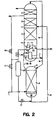
- a collection device situated in a distillation column, is used to divert the flow of descending liquid from a main condenser pool and maintain purity therein.
- the collection device or collector comprises, for example, a sealed tray 10 with risers 11 covered by hats IIA.
- the collector 10 allows vapor and liquid to flow counter-currently without impeding one another.
- Liquid collects on the sealed tray 10 and drains through one or more passages or downcomers 12 that extend below the tray. These downcomers 12 contain a branch.
- One leg 13 of this branch is open to the upper column 4.
- the other leg or diversion circuit 14 is piped to outside of the column.
- Diversion circuit 14 contains a valve 15.
- valve 15 During normal operation of the plant, valve 15 is closed and descending liquid collects on sealed tray 10, flows down the downcomer 12 and overflows through leg 13 to the pool of liquid oxygen 18 below at the main condenser 6. Upon shutdown or interruption in operation, valve 15 is opened and the liquid 19 accumulating on sealed tray 10 flows through downcomer 12 and is diverted through valve 15. Upon resumption of air feed to the plant, valve 15 is closed and operation of the plant continues with the pool of oxygen 18, at the main condenser 6, at essentially the same purity as before operation was interrupted.
- Piping 12, 13 and 14 are schematically shown in Fig. 1 and could be modified according to accepted design practices for cryogenic liquid service. For example, thermal expansion joints could be included and the diversion circuit 14 could be located outside the column 4.
- the system illustrated Fig. 1 requires little capital investment. Because purity of bottom liquid is maintained, this method also decreases the required time for an air separation plant to produce desirable product following a shutdown or interruption in operation.
- the invention is applicable to any air separation cycle.
- the embodiment of the invention shown in Fig. 1 is especially useful for an air separation process producing high purity oxygen product.
- Fig. 1 The system shown in Fig. 1 is effectively a portion of that shown in Fig. 2, which shows a cryogenic air separation plant having two columns.
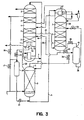
- Fig. 2 discloses now descending liquid in an air separation distillation column is collected and stored in a holding vessel when operation of the column is interrupted. The liquid in the holding vessel is made available to re-inventory the separation section of the same column from which liquid was collected.
- Fig. 2 clean cold air under moderate pressure in piping 1 is fed to high pressure or lower distillation column 2.
- Lower column 2 can employ internal material 3 of any type suitable in its separation section, e. g. trays, or packing normally used in the industry to carry out the separation process.
- the air stream is separated to produce a nitrogen rich stream at the top and a liquid in equilibrium with the feed air, called kettle liquid 23, at the bottom.
- Kettle liquid 23 at the bottom of lower column 2 is transferred to an intermediate level in low pressure or upper distillation column 4 by piping 5.
- Upper column 4 is also fitted with internal material 3 in its separation section, which is not necessarily the same as the internal material of lower column 2.
- Nitrogen 22 taken off at the top of lower column 2 is piped to main condenser 6 where it is totally condensed against vaporizing liquid oxygen 18 at the bottom of upper column 4.
- the resulting liquid nitrogen 7 is divided into two streams, 8 and 9.
- Stream 8 returns a portion of the liquid nitrogen to lower column 2 as reflux.
- the remainder, stream 9, transfers liquid nitrogen as reflux to the top of upper column 4.
- a collection device e.g., a sealed tray 10 collects descending liquid within upper column 4 at a level above main condenser 6.
- This sealed tray 10 prevents descending liquid, such as from internal material 3, from reaching main condenser 6 and contaminating the oxygen liquid pool 18.
- the oxygen concentration or purity of the oxygen liquid pool 18 is typically within the range of from 95-99.9 mole percent.
- valves 15 and 16 are opened. Opening these valves causes liquid flow from collector 10 to be diverted from leg 13 and to flow through diversion circuit 14 to holding vessel 20.
- Holding vessel 20 may be located either inside or outside the cold box that encloses the distillation column 4.
- Holding vessel 20 is sized such that it can hold the contents of the liquid from upper column 4 and, in cases where a conventional three column arrangement is used, the contents of the argon column also.
- the volume of holding vessel 20 is typically 5-20 percent of the volume of the upper and argon columns.
- the size of holding vessel 20 depends on whether the internals are trays or packing. Valve 16 is opened while vessel 20 is filled, to allow pressure equalization between upper column 4 and holding vessel 20.
- liquid inside holding vessel 20 may be used to re-inventory internal material 3 in the separation section of upper column 4.
- Re-inventory of liquid to the upper column can be accomplished by pressure transfer. Valves 15 and 16 are closed and valve 17 opened. By so doing, the pressure in holding vessel 20 is raised to that of lower column 2. The stored liquid is then transferred to upper column 4. This transfer of liquid can be accomplished by metering the liquid into the sump of lower column 2. Liquid in holding vessel 20 then flows through valve 21 into kettle liquid transfer line 5.
- the liquid transfer rate is controlled such that the oxygen purity in main condenser 6 is maintained.
- valves 17 and 21 are closed and valve 16 is opened.
- the pressure in holding vessel 20 is reduced to the pressure of upper column 4.
- the system is then in a stand-by state for the next interruption in operation of the distillation column.
- the return line from holding vessel 20 can enter at any location in the separation section of upper column 4 of Figure 2. It can also be used to inventory the low ratio or argon column condenser 27. Optionally, although not preferred, it could even provide liquid to the argon column 30 itself in three column plants.
- FIG. 3 a three column arrangement is shown with upper and lower distillation columns as in Fig. 2 and a third distillation column where argon is produced.
- liquid in an argon column of an air separation plant is collected upon interruption of the operation of the column.
- the collected liquid may be stored in a holding vessel.
- liquid collected from that column is used to re-inventory the separation section of the argon column which contains internal material 3.
- argon column 30 During normal operation, a crude argon column vapor feed 31 from upper column 4 is passed to argon column 30 and a liquid stream 32 is returned to the upper column 4 at the same location. Liquid inside argon column 30 has a much higher argon concentration than liquid in upper column 4. It is therefore advantageous to keep argon column 30 liquid separated from upper column 4 liquid during shut down or interruption in operation of the argon column.
- argon column liquid can be prevented from mixing with upper column liquid by applying an analogous piping scheme as in the embodiment illustrated in Fig. 2 to the base of argon column 30.
- An external holding vessel 40 can be used for liquid argon storage.
- a vessel sharing the same shell as argon column 30 can be used, but with a separating head. Collected argon column liquid is pumped or pressure transferred via piping 38 back to the top of argon column 30 or to some intermediate location within the separation section of that column.
- valves 33 and 34 are closed.
- Valve 36 is open such that the pressure in holding vessel 40 is the same as the pressure at the base of argon column 30.
- valve 33 is opened and argon rich liquid in argon column 30 is transferred to holding vessel 40 rather than upper column 4.
- valves 33 and 36 are closed. Valve 34 is opened. The pressure in holding vessel 40 is raised to that of lower column 2. Liquid contained in holding vessel 40 is passed back, through control valve 35, to re-inventory a separation section of argon column 30. Optimally, the collected liquid is-provided to an intermediate position within argon column 30.
- superstaged argon distillation columns can be used to produce an argon product with low oxygen concentration, less than 10 ppm oxygen.
- a superstaged argon column contains a greater number of stages than a low ratio argon column. It includes both the number of stages required for the low ratio argon column plus additional stages required for high purity or product grade argon.
- Superstaged columns require a considerable amount of time to achieve product purity following an interruption in operation. This is because superstaged columns have very large numbers of stages, and the liquid held up in the superstaged column is argon which is a minor component of air. Interruption of operation of argon or superstaged argon columns can occur either due to condenser binding or a loss of feed air to the air separation plant. Condenser binding refers to an accumulation of non-condensable vapors, e.g. excessive nitrogen, that will prevent condensation of vapor at the top of the argon column against the refrigerating liquid at the top of the argon column.
- the superstaged column is perhaps the most important of all columns to maintain liquid inventory since it contains a large volume of argon. In normal operation, it takes a period of several hours following start-up to inventory the internal material of the superstaged argon column with a steady state amount of liquid with the correct composition.
- the three column arrangement includes a superstaged argon column 50.
- vapor 31 from the upper column 4 is provided to argon column 50.
- Valve 58 is closed and liquid 51 is returned to upper column 4, via pump 52, through open valve 54 and piping 56.
- descending liquid is collected at the bottom of that column. The liquid level rises in column 50 from LL1 up to LL2.
- valve 58 Upon re-start of the superstaged column, valve 58 is opened. Liquid 51 is transferred from the bottom of column 50 via pump 52 through valve 58 to a dedicated line 60 to column 50 to re-inventory the separation section therein. Usually, liquid re-inventory is started before re-starting gas supply to the column. Providing liquid to the top or an intermediate section of column 50 builds liquid on the internal material 3 in the separation section.
- the composition of collected liquid 51 is equal to the average composition of liquid held-up in column 50 during normal operation.
- vapor 31 is drawn from upper column 4 into the superstaged column 50 and liquid reflux 62 flows from the condenser and supplements the liquid 60 being pumped to the top of column 50.
- the recirculative liquid 60 valve 58 is slowly closed and the liquid 56 upper column valve 54 is slowly opened.
- the recirculation loop valve 58 is eventually fully closed and normal operation is resumed with return liquid 56 to the upper column controlling the sump liquid level.
- the cryogenic air separation plant has a two section argon column that includes a low ratio argon column 50A and an additional column 50B with sufficient stages so that the combination is equivalent to the superstaged argon column 50 illustrated in Fig. 4.
- the split column of Fig. 5 is sometimes desired to meet column height restrictions.
- descending liquid in column 50A can be sent via piping 75 to the bottom of the additional column 50B.
- Efficient re-start of the column(s) is again achieved by recirculating liquid 83 from the bottom of additional column 50B back to the top of the additional column 50B via valve 88 and piping 90, and to the top of column 50A, via valve 74 and piping 76, before or upon drawing vapor into the columns 50A and 50B.
- the invention can be utilized with any process arrangement.
- the holding vessel can be pressurized using a common line between the lower column or the pre-purified air feed from the warm end of the plant.
- the vent line can be sent to the-waste or vented to the atmosphere.
Landscapes
- Engineering & Computer Science (AREA)
- Physics & Mathematics (AREA)
- Mechanical Engineering (AREA)
- Thermal Sciences (AREA)
- General Engineering & Computer Science (AREA)
- Separation By Low-Temperature Treatments (AREA)
Claims (4)
- Verfahren für den effizienten Neustart einer Destillationskolonne (4), bei welcher es sich um die Niederdruckkolonne einer Tieftemperatur-Luftzerlegungsanlage mit Doppelkolonne handelt, nach einer Betriebsunterbrechung, wobei die Kolonne einen Zerlegungsabschnitt (3) und einen Sumpf-Hauptkondensator (6) aufweist und Flüssigkeit enthält, wobei im Zuge des Verfahrens:(A) während einer Betriebsunterbrechung herabströmende Flüssigkeit (19) von dem Zerlegungsabschnitt (3) der Destillationskolonne (4) gesammelt wird;(B) die in Schritt (A) gesammelte Flüssigkeit zu dem Zerlegungsabschnitt (3) der Destillationskolonne (4) an einer Stelle zurückgeleitet wird, die oberhalb der Stelle angeordnet ist, an welcher die herabströmende Flüssigkeit (19) in Schritt (A) gesammelt wurde; und(C) die Destillationskolonne (4) neu gestartet wird;wobei in Schritt (A) die herabströmende Flüssigkeit (19) mittels einer Sammelvorrichtung (10) gesammelt wird, welche während einer Betriebsunterbrechung die herabströmende Flüssigkeit daran hindert, sich mit der im Sumpf der Destillationskolonne (4) angesammelten Flüssigkeit (18) zu mischen, wobei die in Schritt (A) gesammelte Flüssigkeit (19) zu einem Haltebehälter (20) geleitet wird, um getrennt von dem Sumpf der Destillationskolonne (4) gespeichert zu werden, und anschließend in den Zerlegungsabschnitt (3) der Destillationskolonne (4) zurückgeleitet wird, und wobei die Sammelvorrichtung (10) zwischen dem Sumpf-Hauptkondensator (6) und dem Zerlegungsabschnitt (3) der Destillationskolonne angeordnet ist;
wobei
die Sammelvorrichtung (10) mit mindestens einer Leitung (12) verbunden ist, die sich von der Sammelvorrichtung (10) nach unten erstreckt und eine Verzweigung mit einem Abzweigungskreislauf (14), der mit dem Haltebehälter (20) verbunden ist, und einen Schenkel (13) aufweist, wobei der Abzweigungskreislauf (14) ein Ventil (15) aufweist, welches unterhalb der Stelle angeordnet ist, wo der Schenkel (13) in Verbindung mit der Leitung (12) steht, wobei die im Schritt (A) gesammelte Flüssigkeit (19) während der Betriebsunterbrechung mittels Öffnen des Ventils (15) von der Sammelvorrichtung (10) durch den Abzweigungskreislauf (14) hindurch in den Haltebehälter (20) geleitet wird,
wobei während des normalen Betriebs der Anlage von der Sammelvorrichtung (10) gesammelte Flüssigkeit von der Sammelvorrichtung (10) durch den Schenkel (13) hindurch zu der in dem Sumpf der Destillationskolonne (4) angesammelten Flüssigkeit (18) geleitet wird, dadurch gekennzeichnet, dass der Schenkel (13) zu der in dem Sumpf der Destillationskolonne (4) angesammelten Flüssigkeit (18) hin permanent offen ist und der Abschnitt der Leitung (12) von der Sammelvorrichtung (10) zu der Stelle, wo der Schenkel (13) mit der Leitung (12) in Verbindung steht, und der Schenkel (13) vollständig innerhalb der Destillationskolonne (4) angeordnet sind. - Verfahren gemäß Anspruch 1, wobei es sich bei der Sammelvorrichtung (10) um einen abgedichteten Boden handelt.
- Vorrichtung für den effizienten Neustart einer Luftzerlegungsanlage mit Doppelkolonne nach einer Betriebsunterbrechung, mit:(A) mindestens einer Destillationskolonne (4), bei welcher es sich um die Niederdruckkolonne der Luftzerlegungsanlage mit Doppelkolonne handelt und welche einen Zerlegungsabschnitt (3) mit Innenmaterial sowie einen Sumpf-Hauptkondensator (6) aufweist;(B) einer Sammelvorrichtung (10) zum Sammeln von herabströmender Flüssigkeit (19) in der Destillationskolonne (4) während einer Betriebsunterbrechung; und(C) Mitteln zum Überleiten von gesammelter Flüssigkeit von dem Haltebehälter (20) zu dem Zerlegungsabschnitt (3) der Destillationskolonne (4) vor einem Neustart der Destillationskolonne (4) an eine Stelle, die oberhalb der Stelle liegt, wo die herabströmende Flüssigkeit (19) mittels der Sammelvorrichtung (10) gesammelt wird;wobei die Sammelvorrichtung (10) mit einem Haltebehälter (20) zum Sammeln der herabströmenden Flüssigkeit (19) getrennt von dem Sumpf der Destillationskolonne (14) in Verbindung steht und während einer Betriebsunterbrechung die herabströmende Flüssigkeit daran hindert, sich mit der im Sumpf der Destillationskolonne (4) angesammelten Flüssigkeit (18) zu mischen; wobei die Sammelvorrichtung (10) zwischen dem Sumpf-Hauptkondensator (6) und dem Zerlegungsabschnitt (3) der Destillationskolonne angeordnet ist;
wobei
die Sammelvorrichtung (10) mit mindestens einer Leitung (12) verbunden ist, die sich von der Sammelvorrichtung (10) nach unten erstreckt und eine Verzweigung mit einem Abzweigungskreislauf (14), der mit dem Haltebehälter (20) verbunden ist, und einen Schenkel (13) aufweist, wobei der Abzweigungskreislauf (14) ein Ventil (15) aufweist, welches unterhalb der Stelle angeordnet ist, wo der Schenkel (13) mit der Leitung (12) in Verbindung steht, und welches betätigbar ist, um die von der Sammelvorrichtung (10) gesammelte Flüssigkeit (19) während der Betriebsunterbrechung von der Sammelvorrichtung (10) durch den Abzweigungskreislauf (14) hindurch in den Haltebehälter (20) zu leiten und während des Normalbetriebs der Anlage von der Sammelvorrichtung (10) gesammelte Flüssigkeit von der Sammelvorrichtung (10) durch den Schenkel (13) hindurch zu der in dem Sumpf der Destillationskolonne (4) angesammelten Flüssigkeit (13) zu leiten, dadurch gekennzeichnet, dass der Schenkel (13) zu der in dem Sumpf der Destillationskolonne (4) angesammelten Flüssigkeit (18) permanent offen ist und der Teil der Leitung (12) von der Sammelvorrichtung (10) zu der Stelle, wo der Schenkel (13) mit der Leitung (12) in Verbindung steht, und der Schenkel (13) vollständig innerhalb der Destillationskolonne (4) angeordnet sind. - Vorrichtung gemäß Anspruch 3, wobei die Sammelvorrichtung (10) Mittel aufweist, um Dampf den Durchlauf durch die Sammelvorrichtung hindurch zu ermöglichen, um die Verteilung von Flüssigkeit zu steuern.
Applications Claiming Priority (2)
| Application Number | Priority Date | Filing Date | Title |
|---|---|---|---|
| US09/056,709 US6272884B1 (en) | 1998-04-08 | 1998-04-08 | Rapid restart system for cryogenic air separation plant |
| US56709 | 1998-04-08 |
Publications (3)
| Publication Number | Publication Date |
|---|---|
| EP0949473A1 EP0949473A1 (de) | 1999-10-13 |
| EP0949473B1 EP0949473B1 (de) | 2003-07-02 |
| EP0949473B2 true EP0949473B2 (de) | 2006-09-27 |
Family
ID=22006134
Family Applications (1)
| Application Number | Title | Priority Date | Filing Date |
|---|---|---|---|
| EP99106880A Expired - Lifetime EP0949473B2 (de) | 1998-04-08 | 1999-04-07 | Vorrichtung zum schnellen Anfahren einer kryogenischen Luftzerlegungsanlage |
Country Status (9)
| Country | Link |
|---|---|
| US (1) | US6272884B1 (de) |
| EP (1) | EP0949473B2 (de) |
| KR (1) | KR100400074B1 (de) |
| CN (1) | CN1134636C (de) |
| BR (1) | BR9901051A (de) |
| CA (1) | CA2268308C (de) |
| DE (1) | DE69909162T3 (de) |
| ES (1) | ES2197540T5 (de) |
| ID (1) | ID23544A (de) |
Families Citing this family (13)
| Publication number | Priority date | Publication date | Assignee | Title |
|---|---|---|---|---|
| US6070433A (en) * | 1999-01-29 | 2000-06-06 | Air Products And Chemicals, Inc. | Recirculation of argon sidearm column for fast response |
| US6295840B1 (en) | 2000-11-15 | 2001-10-02 | Air Products And Chemicals, Inc. | Pressurized liquid cryogen process |
| GB0219415D0 (en) * | 2002-08-20 | 2002-09-25 | Air Prod & Chem | Process and apparatus for cryogenic separation process |
| US6647745B1 (en) | 2002-12-05 | 2003-11-18 | Praxair Technology, Inc. | Method for controlling the operation of a cryogenic rectification plant |
| US7284395B2 (en) * | 2004-09-02 | 2007-10-23 | Praxair Technology, Inc. | Cryogenic air separation plant with reduced liquid drain loss |
| US9476641B2 (en) * | 2007-09-28 | 2016-10-25 | Praxair Technology, Inc. | Down-flow condenser reboiler system for use in an air separation plant |
| CN101684982B (zh) * | 2008-09-28 | 2011-04-13 | 鞍钢股份有限公司 | 一种空气分离设备热状态启动方法 |
| CN102022893B (zh) * | 2009-09-18 | 2013-10-16 | 鞍钢股份有限公司 | 空分设备冷态启动方法 |
| US9581386B2 (en) * | 2010-07-05 | 2017-02-28 | L'Air Liquide Société Anonyme Pour L'Étude Et L'Exploitation Des Products Georges Claude | Apparatus and process for separating air by cryogenic distillation |
| CN102654350B (zh) * | 2012-04-24 | 2015-03-11 | 本钢板材股份有限公司 | 启动制氧机组的方法 |
| US10272355B2 (en) * | 2014-01-06 | 2019-04-30 | Still Technologies, Llc | Distillation column having removable tray assembly |
| JP6974562B2 (ja) * | 2015-08-13 | 2021-12-01 | パンパシフィック・カッパー株式会社 | 酸素製造装置の稼動方法 |
| WO2022258222A1 (de) * | 2021-06-07 | 2022-12-15 | Linde Gmbh | Luftzerlegungsanlage und luftzerlegungsverfahren |
Family Cites Families (6)
| Publication number | Priority date | Publication date | Assignee | Title |
|---|---|---|---|---|
| US5257206A (en) | 1991-04-08 | 1993-10-26 | Praxair Technology, Inc. | Statistical process control for air separation process |
| US5329443A (en) | 1992-06-16 | 1994-07-12 | Praxair Technology, Inc. | Two-phase method for real time process control |
| FR2716816B1 (fr) * | 1994-03-02 | 1996-05-03 | Air Liquide | Procédé de redémarrage d'une colonne auxiliaire de séparation argon/oxygène par distillation, et installation correspondante. |
| DE4415747C2 (de) | 1994-05-04 | 1996-04-25 | Linde Ag | Verfahren und Vorrichtung zur Tieftemperaturzerlegung von Luft |
| US5431023A (en) * | 1994-05-13 | 1995-07-11 | Praxair Technology, Inc. | Process for the recovery of oxygen from a cryogenic air separation system |
| GB9617642D0 (en) * | 1996-08-22 | 1996-10-02 | Boc Group Plc | Fractionation column |
-
1998
- 1998-04-08 US US09/056,709 patent/US6272884B1/en not_active Expired - Lifetime
-
1999
- 1999-02-24 ID IDP990149D patent/ID23544A/id unknown
- 1999-04-07 KR KR10-1999-0011986A patent/KR100400074B1/ko not_active Expired - Fee Related
- 1999-04-07 CA CA002268308A patent/CA2268308C/en not_active Expired - Fee Related
- 1999-04-07 BR BR9901051-8A patent/BR9901051A/pt active Search and Examination
- 1999-04-07 CN CNB991049489A patent/CN1134636C/zh not_active Expired - Fee Related
- 1999-04-07 ES ES99106880T patent/ES2197540T5/es not_active Expired - Lifetime
- 1999-04-07 DE DE69909162T patent/DE69909162T3/de not_active Expired - Lifetime
- 1999-04-07 EP EP99106880A patent/EP0949473B2/de not_active Expired - Lifetime
Also Published As
| Publication number | Publication date |
|---|---|
| ES2197540T5 (es) | 2007-03-16 |
| US6272884B1 (en) | 2001-08-14 |
| CA2268308A1 (en) | 1999-10-08 |
| CA2268308C (en) | 2002-11-19 |
| CN1232168A (zh) | 1999-10-20 |
| CN1134636C (zh) | 2004-01-14 |
| KR100400074B1 (ko) | 2003-09-29 |
| ID23544A (id) | 2000-05-04 |
| EP0949473A1 (de) | 1999-10-13 |
| DE69909162T2 (de) | 2004-06-03 |
| ES2197540T3 (es) | 2004-01-01 |
| KR19990082997A (ko) | 1999-11-25 |
| DE69909162D1 (de) | 2003-08-07 |
| BR9901051A (pt) | 2000-05-09 |
| DE69909162T3 (de) | 2007-02-08 |
| EP0949473B1 (de) | 2003-07-02 |
Similar Documents
| Publication | Publication Date | Title |
|---|---|---|
| EP0949473B2 (de) | Vorrichtung zum schnellen Anfahren einer kryogenischen Luftzerlegungsanlage | |
| US5505051A (en) | Process for restarting an auxilliary column for argon/oxygen separation by distillation and corresponding installation | |
| US5071458A (en) | Vaporization-condensation apparatus for air distillation double column, and air distillation equipment including such apparatus | |
| TW314475B (de) | ||
| US20100242538A1 (en) | Cryogenic rectification method | |
| CN1121173A (zh) | 空气分离 | |
| JP2000055542A (ja) | 低温空気分離によるアルゴン製造方法 | |
| JPH09184680A (ja) | 空気分離 | |
| JPWO1997001068A1 (ja) | アルゴンの分離方法およびその装置 | |
| CN100465561C (zh) | 分离含有氧和氩的混合物的方法以及低温蒸馏系统 | |
| US2903859A (en) | Process and apparatus for separating gas mixtures | |
| US20080289361A1 (en) | Method and System for Treating an Oxygen-Rich Liquid Bath Collected at the Foot of a Cryogenic Distillation Column | |
| US6138474A (en) | Argon production control through argon inventory manipulation | |
| US3267684A (en) | Method and apparatus for low-temperature separation of gases | |
| US6574988B1 (en) | Process and plant for producing argon by cryogenic distillation | |
| US7284395B2 (en) | Cryogenic air separation plant with reduced liquid drain loss | |
| JP3720863B2 (ja) | 空気液化分離方法 | |
| US5813252A (en) | Fractionation column | |
| USRE36435E (en) | Vaporization-condensation apparatus for air distillation double column, and air distillation equipment including such apparatus | |
| JPH11201636A (ja) | 空気液化分離装置及びその運転方法 | |
| DE3436897A1 (de) | Verfahren und vorrichtung zum betreiben einer luftzerlegungsanlage | |
| US20040026227A1 (en) | Separator system | |
| WO2025126011A1 (en) | Distillation column comprising intermediate liquid holder for quick restart after interruption and method to use thereof | |
| JPH1054656A (ja) | 空気液化分離装置及び方法 | |
| MXPA99005348A (en) | Production of argon from a cryogenic air separation process |
Legal Events
| Date | Code | Title | Description |
|---|---|---|---|
| PUAI | Public reference made under article 153(3) epc to a published international application that has entered the european phase |
Free format text: ORIGINAL CODE: 0009012 |
|
| AK | Designated contracting states |
Kind code of ref document: A1 Designated state(s): DE ES FR GB IT |
|
| AX | Request for extension of the european patent |
Free format text: AL;LT;LV;MK;RO;SI |
|
| 17P | Request for examination filed |
Effective date: 19991026 |
|
| AKX | Designation fees paid |
Free format text: DE ES FR GB IT |
|
| 17Q | First examination report despatched |
Effective date: 20010926 |
|
| GRAH | Despatch of communication of intention to grant a patent |
Free format text: ORIGINAL CODE: EPIDOS IGRA |
|
| GRAH | Despatch of communication of intention to grant a patent |
Free format text: ORIGINAL CODE: EPIDOS IGRA |
|
| GRAA | (expected) grant |
Free format text: ORIGINAL CODE: 0009210 |
|
| AK | Designated contracting states |
Designated state(s): DE ES FR GB IT |
|
| REG | Reference to a national code |
Ref country code: GB Ref legal event code: FG4D |
|
| REF | Corresponds to: |
Ref document number: 69909162 Country of ref document: DE Date of ref document: 20030807 Kind code of ref document: P |
|
| REG | Reference to a national code |
Ref country code: ES Ref legal event code: FG2A Ref document number: 2197540 Country of ref document: ES Kind code of ref document: T3 |
|
| PLBQ | Unpublished change to opponent data |
Free format text: ORIGINAL CODE: EPIDOS OPPO |
|
| PLBI | Opposition filed |
Free format text: ORIGINAL CODE: 0009260 |
|
| PLAX | Notice of opposition and request to file observation + time limit sent |
Free format text: ORIGINAL CODE: EPIDOSNOBS2 |
|
| ET | Fr: translation filed | ||
| 26 | Opposition filed |
Opponent name: LINDE AKTIENGESELLSCHAFT Effective date: 20040402 Opponent name: L'AIR LIQUIDE, S.A. A DIRECTOIRE ET CONSEIL DE SUR Effective date: 20040329 |
|
| PLBB | Reply of patent proprietor to notice(s) of opposition received |
Free format text: ORIGINAL CODE: EPIDOSNOBS3 |
|
| PUAH | Patent maintained in amended form |
Free format text: ORIGINAL CODE: 0009272 |
|
| STAA | Information on the status of an ep patent application or granted ep patent |
Free format text: STATUS: PATENT MAINTAINED AS AMENDED |
|
| 27A | Patent maintained in amended form |
Effective date: 20060927 |
|
| AK | Designated contracting states |
Kind code of ref document: B2 Designated state(s): DE ES FR GB IT |
|
| REG | Reference to a national code |
Ref country code: ES Ref legal event code: DC2A Date of ref document: 20061005 Kind code of ref document: T5 |
|
| ET3 | Fr: translation filed ** decision concerning opposition | ||
| PGFP | Annual fee paid to national office [announced via postgrant information from national office to epo] |
Ref country code: GB Payment date: 20080429 Year of fee payment: 10 |
|
| GBPC | Gb: european patent ceased through non-payment of renewal fee |
Effective date: 20090407 |
|
| PG25 | Lapsed in a contracting state [announced via postgrant information from national office to epo] |
Ref country code: GB Free format text: LAPSE BECAUSE OF NON-PAYMENT OF DUE FEES Effective date: 20090407 |
|
| REG | Reference to a national code |
Ref country code: FR Ref legal event code: PLFP Year of fee payment: 18 |
|
| PGFP | Annual fee paid to national office [announced via postgrant information from national office to epo] |
Ref country code: ES Payment date: 20160426 Year of fee payment: 18 Ref country code: DE Payment date: 20160427 Year of fee payment: 18 |
|
| PGFP | Annual fee paid to national office [announced via postgrant information from national office to epo] |
Ref country code: FR Payment date: 20160425 Year of fee payment: 18 Ref country code: IT Payment date: 20160421 Year of fee payment: 18 |
|
| REG | Reference to a national code |
Ref country code: DE Ref legal event code: R119 Ref document number: 69909162 Country of ref document: DE |
|
| REG | Reference to a national code |
Ref country code: FR Ref legal event code: ST Effective date: 20171229 |
|
| PG25 | Lapsed in a contracting state [announced via postgrant information from national office to epo] |
Ref country code: FR Free format text: LAPSE BECAUSE OF NON-PAYMENT OF DUE FEES Effective date: 20170502 Ref country code: DE Free format text: LAPSE BECAUSE OF NON-PAYMENT OF DUE FEES Effective date: 20171103 |
|
| PG25 | Lapsed in a contracting state [announced via postgrant information from national office to epo] |
Ref country code: IT Free format text: LAPSE BECAUSE OF NON-PAYMENT OF DUE FEES Effective date: 20170407 |
|
| REG | Reference to a national code |
Ref country code: ES Ref legal event code: FD2A Effective date: 20180703 |
|
| PG25 | Lapsed in a contracting state [announced via postgrant information from national office to epo] |
Ref country code: ES Free format text: LAPSE BECAUSE OF NON-PAYMENT OF DUE FEES Effective date: 20170408 |