EP0949412A2 - Mehrzylindrige Brennkraftmaschine mit einer Walzenschieber-Anordnung - Google Patents
Mehrzylindrige Brennkraftmaschine mit einer Walzenschieber-Anordnung Download PDFInfo
- Publication number
- EP0949412A2 EP0949412A2 EP99105356A EP99105356A EP0949412A2 EP 0949412 A2 EP0949412 A2 EP 0949412A2 EP 99105356 A EP99105356 A EP 99105356A EP 99105356 A EP99105356 A EP 99105356A EP 0949412 A2 EP0949412 A2 EP 0949412A2
- Authority
- EP
- European Patent Office
- Prior art keywords
- valve
- roller
- internal combustion
- combustion engine
- rotary
- Prior art date
- Legal status (The legal status is an assumption and is not a legal conclusion. Google has not performed a legal analysis and makes no representation as to the accuracy of the status listed.)
- Granted
Links
- 238000002485 combustion reaction Methods 0.000 claims description 32
- 230000008878 coupling Effects 0.000 description 7
- 238000010168 coupling process Methods 0.000 description 7
- 238000005859 coupling reaction Methods 0.000 description 7
- 238000010276 construction Methods 0.000 description 1
- 230000001419 dependent effect Effects 0.000 description 1
- 238000000034 method Methods 0.000 description 1
- 239000003566 sealing material Substances 0.000 description 1
Images
Classifications
-
- F—MECHANICAL ENGINEERING; LIGHTING; HEATING; WEAPONS; BLASTING
- F02—COMBUSTION ENGINES; HOT-GAS OR COMBUSTION-PRODUCT ENGINE PLANTS
- F02D—CONTROLLING COMBUSTION ENGINES
- F02D9/00—Controlling engines by throttling air or fuel-and-air induction conduits or exhaust conduits
- F02D9/08—Throttle valves specially adapted therefor; Arrangements of such valves in conduits
- F02D9/12—Throttle valves specially adapted therefor; Arrangements of such valves in conduits having slidably-mounted valve members; having valve members movable longitudinally of conduit
- F02D9/16—Throttle valves specially adapted therefor; Arrangements of such valves in conduits having slidably-mounted valve members; having valve members movable longitudinally of conduit the members being rotatable
Definitions
- the invention relates to a multi-cylinder internal combustion engine with a roller valve arrangement for filling control, with one in one Slider housing having cylinder suction channels rotatably mounted circular cylindrical roller valve, its perpendicular to the roller valve axis of rotation passing passages by turning the Roller valve can be brought into or out of overlap with the suction channels are.
- a peculiarity of the previous conventional roller valve is that it in the fully closed state, i.e. if the passage of the Roller valve with the assigned cylinder suction channel in the valve housing is completely out of cover due to the relatively large size Gaps between the roller valve and the valve housing always allow a certain amount of internal combustion engine intake air to pass through. This over the gap between the valve housing and the roller valve Passing intake air flow enables the internal combustion engine not only an operation with normal, but sometimes even excessive Idle speed. For this reason, the so far known Internal combustion engines with roller valves as filling control elements none independent control or regulation systems for the idle air volume of the Internal combustion engine has been used, such as with throttle valves Filling control devices equipped internal combustion engines in general today are common.
- the present invention has set itself the task of showing a particularly advantageous embodiment of such idle air control on a multi-cylinder internal combustion engine according to the preamble of claim 1.
- the solution to this problem is characterized by a rotary valve provided in the valve housing and assigned to an idle air duct system for idle air control of the internal combustion engine.
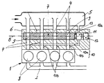
- the reference number 1 denotes a four-cylinder internal combustion engine, which in addition to a usual exhaust manifold 2 the individual cylinders 3 assigned intake ducts 4, by an intake manifold 5 are supplied with intake air f for the internal combustion engine 1.
- the individual intake ducts 4 open into a so-called valve housing 6 and run separately from one another through this to the internal combustion engine 1 or to the cylinder head of the same and lead within the same then to the individual cylinders 3.
- a roller slide 7 can be rotated about its axis of rotation 8 stored.
- the circular cylindrical roller valve 7 (the cylinder axis is equal to the axis of rotation 8) has four perpendicular to the rotary slide axis of rotation 8 passing passages 9, which by turning the Roller slide 7 each with the intake channels running in the slide housing 6 4 can be brought into or out of overlap.
- the passage passages 9 can thus position-dependent a part of the (in the drawing above) and behind (in the drawing below) the roller valve 7 in the valve housing 6 extending intake channels 4 form or also do not form.
- This idle air duct system 10 consists of a running in the valve housing 6 and from the same outside, namely supplied by the intake manifold 5 Idle air duct 10a, for which the rotary valve 11 is an adjustable throttle body forms, and the downstream of the rotary valve 11 in in the individual Intake channels 4 branching sub-channels 10b branches.
- the idle air duct system 10 including the associated control element is provided in the slide housing 6 in the form of the rotary slide valve 11, the construction effort and the required space is as small as possible held. In particular, are for the idle air control of the multi-cylinder Internal combustion engine 1 no further complex air lines, line connections and the like. This also increases functional reliability. Finally, during the assembly process, the prefabricated valve housing 6 including the filling control system (namely the roller valve 7) and the idle control system (namely, the idle air duct system 10 with the rotary valve 11) as a prefabricated pre-assembly unit Internal combustion engine 1 or flanged to the cylinder head thereof become.
- the rotary valve 11 is preferably arranged coaxially with the roller valve 7, so that for a rotational movement of the roller valve 7 and the Rotary valve 11, a single actuator 12 can be provided.
- This actuator 12 may be, for example, an electrical one Act actuator, its output axis with the axes of rotation 8 of the roller valve 7 and the rotary valve 11 coincides.
- This servomotor or this actuator 12 can be arranged coaxially and one behind the other Then turn rotary valve 11 and roller valve 7 together or position as desired when the roller valve 7 with respect its rotational movement coupled to the rotary valve 11 or can be coupled is. This is by a between the rotary valve 11 and the Roller slide 7 coaxial to the axis of rotation 8, not shown Coupling element 13 realizable.
- This coupling element 13 can, for example, be a simple mechanical one act indissoluble coupling, which is then a rigid coupling caused between the rotary valve 11 and the roller valve 7. This has with the result that when the roller valve 7 is closed, the actuator 12 by appropriate control the idle control of the internal combustion engine 1 takes over and suitably positions the rotary valve 11, whereby care must be taken to ensure that in the course of this idle control the roller valve 7 does not reach its partially open position. The the same actuator 12 rotates and also opens the roller valve 7 in the desired manner if the internal combustion engine 1 with partial load or Full load is to be operated. It must be ensured that the Rotary slide 11 over the entire range of rotation angle of the roller valve 7 is clear.
- the coupling element 13 can also be a Act driver clutch (e.g. designed as a dog clutch), see above that - starting from a closed position of the roller valve 7 - initially only the rotary valve 11 connected to the actuator 12 is and thus is rotated by this, and that at a larger angle of rotation this rotary valve 11 in the opening direction of the roller valve 7 the latter via the driver clutch or the coupling element 13 entrained and thus rotated de facto in the opening direction becomes.
- Act driver clutch e.g. designed as a dog clutch
- roller valve 7 and for the rotary valve 11 each have a separate actuator for to provide respective twisting movement
- a variety can further details, particularly of a constructive nature, deviate from that shown Embodiment can be designed without the content of the claims to leave.
Landscapes
- Engineering & Computer Science (AREA)
- Chemical & Material Sciences (AREA)
- Combustion & Propulsion (AREA)
- Mechanical Engineering (AREA)
- General Engineering & Computer Science (AREA)
- Control Of Throttle Valves Provided In The Intake System Or In The Exhaust System (AREA)
- Valve-Gear Or Valve Arrangements (AREA)
Abstract
Description
Die Lösung dieser Aufgabe ist gekennzeichnet durch einen im Schiebergehäuse vorgesehenen und einem Leerlauf-Luftkanalsystem zugeordneten Drehschieber für die Leerlauf-Luftregelung der Brennkraftmaschine. Vorteilhafte Aus- und Weiterbildungen sind Inhalt der Unteransprüche.
- 1
- Brennkraftmaschine
- 2
- Abgaskrümmer
- 3
- Zylinder
- 4
- Ansaugkanal
- 5
- Ansaugluftverteiler
- 6
- Schiebergehäuse
- 7
- Walzenschieber
- 8
- Drehachse
- 9
- Durchtrittspassage
- 10
- Leerlauf-Luftkanalsystem
- 10a
- Leerlauf-Luftkanal
- 10b
- Teilkanal
- 11
- Drehschieber
- 12
- Betätigungsorgan
- 13
- Kupplungselement
Claims (5)
- Mehrzylindrige Brennkraftmaschine (1) mit einer Walzenschieber-Anordnung für die Füllungssteuerung, mit einem in einem die Zylinder-Ansaugkanäle (4) aufweisenden Schiebergehäuse (6) verdrehbar gelagerten kreiszylindrischen Walzenschieber (7), dessen senkrecht zur Walzenschieber-Drehachse (8) verlaufende Durchtrittspassagen (9) durch Verdrehen des Walzenschiebers (7) mit den Ansaugkanälen (4) in oder außer Überdeckung bringbar sind,
gekennzeichnet durch einen im Schiebergehäuse (6) vorgesehenen und einem Leerlauf-Luftkanalsystem (10) zugeordneten Drehschieber (11) für die Leerlauf-Luftregelung der Brennkraftmaschine (1). - Mehrzylindrige Brennkraftmaschine nach Anspruch 1,
dadurch gekennzeichnet, daß der Drehschieber (11) koaxial zum Walzenschieber (7) angeordnet ist. - Mehrzylindrige Brennkraftmaschine nach Anspruch 1 oder 2,
dadurch gekennzeichnet, daß der Walzenschieber (7) hinsichtlich seiner Verdrehbewegung an den Drehschieber (11) angekoppelt oder ankoppelbar ist. - Mehrzylindrige Brennkraftmaschine nach einem der vorangegangenen Ansprüche,
gekennzeichnet durch ein gemeinsames Betätigungsorgan (12) für den Walzenschieber (7) und den Drehschieber (11). - Mehrzylindrige Brennkraftmaschine nach einem der vorangegangenen Ansprüche,
dadurch gekennzeichnet, daß das Leerlauf-Luftkanalsystem (10) aus einem im Schiebergehäuse (6) verlaufenden und von außerhalb desselben versorgten Leerlauf-Luftkanal (10a) besteht, für den der Drehschieber (11) ein einstellbares Drosselorgan bildet, und der sich stromab des Drehschiebers (11) in in den einzelnen Ansaugkanälen (4) mündende Teilkanäle (10b) verzweigt.
Applications Claiming Priority (2)
| Application Number | Priority Date | Filing Date | Title |
|---|---|---|---|
| DE19815743 | 1998-04-08 | ||
| DE19815743A DE19815743A1 (de) | 1998-04-08 | 1998-04-08 | Mehrzylindrige Brennkraftmaschine mit einer Walzenschieber-Anordnung |
Publications (3)
| Publication Number | Publication Date |
|---|---|
| EP0949412A2 true EP0949412A2 (de) | 1999-10-13 |
| EP0949412A3 EP0949412A3 (de) | 2000-05-31 |
| EP0949412B1 EP0949412B1 (de) | 2002-01-16 |
Family
ID=7863988
Family Applications (1)
| Application Number | Title | Priority Date | Filing Date |
|---|---|---|---|
| EP99105356A Expired - Lifetime EP0949412B1 (de) | 1998-04-08 | 1999-03-16 | Mehrzylindrige Brennkraftmaschine mit einer Walzenschieber-Anordnung |
Country Status (2)
| Country | Link |
|---|---|
| EP (1) | EP0949412B1 (de) |
| DE (2) | DE19815743A1 (de) |
Family Cites Families (3)
| Publication number | Priority date | Publication date | Assignee | Title |
|---|---|---|---|---|
| DE3217251A1 (de) * | 1982-05-07 | 1983-11-10 | Bayerische Motoren Werke AG, 8000 München | Ansaugsystem fuer gemischverdichtende, fremdgezuendete mehrzylinder-brennkraftmaschinen |
| GB2165886A (en) * | 1984-10-23 | 1986-04-23 | Ford Motor Co | An inlet manifold for an i c engine |
| JP2753874B2 (ja) * | 1989-12-06 | 1998-05-20 | マツダ株式会社 | 多気筒エンジンの吸気装置 |
-
1998
- 1998-04-08 DE DE19815743A patent/DE19815743A1/de not_active Withdrawn
-
1999
- 1999-03-16 EP EP99105356A patent/EP0949412B1/de not_active Expired - Lifetime
- 1999-03-16 DE DE59900613T patent/DE59900613D1/de not_active Expired - Fee Related
Non-Patent Citations (1)
| Title |
|---|
| None |
Also Published As
| Publication number | Publication date |
|---|---|
| DE19815743A1 (de) | 1999-10-14 |
| EP0949412B1 (de) | 2002-01-16 |
| DE59900613D1 (de) | 2002-02-21 |
| EP0949412A3 (de) | 2000-05-31 |
Similar Documents
| Publication | Publication Date | Title |
|---|---|---|
| DE102016208159B4 (de) | Turbine für einen Abgasturbolader mit zweiflutigem Turbinengehäuse und einem Ventil zur Flutenverbindung | |
| DE102012207617B4 (de) | Turbogeladener Verbrennungsmotor mit dedizierter Abgasrückführung | |
| DE69505763T2 (de) | Ansaugrohr mit Schwenkklappen für eine Brennkraftmaschine | |
| DE102010004657B4 (de) | Frischgasversorgungsvorrichtung für eine Verbrennungsmaschine und Verfahren zum Betrieb einer solchen Frischgasversorgungsvorrichtung | |
| DE102010016284A1 (de) | Luftansaugvorrichtung für einen Verbrennungsmotor | |
| DE3040201A1 (de) | Einlass-system | |
| DE102007033675A1 (de) | Abgasrückführvorrichtung für eine Verbrennungskraftmaschine | |
| EP0272373A1 (de) | Drosselklappenstutzen für eine Brennkraftmaschine | |
| DE19929956C5 (de) | Abgasrückführventil | |
| DE4423427A1 (de) | Ansauganlage für eine Mehrzylinder-Brennkraftmaschine | |
| DE102015223740A1 (de) | Wastegate-Baugruppe für einen Turbolader | |
| EP0731878B1 (de) | Vorrichtung zur regelung der leerlaufdrehzahl einer brennkraftmaschine | |
| DE3200521C2 (de) | ||
| DE60203475T2 (de) | Drosselklappe und Drossel | |
| DE69806506T2 (de) | Turbolader mit in der turbine integriertem abgasrückführungsventil und abblaseventil | |
| EP0949412B1 (de) | Mehrzylindrige Brennkraftmaschine mit einer Walzenschieber-Anordnung | |
| DE2928590A1 (de) | Frischluftleitung fuer hubkolbenbrennkraftmaschinen mit einlassdrallkanaelen | |
| DE3545811C2 (de) | ||
| EP0370218B1 (de) | Viertakt-Brennkraftmaschine | |
| DE3923924C2 (de) | Steuervorrichtung für das Saugrohrsystem einer Fahrzeugbrennkraftmaschine | |
| DE19908962C2 (de) | Brennkraftmaschine mit innerer Verbrennung | |
| EP2432979B1 (de) | Gehäuse einer frischgasversorgungseinrichtung für eine verbrennungsmaschine und frischgasversorgungseinrichtung | |
| DE19815739A1 (de) | Walzenschieber-Anordnung | |
| DE60109909T2 (de) | Vergaser für einen verbrennungsmotor | |
| DE102004008255A1 (de) | Vorrichtung zur Änderung der Ladungsbewegung der Ansaugluft in Brennkraftmaschinen |
Legal Events
| Date | Code | Title | Description |
|---|---|---|---|
| PUAI | Public reference made under article 153(3) epc to a published international application that has entered the european phase |
Free format text: ORIGINAL CODE: 0009012 |
|
| AK | Designated contracting states |
Kind code of ref document: A2 Designated state(s): DE FR GB IT |
|
| AX | Request for extension of the european patent |
Free format text: AL;LT;LV;MK;RO;SI |
|
| PUAL | Search report despatched |
Free format text: ORIGINAL CODE: 0009013 |
|
| AK | Designated contracting states |
Kind code of ref document: A3 Designated state(s): AT BE CH CY DE DK ES FI FR GB GR IE IT LI LU MC NL PT SE |
|
| AX | Request for extension of the european patent |
Free format text: AL;LT;LV;MK;RO;SI |
|
| RIC1 | Information provided on ipc code assigned before grant |
Free format text: 7F 02D 9/16 A, 7F 02M 35/108 B |
|
| 17P | Request for examination filed |
Effective date: 20000614 |
|
| AKX | Designation fees paid |
Free format text: DE FR GB IT |
|
| GRAG | Despatch of communication of intention to grant |
Free format text: ORIGINAL CODE: EPIDOS AGRA |
|
| GRAG | Despatch of communication of intention to grant |
Free format text: ORIGINAL CODE: EPIDOS AGRA |
|
| GRAH | Despatch of communication of intention to grant a patent |
Free format text: ORIGINAL CODE: EPIDOS IGRA |
|
| 17Q | First examination report despatched |
Effective date: 20010615 |
|
| GRAH | Despatch of communication of intention to grant a patent |
Free format text: ORIGINAL CODE: EPIDOS IGRA |
|
| GRAH | Despatch of communication of intention to grant a patent |
Free format text: ORIGINAL CODE: EPIDOS IGRA |
|
| GRAA | (expected) grant |
Free format text: ORIGINAL CODE: 0009210 |
|
| REG | Reference to a national code |
Ref country code: GB Ref legal event code: IF02 |
|
| AK | Designated contracting states |
Kind code of ref document: B1 Designated state(s): DE FR GB IT |
|
| GBT | Gb: translation of ep patent filed (gb section 77(6)(a)/1977) |
Effective date: 20020116 |
|
| REF | Corresponds to: |
Ref document number: 59900613 Country of ref document: DE Date of ref document: 20020221 |
|
| ET | Fr: translation filed | ||
| PLBE | No opposition filed within time limit |
Free format text: ORIGINAL CODE: 0009261 |
|
| STAA | Information on the status of an ep patent application or granted ep patent |
Free format text: STATUS: NO OPPOSITION FILED WITHIN TIME LIMIT |
|
| 26N | No opposition filed | ||
| PGFP | Annual fee paid to national office [announced via postgrant information from national office to epo] |
Ref country code: IT Payment date: 20060331 Year of fee payment: 8 |
|
| PGFP | Annual fee paid to national office [announced via postgrant information from national office to epo] |
Ref country code: DE Payment date: 20060426 Year of fee payment: 8 |
|
| PGFP | Annual fee paid to national office [announced via postgrant information from national office to epo] |
Ref country code: GB Payment date: 20070329 Year of fee payment: 9 |
|
| PG25 | Lapsed in a contracting state [announced via postgrant information from national office to epo] |
Ref country code: DE Free format text: LAPSE BECAUSE OF NON-PAYMENT OF DUE FEES Effective date: 20071002 |
|
| PGFP | Annual fee paid to national office [announced via postgrant information from national office to epo] |
Ref country code: FR Payment date: 20070329 Year of fee payment: 9 |
|
| GBPC | Gb: european patent ceased through non-payment of renewal fee |
Effective date: 20080316 |
|
| REG | Reference to a national code |
Ref country code: FR Ref legal event code: ST Effective date: 20081125 |
|
| PG25 | Lapsed in a contracting state [announced via postgrant information from national office to epo] |
Ref country code: FR Free format text: LAPSE BECAUSE OF NON-PAYMENT OF DUE FEES Effective date: 20080331 |
|
| PG25 | Lapsed in a contracting state [announced via postgrant information from national office to epo] |
Ref country code: GB Free format text: LAPSE BECAUSE OF NON-PAYMENT OF DUE FEES Effective date: 20080316 |
|
| PG25 | Lapsed in a contracting state [announced via postgrant information from national office to epo] |
Ref country code: IT Free format text: LAPSE BECAUSE OF NON-PAYMENT OF DUE FEES Effective date: 20070316 |