EP0949136A1 - Energieaufnahmeeinheit mit doppelter Wicklung für eine Kraftfahrzeuglenksäule - Google Patents
Energieaufnahmeeinheit mit doppelter Wicklung für eine Kraftfahrzeuglenksäule Download PDFInfo
- Publication number
- EP0949136A1 EP0949136A1 EP99400363A EP99400363A EP0949136A1 EP 0949136 A1 EP0949136 A1 EP 0949136A1 EP 99400363 A EP99400363 A EP 99400363A EP 99400363 A EP99400363 A EP 99400363A EP 0949136 A1 EP0949136 A1 EP 0949136A1
- Authority
- EP
- European Patent Office
- Prior art keywords
- support
- double winding
- energy absorption
- absorption device
- windings
- Prior art date
- Legal status (The legal status is an assumption and is not a legal conclusion. Google has not performed a legal analysis and makes no representation as to the accuracy of the status listed.)
- Granted
Links
- 238000004804 winding Methods 0.000 title claims abstract description 67
- 238000010521 absorption reaction Methods 0.000 claims description 29
- 210000005069 ears Anatomy 0.000 claims description 10
- 230000035939 shock Effects 0.000 claims description 9
- 229910052751 metal Inorganic materials 0.000 claims description 7
- 239000002184 metal Substances 0.000 claims description 5
- 238000011084 recovery Methods 0.000 claims description 4
- 230000021715 photosynthesis, light harvesting Effects 0.000 description 4
- 208000031968 Cadaver Diseases 0.000 description 2
- 230000009977 dual effect Effects 0.000 description 1
- 238000004519 manufacturing process Methods 0.000 description 1
- 238000000034 method Methods 0.000 description 1
- 238000005476 soldering Methods 0.000 description 1
Images


Classifications
-
- F—MECHANICAL ENGINEERING; LIGHTING; HEATING; WEAPONS; BLASTING
- F16—ENGINEERING ELEMENTS AND UNITS; GENERAL MEASURES FOR PRODUCING AND MAINTAINING EFFECTIVE FUNCTIONING OF MACHINES OR INSTALLATIONS; THERMAL INSULATION IN GENERAL
- F16F—SPRINGS; SHOCK-ABSORBERS; MEANS FOR DAMPING VIBRATION
- F16F7/00—Vibration-dampers; Shock-absorbers
- F16F7/12—Vibration-dampers; Shock-absorbers using plastic deformation of members
- F16F7/123—Deformation involving a bending action, e.g. strap moving through multiple rollers, folding of members
-
- B—PERFORMING OPERATIONS; TRANSPORTING
- B62—LAND VEHICLES FOR TRAVELLING OTHERWISE THAN ON RAILS
- B62D—MOTOR VEHICLES; TRAILERS
- B62D1/00—Steering controls, i.e. means for initiating a change of direction of the vehicle
- B62D1/02—Steering controls, i.e. means for initiating a change of direction of the vehicle vehicle-mounted
- B62D1/16—Steering columns
- B62D1/18—Steering columns yieldable or adjustable, e.g. tiltable
- B62D1/19—Steering columns yieldable or adjustable, e.g. tiltable incorporating energy-absorbing arrangements, e.g. by being yieldable or collapsible
- B62D1/195—Yieldable supports for the steering column
Definitions
- the present invention relates to a dual energy absorption device winding for vehicle steering column automobile.
- the device according to the invention applies in particular to a steering column adjustable in depth or tilt or to a column of steering adjustable in depth and tilt, comprising a steering shaft mounted in a body tube which is supported and locked in position desired, the tube-body being connected by an assembly support to the vehicle chassis or to an element of the body
- the purpose of the present invention is to provide an energy absorption device, which puts in works a wire of simple form and easy to realize, which allows to absorb exactly a quantity predetermined energy to dissipate, and which mounts easily in the size of the columns of existing management.
- the double winding comprises two helical windings in opposite directions, having identical number of turns. Said windings are connected by a central loop, which cooperates with the movable support connected to the tube-body, so that during the shock, the two windings are unwound simultaneously to dissipate the desired amount of energy.
- the double winding comprises two helical windings in opposite directions, having numbers of different turns. Said windings are connected by a central loop, which cooperates with the movable support element connected to the body tube, so that during the shock, at first the two windings are unrolled simultaneously, and secondly only one winding or unwound to adjust the energy dissipation in the weather.
- the section of the metal element of the double winding is round, and in others achievements, this section is square or rectangular or other.
- the energy absorption device thus has the advantage of having a very simple structure to make, with a guarantee manufacturing quality when made in very large series, as is the case in automobile industry.
- the device easily adapts to the size of the columns of existing management.
- the double system winding increases the effort absorbed while keeping the same unwinding race. he also offers the advantage of saving coins and very easy to fix on its support, without any parts or soldering for the maintain.
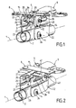
- a motor vehicle steering column includes a steering shaft 1 which is mounted rotating in a tube-body 2, as shown in Figures 1 to 5.
- the tube-body 2 is connected to a support assembly 6 by a system 4 of adjustment in depth and / or tilt.
- the invention can also apply to a steering column not adjustable, the tube-body 2 of which is fixedly connected to the support assembly 6.
- the support assembly 6 comprises a fixed support 8 and a mobile support 9.
- the fixed support 8 is integral with the chassis 10 of the vehicle or an element of bodywork.
- the mobile support 9 is connected to the tube-body 2 by the adjustment system in position 4.
- the mobile support 9 is connected to the support element fixed 8 and is locked on it with force of a determined value, which takes into account the shock to absorb in order to allow in this case the support mobile 9 to slide in the fixed support 8.
- the fixed support 8 has a base 15 with two ears 11 and 12 substantially parallel and vertical which are mounted on this base 15.
- Each of ears 11 and 12 has a through hole respective 13 and 14 of the support holding axis mobile 9.
- the mobile support 9 has two portions side 21 and 22 substantially parallel and vertical and a connection portion 20 substantially horizontal.
- the mobile support 9 comes engage between the two ears 11 and 12 of the support fixed 8 through its two portions side 21 and 22.
- Each of the lateral portions 21 and 22 has at its upper part a respective oblong hole 25 and 26 passage of the holding axis of the mobile support 9.
- each of these oblong holes 25 and 26 corresponds to the energy recovery stroke.
- Each of the lateral portions 21 and 22 has at its lower part a respective through hole 23 and 24 of the axis of the adjustment system 4.
- the energy absorption device is arranged so as to act in a direction substantially parallel to the axis of the steering column.
- the energy absorption device steering column comprises a double winding 3 of a metallic element, which has a constant section determined to meet the energy dissipation requested.
- the double winding 3 has two windings, which have the same axis and which are connected by a central portion.
- the double winding 3 is mounted on an element 47 rotating on a fixed axis 48 integral with the fixed support 8. Its central portion is mounted on the support mobile 9 connected to the tube-body 2 so that in case shock, said movable support 9 connected to the tube-body 2 and therefore at the wheel pushes the central portion of said double winding 3 in order to unwind said double winding 3 by absorbing the energy to be dissipated.
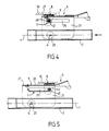
- the double winding 3 consists by two helical windings 31 and 32 in direction opposite, having a round section and the same number of turns, which are connected by a central loop 34.
- the central loop 34 cooperates with the mobile support 9 connected to the tube-body 2.
- the movable support 9 acts on said central loop 34 by pushing it during a shock, so that the two windings 31 and 32 are held simultaneously to dispel the amount of energy required.
- the rotating element 47 is arranged on the fixed axis 48, which is mounted in the two through holes 13 and 14 of the ears 11 and 12 of the fixed support 8.
- the axis fixed 48 passes through the two oblong holes 25 and 26 of the mobile support 9, and it is blocked with a force of tightening of a determined value on both ears 11 and 12 of the fixed support 8.
- the fixed axis 48 of the rotating element 47 constitutes thus the holding axis of the mobile support 9 in the fixed support 8.
- each of the oblong holes 25 and 26 corresponds to the energy recovery run.
- the double winding 3 is mounted on the rotating element 47 and is hooked by its central loop 34 to a stud 29 arranged in the connection portion 20 of the mobile support 9 in passing over said pin 29 and engaging in notches 27, 28 formed on each side of said pin 29, so that in the event of an impact, the steering wheel with the body-tube 2 and the movable support 9 move towards the front of the vehicle by driving the double winding 3, which takes place around the rotating element 47 disposed on the fixed axis 48 secured to the fixed support 8.
- the double winding 3 is constituted by two helical windings 35 and 36 in opposite directions having the same number of turns, the two windings 35 and 36 being connected by a central loop 38 and having a square section.
- the central loop 38 cooperates with the mobile support 9 connected to the body tube 2 and which acts on said central loop 38 in the pushing in a shock so that the two windings 35 and 36 are unwound simultaneously in order to dissipate the energy required.
- the mounting of the rotating element 47 is identical to the assembly described above for Figures 1, 2, 4 and 5.
- the double winding 3 is mounted on the rotating element 47, and it is hung by its central loop 38 to a stud 29 arranged in the connection portion 20 of the mobile support 9 in passing over said pin 29 and engaging in notches 27, 28 formed on each side of said pin 29.
- the steering wheel with the body tube 2 and the mobile support 9 move towards the front of the vehicle driving the double winding 3, which takes place around the element turning 47 disposed on the fixed axis 48 integral with the fixed support 8.
- the double winding 3 is constituted by two helical windings 39 and 40 in direction opposite, having different numbers of turns, which are connected by a central loop 42 and have a round section.
- the central loop 42 cooperates with the mobile support 9 connected to the tube-body 2 and which acts on said central loop 42 by pushing it during of a shock, so that, at first the two windings 39 and 40 are unwound simultaneously, and that in a second time only one winding 40 is unwound in order to adjust the energy dissipation over time.
- the mounting of different elements is identical to the assembly described previously for Figures 1, 2, 4 and 5.
- the section can also be square. This type of section has been shown in Figure 3.
- the section of the double winding can alternatively be rectangular or other.
Landscapes
- Engineering & Computer Science (AREA)
- Mechanical Engineering (AREA)
- General Engineering & Computer Science (AREA)
- Chemical & Material Sciences (AREA)
- Combustion & Propulsion (AREA)
- Transportation (AREA)
- Steering Controls (AREA)
- Automatic Cycles, And Cycles In General (AREA)
Applications Claiming Priority (2)
| Application Number | Priority Date | Filing Date | Title |
|---|---|---|---|
| FR9802668A FR2775646B1 (fr) | 1998-03-03 | 1998-03-03 | Dispositif d'absorption d'energie a double enroulement pour colonne de direction de vehicule automobile |
| FR9802668 | 1998-03-03 |
Publications (2)
| Publication Number | Publication Date |
|---|---|
| EP0949136A1 true EP0949136A1 (de) | 1999-10-13 |
| EP0949136B1 EP0949136B1 (de) | 2002-05-02 |
Family
ID=9523671
Family Applications (1)
| Application Number | Title | Priority Date | Filing Date |
|---|---|---|---|
| EP99400363A Expired - Lifetime EP0949136B1 (de) | 1998-03-03 | 1999-02-16 | Energieaufnahmeeinheit mit doppelter Wicklung für eine Kraftfahrzeuglenksäule |
Country Status (5)
| Country | Link |
|---|---|
| US (1) | US6183012B1 (de) |
| EP (1) | EP0949136B1 (de) |
| DE (1) | DE69901366T2 (de) |
| ES (1) | ES2174577T3 (de) |
| FR (1) | FR2775646B1 (de) |
Cited By (4)
| Publication number | Priority date | Publication date | Assignee | Title |
|---|---|---|---|---|
| GB2357565A (en) * | 1999-12-21 | 2001-06-27 | Latchways Plc | Energy absorber |
| GB2368818A (en) * | 2000-11-08 | 2002-05-15 | Nastech Europ Ltd | Collapsible steering column assembly for a vehicle |
| US7104371B2 (en) | 2000-05-18 | 2006-09-12 | Keyguard Limited | Energy absorber |
| US7188704B2 (en) | 1999-12-21 | 2007-03-13 | Keyguard Limited | Energy absorber |
Families Citing this family (23)
| Publication number | Priority date | Publication date | Assignee | Title |
|---|---|---|---|---|
| JP3727004B2 (ja) * | 1999-09-10 | 2005-12-14 | 光洋精工株式会社 | 衝撃吸収式ステアリング装置及びこれに用いる取付部材 |
| FR2801269B1 (fr) * | 1999-11-19 | 2002-02-08 | Nacam | Dispositif d'absorption d'energie modulaire a charges pyrotechniques d'une colonne de direction de vehicule automobile |
| FR2805512B1 (fr) * | 2000-02-24 | 2002-05-03 | Nacam | Dispositif de guidage lineaire d'une colonne de direction |
| FR2812262B1 (fr) * | 2000-07-26 | 2003-01-10 | Nacam | Dispositif d'absorption d'energie modulable a charges pyrotechniques suivant l'axe d'une colonne de direction de vehicule automobile |
| JP4667676B2 (ja) | 2000-09-19 | 2011-04-13 | エヌエスケー ステアリング システムズ ヨーロッパ リミテッド | 車両のステアリングコラム制御装置 |
| JP2003327133A (ja) * | 2002-05-13 | 2003-11-19 | Koyo Seiko Co Ltd | ステアリング装置 |
| JP4134601B2 (ja) * | 2002-06-04 | 2008-08-20 | 日本精工株式会社 | 車両用チルト式ステアリングコラム装置 |
| US6799486B2 (en) | 2002-06-07 | 2004-10-05 | Delphi Technologies, Inc. | Interactive energy absorbing system |
| JP4124021B2 (ja) * | 2002-10-07 | 2008-07-23 | トヨタ自動車株式会社 | 衝撃吸収式ステアリングコラム装置 |
| GB2404633B (en) * | 2003-08-06 | 2005-07-20 | Nsk Steering Sys Europ Ltd | Energy absorption device for vehicle steering column |
| KR100510416B1 (ko) * | 2003-09-06 | 2005-08-26 | 현대모비스 주식회사 | 충격 흡수식 로어틸트타입 조향컬럼 |
| DE10341604B4 (de) * | 2003-09-10 | 2008-08-28 | Daimler Ag | Lenksäulenanordnung mit einer in ihrer Neigung und Länge veränderbaren Lenksäule |
| DE10341704B4 (de) * | 2003-09-10 | 2008-10-30 | Daimler Ag | Lenksäulenanordnung mit einer in ihrer Neigung und Länge veränderbaren Lenksäule |
| US7178833B2 (en) * | 2004-03-15 | 2007-02-20 | Delphi Technologies, Inc. | Steering column assembly with vertical capsules |
| US7055647B2 (en) * | 2004-07-02 | 2006-06-06 | Nacam France Sa | Electrically-assisted steering mechanism for vehicles |
| DE102004042283B4 (de) * | 2004-09-01 | 2009-03-19 | Daimler Ag | Lenksäulenanordnung |
| US7306259B2 (en) * | 2004-10-14 | 2007-12-11 | Delphi Technologies, Inc. | Lock for tilting and telescoping steering column |
| KR100836909B1 (ko) | 2006-07-12 | 2008-06-11 | 현대자동차주식회사 | 차량용 스티어링 컬럼의 충격 흡수 시스템 |
| KR101115084B1 (ko) * | 2008-02-29 | 2012-02-28 | 주식회사 만도 | 자동차의 충격 흡수식 조향 컬럼 |
| DE102009059159B3 (de) * | 2009-12-16 | 2011-01-27 | Thyssenkrupp Presta Ag | Lenksäule für ein Kraftfahrzeug |
| CN101927782B (zh) * | 2010-08-19 | 2012-07-18 | 浙江吉利汽车研究院有限公司 | 转向管柱的压溃吸能机构 |
| GB201303513D0 (en) | 2013-02-27 | 2013-04-10 | Trw Ltd | A steering column assembly |
| PL234835B1 (pl) * | 2016-11-25 | 2020-04-30 | Przemyslowy Inst Motoryzacji | Inteligentny absorber |
Citations (1)
| Publication number | Priority date | Publication date | Assignee | Title |
|---|---|---|---|---|
| DE19510615A1 (de) * | 1995-03-23 | 1996-09-26 | Lemfoerder Metallwaren Ag | Befestigung einer Lenksäule in einem Kraftfahrzeug |
Family Cites Families (4)
| Publication number | Priority date | Publication date | Assignee | Title |
|---|---|---|---|---|
| US3126072A (en) * | 1964-03-24 | Energy | ||
| US4531619A (en) * | 1982-09-24 | 1985-07-30 | Eckels Robert E | Collapsible steering column |
| US5961146A (en) * | 1996-01-18 | 1999-10-05 | Nsk Ltd. | Shock absorbing type steering column assembly |
| US6019391A (en) * | 1998-05-04 | 2000-02-01 | General Motors Corporation | Steering column for motor vehicle |
-
1998
- 1998-03-03 FR FR9802668A patent/FR2775646B1/fr not_active Expired - Fee Related
-
1999
- 1999-02-16 DE DE69901366T patent/DE69901366T2/de not_active Expired - Lifetime
- 1999-02-16 EP EP99400363A patent/EP0949136B1/de not_active Expired - Lifetime
- 1999-02-16 ES ES99400363T patent/ES2174577T3/es not_active Expired - Lifetime
- 1999-02-25 US US09/257,009 patent/US6183012B1/en not_active Expired - Lifetime
Patent Citations (1)
| Publication number | Priority date | Publication date | Assignee | Title |
|---|---|---|---|---|
| DE19510615A1 (de) * | 1995-03-23 | 1996-09-26 | Lemfoerder Metallwaren Ag | Befestigung einer Lenksäule in einem Kraftfahrzeug |
Cited By (7)
| Publication number | Priority date | Publication date | Assignee | Title |
|---|---|---|---|---|
| GB2357565A (en) * | 1999-12-21 | 2001-06-27 | Latchways Plc | Energy absorber |
| GB2357565B (en) * | 1999-12-21 | 2003-08-06 | Latchways Plc | Energy absorber |
| US7188704B2 (en) | 1999-12-21 | 2007-03-13 | Keyguard Limited | Energy absorber |
| US7104371B2 (en) | 2000-05-18 | 2006-09-12 | Keyguard Limited | Energy absorber |
| GB2368818A (en) * | 2000-11-08 | 2002-05-15 | Nastech Europ Ltd | Collapsible steering column assembly for a vehicle |
| GB2368818B (en) * | 2000-11-08 | 2004-03-17 | Nastech Europ Ltd | Collapsible steering column assembly for a vehicle |
| US6820899B2 (en) | 2000-11-08 | 2004-11-23 | Nsk Steering Systems Europe Limited | Collapsible steering column assembly for a vehicle |
Also Published As
| Publication number | Publication date |
|---|---|
| FR2775646A1 (fr) | 1999-09-10 |
| DE69901366D1 (de) | 2002-06-06 |
| FR2775646B1 (fr) | 2000-05-12 |
| EP0949136B1 (de) | 2002-05-02 |
| DE69901366T2 (de) | 2002-11-21 |
| ES2174577T3 (es) | 2002-11-01 |
| US6183012B1 (en) | 2001-02-06 |
Similar Documents
| Publication | Publication Date | Title |
|---|---|---|
| EP0949136B1 (de) | Energieaufnahmeeinheit mit doppelter Wicklung für eine Kraftfahrzeuglenksäule | |
| EP1018463B1 (de) | Modulierbare Kraftfahrzeug-Lenksäulen- Energieabsorptionseinrichtung | |
| EP1101687B1 (de) | Pyrotechnisch einstellbare Kraftfahrzeug- Lenksäulenenergieabsorptionseinrichtung | |
| EP1176082B1 (de) | Pyrotechnisch einstellbare Energieabsorptionseinrichtung längs der Achse einer Kraftfahrzeuglenksäule | |
| EP1479593A1 (de) | Modulierbare Kraftfahrzeug-Lenksäulen-Energieabsorptionseinrichtung mit pyrotechnischer Auslösung | |
| EP0662415B1 (de) | Energie-absorbierende Einrichtung mit axialer Führung für eine Kraftfahrzeuglenksäule | |
| EP2155531B1 (de) | Elektrische klemmvorrichtung für eine einstellbare motorfahrzeug-lenksäule | |
| EP0662414B1 (de) | Energieabsorbierende Einrichtung, insbesondere für eine Kraftfahrzeuglenksäule | |
| EP0427584A1 (de) | Befestigungseinrichtung eines schlauchförmigen Organs, insbesondere einer Kraftfahrzeuglenksäule | |
| FR2632922A1 (de) | ||
| EP1127772B1 (de) | Lineare Lenksäulenführungseinrichtung | |
| EP0499508A1 (de) | Lenksäulen-Anordnung für ein Kraftfahrzeug | |
| EP1336546B1 (de) | Einstell- Einrichtung eines Energieaufnehme-Systems einer Kraftfahrzeuglenksäule | |
| EP0655383B1 (de) | Energieaufnehmende Einrichtung für die Lenksäule eines Kraftfahrzeugs | |
| FR2654406A1 (fr) | Fourche avant de motocyclette. | |
| FR2841524A1 (fr) | Dispositif d'absorption d'energie d'une colonne de direction de vehicule automobile | |
| FR2813847A1 (fr) | Systeme de montage d'un garde-boue equipant une roue directrice d'un vehicule | |
| FR2775648A1 (fr) | Dispositif d'absorption d'energie a double enroulement spirale pour colonne de direction de vehicule automobile | |
| FR2834680A1 (fr) | Dispositif de serrage a commande amortie d'une colonne de direction de vehicule automobile | |
| EP0443910A1 (de) | Sperrvorrichtung eines tubulären Organs, insbesondere einer Kraftfahrzeuglenksäule | |
| FR2787842A1 (fr) | Dispositif de serrage en trois points d'un systeme de reglage en position d'un element par rapport a un autre element | |
| FR2775647A1 (fr) | Dispositif d''absorption d'energie a enroulement spirale pour colonne de direction de vehicule automobile | |
| FR2822782A1 (fr) | Dispositif de serrage d'une colonne de direction de vehicule automobile | |
| FR2702440A1 (fr) | Dispositif de réglage de la chasse d'un véhicule, notamment d'un kart. | |
| EP0586306A2 (de) | Regelbares Montagesystem einer Beleuchtungs- oder Blinklichtanlage von Automobilen auf einem festen Teil des Fahrzeugs und damit ausgestattete Anlage |
Legal Events
| Date | Code | Title | Description |
|---|---|---|---|
| PUAI | Public reference made under article 153(3) epc to a published international application that has entered the european phase |
Free format text: ORIGINAL CODE: 0009012 |
|
| AK | Designated contracting states |
Kind code of ref document: A1 Designated state(s): DE ES GB IT SE |
|
| AX | Request for extension of the european patent |
Free format text: AL;LT;LV;MK;RO;SI |
|
| 17P | Request for examination filed |
Effective date: 19991018 |
|
| AKX | Designation fees paid |
Free format text: DE ES GB IT SE |
|
| GRAG | Despatch of communication of intention to grant |
Free format text: ORIGINAL CODE: EPIDOS AGRA |
|
| 17Q | First examination report despatched |
Effective date: 20010807 |
|
| GRAG | Despatch of communication of intention to grant |
Free format text: ORIGINAL CODE: EPIDOS AGRA |
|
| GRAH | Despatch of communication of intention to grant a patent |
Free format text: ORIGINAL CODE: EPIDOS IGRA |
|
| GRAH | Despatch of communication of intention to grant a patent |
Free format text: ORIGINAL CODE: EPIDOS IGRA |
|
| RAP1 | Party data changed (applicant data changed or rights of an application transferred) |
Owner name: NACAM FRANCE SA |
|
| REG | Reference to a national code |
Ref country code: GB Ref legal event code: IF02 |
|
| GRAA | (expected) grant |
Free format text: ORIGINAL CODE: 0009210 |
|
| AK | Designated contracting states |
Kind code of ref document: B1 Designated state(s): DE ES GB IT SE |
|
| REG | Reference to a national code |
Ref country code: GB Ref legal event code: FG4D Free format text: NOT ENGLISH |
|
| REF | Corresponds to: |
Ref document number: 69901366 Country of ref document: DE Date of ref document: 20020606 |
|
| GBT | Gb: translation of ep patent filed (gb section 77(6)(a)/1977) |
Effective date: 20020720 |
|
| REG | Reference to a national code |
Ref country code: ES Ref legal event code: FG2A Ref document number: 2174577 Country of ref document: ES Kind code of ref document: T3 |
|
| PLBE | No opposition filed within time limit |
Free format text: ORIGINAL CODE: 0009261 |
|
| STAA | Information on the status of an ep patent application or granted ep patent |
Free format text: STATUS: NO OPPOSITION FILED WITHIN TIME LIMIT |
|
| 26N | No opposition filed |
Effective date: 20030204 |
|
| PGFP | Annual fee paid to national office [announced via postgrant information from national office to epo] |
Ref country code: SE Payment date: 20050210 Year of fee payment: 7 |
|
| PGFP | Annual fee paid to national office [announced via postgrant information from national office to epo] |
Ref country code: ES Payment date: 20050218 Year of fee payment: 7 |
|
| PG25 | Lapsed in a contracting state [announced via postgrant information from national office to epo] |
Ref country code: SE Free format text: LAPSE BECAUSE OF NON-PAYMENT OF DUE FEES Effective date: 20060217 Ref country code: ES Free format text: LAPSE BECAUSE OF NON-PAYMENT OF DUE FEES Effective date: 20060217 |
|
| PGFP | Annual fee paid to national office [announced via postgrant information from national office to epo] |
Ref country code: IT Payment date: 20060228 Year of fee payment: 8 |
|
| EUG | Se: european patent has lapsed | ||
| REG | Reference to a national code |
Ref country code: ES Ref legal event code: FD2A Effective date: 20060217 |
|
| PG25 | Lapsed in a contracting state [announced via postgrant information from national office to epo] |
Ref country code: IT Free format text: LAPSE BECAUSE OF NON-PAYMENT OF DUE FEES Effective date: 20070216 |
|
| PGFP | Annual fee paid to national office [announced via postgrant information from national office to epo] |
Ref country code: DE Payment date: 20130219 Year of fee payment: 15 |
|
| REG | Reference to a national code |
Ref country code: DE Ref legal event code: R119 Ref document number: 69901366 Country of ref document: DE |
|
| REG | Reference to a national code |
Ref country code: DE Ref legal event code: R119 Ref document number: 69901366 Country of ref document: DE Effective date: 20140902 |
|
| PG25 | Lapsed in a contracting state [announced via postgrant information from national office to epo] |
Ref country code: DE Free format text: LAPSE BECAUSE OF NON-PAYMENT OF DUE FEES Effective date: 20140902 |
|
| PGFP | Annual fee paid to national office [announced via postgrant information from national office to epo] |
Ref country code: GB Payment date: 20150218 Year of fee payment: 17 |
|
| GBPC | Gb: european patent ceased through non-payment of renewal fee |
Effective date: 20160216 |
|
| PG25 | Lapsed in a contracting state [announced via postgrant information from national office to epo] |
Ref country code: GB Free format text: LAPSE BECAUSE OF NON-PAYMENT OF DUE FEES Effective date: 20160216 |