EP0947846B1 - Magnetic field sensor - Google Patents
Magnetic field sensor Download PDFInfo
- Publication number
- EP0947846B1 EP0947846B1 EP99810214A EP99810214A EP0947846B1 EP 0947846 B1 EP0947846 B1 EP 0947846B1 EP 99810214 A EP99810214 A EP 99810214A EP 99810214 A EP99810214 A EP 99810214A EP 0947846 B1 EP0947846 B1 EP 0947846B1
- Authority
- EP
- European Patent Office
- Prior art keywords
- magnetic field
- hall
- voltage
- contacts
- field sensor
- Prior art date
- Legal status (The legal status is an assumption and is not a legal conclusion. Google has not performed a legal analysis and makes no representation as to the accuracy of the status listed.)
- Expired - Lifetime
Links
Images


Classifications
-
- G—PHYSICS
- G01—MEASURING; TESTING
- G01R—MEASURING ELECTRIC VARIABLES; MEASURING MAGNETIC VARIABLES
- G01R33/00—Arrangements or instruments for measuring magnetic variables
- G01R33/02—Measuring direction or magnitude of magnetic fields or magnetic flux
- G01R33/0206—Three-component magnetometers
-
- G—PHYSICS
- G01—MEASURING; TESTING
- G01R—MEASURING ELECTRIC VARIABLES; MEASURING MAGNETIC VARIABLES
- G01R33/00—Arrangements or instruments for measuring magnetic variables
- G01R33/02—Measuring direction or magnitude of magnetic fields or magnetic flux
- G01R33/06—Measuring direction or magnitude of magnetic fields or magnetic flux using galvano-magnetic devices
- G01R33/07—Hall effect devices
Definitions
- the invention relates to a magnetic field sensor referred to in the preamble of claim 1 Art.
- Hall elements as magnetic field sensors has long been common. Hall elements fabricated using conventional IC technology have all the advantages of these technologies, in particular the high reproducibility of their magnetic and electrical properties at comparatively low cost.
- horizontal Hall elements are used
- vertical Hall elements are used. Vertical Hall elements are electrically shorted to the substrate. It is therefore not readily possible to use two vertical Hall elements, which are rotated by 90 ° and integrated on the same chip, simultaneously to measure the two components B x and B y of the magnetic field B, which are parallel to the chip surface to use.
Abstract
Description
Die Erfindung betrifft einen Magnetfeldsensor der im Oberbegriff des Anspruchs 1 genannten Art.The invention relates to a magnetic field sensor referred to in the preamble of claim 1 Art.
Solche Magnetfeldsensoren eignen sich beispielsweise zur Verwendung in Magnetometern, die zur Messung von zwei oder von allen drei Komponenten eines Magnetfeldes ausgelegt sind.Such magnetic field sensors are suitable, for example, for use in magnetometers, which are used for Measurement of two or all three components of a magnetic field are designed.
Die Verwendung von Hallelementen als Magnetfeldsensoren ist seit langem üblich. Hallelemente, die in herkömmlicher IC-Technologie hergestellt sind, weisen alle Vorteile dieser Technologien auf, insbesondere die hohe Reproduzierbarkeit ihrer magnetischen und elektrischen Eigenschaften bei vergleichsweise geringen Kosten. Zur Messung der Komponente des Magnetfeldes, die senkrecht zur Chipoberfläche ist, werden sogenannte horizontale Hallelemente verwendet, während zur Messung der Komponenten des Magnetfeldes, die parallel zur Chipoberfläche sind, sogenannte vertikale Hallelemente verwendet werden. Vertikale Hallelemente sind elektrisch mit dem Substrat kurzgeschlossen. Es ist deshalb nicht ohne Weiteres möglich, zwei vertikale Hallelemente, die um 90° verdreht und auf dem gleichen Chip integriert sind, gleichzeitig zur Messung der beiden Komponenten Bx und By des Magnetfeldes B, die parallel zur Chipoberfläche sind, zu verwenden. Aus der wissenschaftlichen Literatur sind mehrere Magnetfeldsensoren bekannt, die auf der Struktur des vertikalen Hallelementes basieren, und die die gleichzeitige Messung der beiden Komponenten Bx und By erlauben. Diese Hallelemente weisen fünf Stromkontakte und vier Hallkontakte auf. Aus dem Artikel "A 2-D vertical Hall magnetic field sensor using active carrier confinement and micromachining techniques" von M. Paranjape, L. Landsberger und M. Kahrizi,, paper 295 - PA 12 der Konferenz Transducers 95 - Eurosensors IX) ist es bekannt, die Empfindlichkeit des Hallelementes gegen Übersprechen dadurch zu verkleinern, dass die für den Halleffekt relevanten Zonen mittels mikromechanischer Prozesse als dreidimensionale Oberflächenstrukturen ausgebildet werden. Weiter ist es aus den Artikeln "Multidimensional detection of magnetic fields using CMOS integrated sensors" von M. Paranjape und Lj. Ristic, IEEE Transactions on Magnetics, Vol. 27, No. 6, 1991 und "A 3-D vertical Hall magnetic-field sensor in CMOS technology" von M. Paranjape und I. Filanovsky, Sensors and Actuators A, 34 (1992) bekannt, durch Auftrennen der vier Hallkontakte in je zwei Hallkontakte, so dass insgesamt acht Hallkontakte vorhanden sind, einen Magnetfeldsensor zu konstruieren, der auch die Messung der zur Chipoberfläche senkrechten Komponente Bz des Magnetfeldes B ermöglicht. Die Empfindlichkeit dieser Magnetfeldsensoren bezüglich der Bz-Komponente ist jedoch wesentlich geringer als die Empfmdlichkeit bezüglich der Bx- oder der By-Komponente.The use of Hall elements as magnetic field sensors has long been common. Hall elements fabricated using conventional IC technology have all the advantages of these technologies, in particular the high reproducibility of their magnetic and electrical properties at comparatively low cost. To measure the component of the magnetic field that is perpendicular to the chip surface, so-called horizontal Hall elements are used, while for measuring the components of the magnetic field, which are parallel to the chip surface, so-called vertical Hall elements are used. Vertical Hall elements are electrically shorted to the substrate. It is therefore not readily possible to use two vertical Hall elements, which are rotated by 90 ° and integrated on the same chip, simultaneously to measure the two components B x and B y of the magnetic field B, which are parallel to the chip surface to use. From the scientific literature, several magnetic field sensors are known, which are based on the structure of the vertical Hall element, and allow the simultaneous measurement of the two components B x and B y . These Hall elements have five power contacts and four Hall contacts. It is from the article "A 2-D vertical Hall magnetic field sensor using active carrier confinement and micromachining techniques" by M. Paranjape, L. Landsberger and M. Kahrizi, paper 295 - PA 12 of the conference Transducers 95 - Eurosensors IX) It is known that the sensitivity of the Hall element to crosstalk can be reduced by designing the zones relevant for the Hall effect as three-dimensional surface structures by means of micromechanical processes. Further, it is known from the articles "Multidimensional detection of magnetic fields using CMOS integrated sensors" by M. Paranjape and Lj. Ristic, IEEE Transactions on Magnetics, Vol. 6, 1991 and "A 3-D vertical Hall magnetic-field sensor in CMOS technology" by M. Paranjape and I. Filanovsky, Sensors and Actuators A, 34 (1992) known by dividing the four Hall contacts in two Hall contacts, so that a total of eight Hall contacts are available to construct a magnetic field sensor, which also allows the measurement of the perpendicular to the chip surface component B z of the magnetic field B. However, the sensitivity of these magnetic field sensors to the B z component is significantly less than the sensitivity to the B x or B y component.
Der Erfindung liegt die Aufgabe zugrunde, einen Magnetfeldsensor vorzuschlagen, der einfach herstellbar ist und der geeignet ist, wenigstens zwei, vorzugsweise alle drei Komponenten eines Magnetfeldes mit hoher örtlicher Auflösung zu messen.The invention has for its object to propose a magnetic field sensor, the simple can be produced and which is suitable, at least two, preferably all three components of a Magnetic field with high spatial resolution to measure.
Die genannte Aufgabe wird erfindungsgemäss gelöst durch die Merkmale des Anspruches 1.The stated object is achieved according to the invention by the features of claim 1.
Nachfolgend werden Ausführungsbeispiele der Erfindung anhand der Zeichnung näher erläutert. Embodiments of the invention will be explained in more detail with reference to the drawing.
Es zeigen:
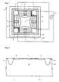
- Fig. 1
- ein Hallelement in der Draufsicht,
- Fig. 2
- einen vertikalen Schnitt durch das Hallelement, das elektrisch mit dem Substrat verbunden ist,
- Fig. 3
- eine Schaltung zur Auswertung der Potentiale an den Spannungskontakten des Hallelementes,
- Fig. 4-6
- weitere Hallelemente,
- Fig. 7a, b
- Hallelemente, die zusätzlich mit Magnetfeldkonzentratoren versehen sind, und
- Fig. 8
- einen vertikalen Schnitt durch ein Hallelement, das gegenüber dem Substrat vollständig isoliert ist.
- Fig. 1
- a Hall element in the plan view,
- Fig. 2
- a vertical section through the Hall element, which is electrically connected to the substrate,
- Fig. 3
- a circuit for evaluating the potentials at the voltage contacts of the Hall element,
- Fig. 4-6
- further Hall elements,
- Fig. 7a, b
- Hall elements, which are additionally provided with magnetic field concentrators, and
- Fig. 8
- a vertical section through a Hall element, which is completely isolated from the substrate.
Die Fig. 1 zeigt in der Draufsicht ein Hallelement 1, das als Magnetfeldsensor zur Bestimmung der drei Komponenten Bx, By und Bz eines Magnetfeldes B dient. Die Komponenten Bx, By und Bz sind definiert bezüglich eines kartesischen Koordinatensystems mit den Achsen x, y und z. Das Hallelement 1 weist vier Spannungskontakte 2-5 und vier Stromkontakte 6-9 auf. Das Hallelement 1 ist bevorzugt quadratisch ausgebildet, wobei die vier Stromkontakte 6-9 bei den Eckpunkten des Quadrates und symmetrisch bezüglich des Mittelpunktes 10 des Quadrates angeordnet sind. Die Spannungskontakte 2-5 sind ebenfalls symmetrisch bezüglich des Mittelpunktes 10 angeordnet und befinden sich bevorzugt, aber nicht zwingend, in der geometrischen Mitte zwischen jeweils zwei der Stromkontakte 6-9. Die Stromkontakte 6 und 8 sind mit dem Pluspol einer externen Stromquelle 11, die Stromkontakte 7 und 9 sind mit dem Minuspol der Stromquelle 11 verbunden. Im Betrieb fliesst somit zwischen den Stromkontakten 6 -9 ein Strom I durch das Hallelement 1. Die lokale Stromdichte J des Stromes I ist in der Fig. 1 durch Pfeile 12 dargestellt.1 shows a plan view of a Hall element 1, which serves as a magnetic field sensor for determining the three components B x , B y and B z of a magnetic field B. The components B x , B y and B z are defined with respect to a Cartesian coordinate system with the axes x, y and z. The Hall element 1 has four voltage contacts 2-5 and four power contacts 6-9. The Hall element 1 is preferably formed square, wherein the four current contacts 6-9 are arranged at the corner points of the square and symmetrically with respect to the center 10 of the square. The voltage contacts 2-5 are also arranged symmetrically with respect to the center 10 and are preferably, but not necessarily, in the geometric center between in each case two of the current contacts 6-9. The current contacts 6 and 8 are connected to the positive pole of an external current source 11, the current contacts 7 and 9 are connected to the negative pole of the current source 11. During operation, a current I flows through the Hall element 1 between the current contacts 6 -9. The local current density J of the current I is shown by arrows 12 in FIG.
Die Seiten des Quadrates sind parallel zu den x- und y-Richtungen des Koordinatensystems orientiert, während die z-Richtung senkrecht zur Zeichenebene orientiert ist. Das sich an den Spannungskontakten 2-5 einstellende elektrische Potential hängt einerseits von der Stärke des Stromes I und andererseits von den Komponenten Bx, By und Bz des Magnetfeldes B ab. Das Potential am Spannungskontakt 2 hängt ab von den Komponenten +Bx und +Bz des Magnetfeldes B, das Potential am Spannungskontakt 4 hängt ab von den Komponenten -Bx und +Bz des Magnetfeldes B. Dies ergibt sich daher, dass das für die Bildung der sogenannten Hallspannung verantwortliche Vektorprodukt aus dem lokalen Stromdichtefeld J beim Spannungskontakt 2 und der Komponente Bx des Magnetfeldes B in die entgegengesetzte Richtung zeigt wie das Vektorprodukt aus dem lokalen Stromdichtefeld J beim Spannungskontakt 4 und der Komponente Bx des Magnetfeldes B. Das Vektorprodukt aus dem lokalen Stromdichtefeld J beim Spannungskontakt 2 und der Komponente Bz des Magnetfeldes B zeigt hingegen in die gleiche Richtung wie das Vektorprodukt aus dem lokalen Stromdichtefeld J beim Spannungskontakt 4 und der Komponente Bz des Magnetfeldes B. Durch Addition der sich an den Spannungskontakten 2 und 4 einstellenden Potentiale ergibt sich somit ein Signal, das nur von der Komponente Bz des Magnetfeldes B abhängt, während sich durch Subtraktion dieser Potentiale ein Signal ergibt, das nur von der Komponente Bx des Magnetfeldes B abhängt. The sides of the square are oriented parallel to the x and y directions of the coordinate system, while the z direction is oriented perpendicular to the plane of the drawing. The electric potential arising at the voltage contacts 2-5 depends on the one hand on the magnitude of the current I and on the other hand on the components B x , B y and B z of the magnetic field B. The potential at the voltage contact 2 depends on the components + B x and + B z of the magnetic field B, the potential at the voltage contact 4 depends on the components -B x and + B z of the magnetic field B. This results from the fact that for the formation of the so-called Hall voltage responsible vector product from the local current density field J at the voltage contact 2 and the component B x of the magnetic field B in the opposite direction as the vector product from the local current density field J at the voltage contact 4 and the component B x of the magnetic field B. The vector product from the local current density field J at the voltage contact 2 and the component B z of the magnetic field B, however, points in the same direction as the vector product from the local current density field J at the voltage contact 4 and the component B z of the magnetic field B. By adding the voltage contacts 2 and 4-adjusting potentials thus results in a signal that only from the component B z of M Agnetfeldes B depends, while subtracting these potentials results in a signal that depends only on the component B x of the magnetic field B.
Bezeichnet man mit Vx=V(Bx), Vy=V(By) und Vz=V(Bz) den jeweiligen Komponenten Bx, By und Bz des
Magnetfeldes B entsprechende Hallspannungen, dann gelten für die Potentiale V2 bis V5 an den
Spannungskontakten 2 bis 5 die folgenden Beziehungen:
Durch Umformung ergibt sich:
Die Grösse Vz kann auch ermittelt werden gemäss den Gleichungen
Die Gleichung (7) beinhaltet somit eine Mittelung der über die Gleichungen (8) und (9) erhaltenen Hallspannungen Vz.Equation (7) thus includes an averaging of the Hall voltages V z obtained via equations (8) and (9).
Die Fig. 2 zeigt das Hallelement 1 in einer Schnittebene, die parallel zur x-Achse und durch die Kontakte 6, 2 und 7 verläuft. Das Hallelement 1 ist vorzugsweise als Chip in Halbleitertechnologie hergestellt. Das Hallelement 1 besteht aus einem aktiven, für die Messung der Komponenten Bx, By und Bz empfindlichen Gebiet 18, das aus einem relativ niedrig dotierten Halbleitermaterial eines ersten Leitfähigkeittyps besteht. Das aktive Gebiet 18 ist ein Teil des Substrates 19 des Chips. Die Stromkontakte 6-9 und die Spannungskontakte 2-5 sind hochdotierte Gebiete des ersten Leitfähigkeitstyps, die in konventioneller Weise über Leiterbahnen mit Anschlussstellen, sogenannten Pads, für die externe Kontaktierung verbunden sind. Das aktive Gebiet 18 besteht vorzugsweise aus n-leitendem Silizium, da mit der Siliziumtechnologie äusserst langzeitstabile Hallelemente hergestellt werden können. Fakultativ ist zwischen dem aktiven Gebiet 18 und der Oberfläche eine dünne Schicht 21 aus p-dotiertem Silizium vorhanden.FIG. 2 shows the Hall element 1 in a sectional plane which runs parallel to the x-axis and through the contacts 6, 2 and 7. The Hall element 1 is preferably produced as a chip in semiconductor technology. The Hall element 1 consists of an active, for the measurement of the components B x , B y and B z sensitive area 18, which consists of a relatively low-doped semiconductor material of a first conductivity type. The active region 18 is part of the substrate 19 of the chip. The current contacts 6-9 and the voltage contacts 2-5 are highly doped regions of the first conductivity type, which are connected in a conventional manner via interconnects with connection points, so-called pads, for external contacting. The active region 18 is preferably made of n-type silicon, since with the silicon technology extremely long-term stable Hall elements can be produced. Optionally, there is a thin layer 21 of p-doped silicon between the active region 18 and the surface.
Das Hallelement 1 kann als Hallelement mit gegenüber dem Stand der Technik verkleinerten linearen Abmessungen hergestellt werden, da entlang der x-Richtung wie der y-Richtung jeweils nur zwei Stromkontakte und ein Spannungskontakt vorhanden sind. Bei herkömmlichen 2-D oder 3-D Hallelementen sind mindestens fünf Kontakte entlang der x- oder der y-Richtung angeordnet. Da zudem keine Gebiete eines zweiten Leitfähigkeittyps wie z.B. der weiter unten beschriebene Halbleiterring 20 (Fig. 2) nötig sind, stellt sich auch das Problem der Alignierung zwischen den hochdotierten Kontakten des ersten Leitfähigkeittyps und den Gebieten des zweiten Leitfähigkeittyps nicht, so dass der Offset der Hallspannung, d.h. die Hallspannung bei Abwesenheit des Magnetfeldes B, geringer als bei herkömmlichen Hallelementen ist.The Hall element 1 can be used as Hall element with reduced compared to the prior art linear Dimensions are produced because along the x-direction as the y-direction only two current contacts and a voltage contact are present. In conventional 2-D or 3-D Hall elements At least five contacts are arranged along the x or the y direction. There are no areas of a second conductivity type, e.g. the semiconductor ring 20 described below (FIG. 2) is necessary The problem of aligning itself between the heavily doped contacts of the first one also arises Conductivity type and the regions of the second conductivity type, so that the offset of the Hall voltage, i.e. the Hall voltage in the absence of the magnetic field B, lower than conventional Hall elements is.
Ein solches Hallelement 1 eignet sich als 2D- oder 3D-Magnetfeldsensor für die Messung der zu seiner Oberfläche parallelen Komponeneten Bx, By bzw. aller drei Komponenten Bx, By und Bz des Magnetfeldes B. Die Empfindlichkeit bezüglich der Komponente Bz erhöht sich jedoch markant, wenn das aktive Gebiet 18 umrandet ist von einem Halbleiterring 20 (Fig. 2) eines zweiten Leitfähigkeittyps, der eine Tiefe von typisch 10 - 30 µm aufweist. Zwischen dem aktiven Gebiet 18 und dem Halbleiterring 20 bildet sich ein isolierender P/N-Übergang, der das wirksame aktive Gebiet 18 begrenzt. Die gemessenen Empfindlichkeiten eines solchen Hallelementes 1 betragen etwa Vx ≅ Vy ≅ 50 mV/mAT und Vz ≅ 10 mV/mAT. Sehr gering ist die Kreuzkorrelation der Empfindlichkeiten, die im Promillebereich liegt, gegenüber Werten von etwa 10% nach dem Stand der Technik.Such a Hall element 1 is suitable as a 2D or 3D magnetic field sensor for the measurement of the components B x , B y parallel to its surface or of all three components B x , B y and B z of the magnetic field B. The sensitivity with respect to the component B However, z increases significantly when the active region 18 is surrounded by a semiconductor ring 20 (Fig. 2) of a second conductivity type having a depth of typically 10 - 30 μm. Between the active region 18 and the semiconductor ring 20 is formed an insulating P / N junction which bounds the active active region 18. The measured sensitivities of such a Hall element 1 are approximately V x ≅ V y ≅ 50 mV / mAT and V z ≅ 10 mV / mAT. Very low is the cross-correlation of the sensitivities, which is in the per thousand range, to values of about 10% according to the prior art.
Die Fig. 3 zeigt nun eine elektronische Schaltung 22, die zur Bestimmung der Grössen 2Vx, 2Vy und 4Vz geeignet ist. Die Schaltung 22 weist vier Eingänge 23-26 auf, die mit Eingängen von vier Instrumentenverstärkern 27-30 verbunden sind. Geeignete Instrumentenverstärker sind im Handel beispielsweise von den Firmen Burr Brown oder Analog Devices unter der Bezeichnung "Instrumentation Amplifier" erhältlich. Jeder der Instrumentenverstärker 27-30 weist einen invertierenden und einen nicht-invertierenden Eingang sowie einen Referenzeingang auf. Dem Eingang 23 der Schaltung 22 ist die Hallspannung V2, dem Eingang 24 die Hallspannung V3, dem Eingang 25 die Hallspannung V4 und dem Eingang 26 die Hallspannung V5 zugeführt. Jeder der Instrumentenverstärker 27-30 ist intern so geschaltet, dass sein Ausgang eine Spannung UA führt, die gleich der Summe der am Referenzeingang und am nicht-invertierenden Eingang anliegenden Spannungen UR bzw. U+ minus die am invertierenden Eingang anliegende Spannung U- ist: UA = UR + U+ - U-.3 now shows an electronic circuit 22 which is suitable for determining the quantities 2V x , 2V y and 4V z . The circuit 22 has four inputs 23-26 connected to inputs of four instrumentation amplifiers 27-30. Suitable instrumentation amplifiers are commercially available, for example, from Burr Brown or Analog Devices under the name "Instrumentation Amplifier". Each of the instrumentation amplifiers 27-30 has an inverting and a non-inverting input and a reference input. The input 23 of the circuit 22 is the Hall voltage V 2 , the input 24, the Hall voltage V 3 , the input 25, the Hall voltage V 4 and the input 26, the Hall voltage V 5 is supplied. Each of the instrument amplifiers 27-30 is internally connected so that its output carries a voltage U A which is equal to the sum of the voltages U R and U + minus applied to the reference input and the non-inverting input, respectively . is: U A = U R + U + - U - .
Die Referenzeingänge 35, 36, 37 des ersten, des zweiten und des dritten Instrumentenverstärkers 27 bzw. 28 bzw. 29 sind mit einem als Bezugspotential dienenden Masseanschluss m verbunden. Der Referenzeingang 38 des vierten Instrumentenverstärkers 30 ist mit dem Ausgang 33 des dritten Instrumentenverstärkers 29 verbunden. Der nicht-invertierende Eingang des ersten Instrumentenverstärkers 27 ist mit dem Eingang 23 verbunden, so dass an ihm die Hallspannung V2 anliegt. Der invertierende Eingang des ersten Instrumentenverstärkers 27 ist mit dem Eingang 25 verbunden, so dass an ihm die Hallspannung V4 anliegt. Sein Ausgang 31 führt daher die Spannung UA1=V2-V4=2Vx. Wie der in der Figur gezeigten Verdrahtung weiter zu entnehmen ist , führen der Ausgang 32 des zweiten Instrumentenverstärkers 28 die Spannung UA2=V3-V5=2Vy, der Ausgang 33 des dritten Instrumentenverstärkers 29 die Spannung UA3=V4-V5 und der Ausgang 34 des vierten Instrumentenverstärkers 30 die Spannung UA4 = UA3+V2-V3 = V2+V4 -V3 -V5 = 4Vz.The reference inputs 35, 36, 37 of the first, the second and the third instrument amplifier 27 or 28 and 29 are connected to a reference potential serving as ground terminal m. The reference input 38 of the fourth instrumentation amplifier 30 is connected to the output 33 of the third instrumentation amplifier 29. The non-inverting input of the first instrumentation amplifier 27 is connected to the input 23, so that the Hall voltage V 2 is applied to it. The inverting input of the first instrumentation amplifier 27 is connected to the input 25, so that the Hall voltage V 4 is applied to it. Its output 31 therefore carries the voltage U A1 = V 2 -V 4 = 2V x . As the wiring shown in the figure can be further seen, the output 32 of the second instrumentation amplifier 28, the voltage U A2 = V 3 -V 5 = 2V y , the output 33 of the third instrumentation amplifier 29, the voltage U A3 = V 4 -V 5 and the output 34 of the fourth instrumentation amplifier 30, the voltage U A4 = U A3 + V 2 -V 3 = V 2 + V 4 -V 3 -V 5 = 4V z .
Die Gesamtempfindlichkeiten des Magnetfeldsensors, der aus dem Hallelement 1 und der elektronischen Schaltung 22 besteht, an den drei Ausgängen 31 - 33 der elektronischen Schaltung 22 betragen somit etwa V(Bx) ≅ V(By) ≅ 100 mV/mAT und V(Bz) ≅ 40 mV/mAT .The overall sensitivities of the magnetic field sensor consisting of the Hall element 1 and the electronic circuit 22 at the three outputs 31-33 of the electronic circuit 22 are thus approximately V (B x ) ≅ V (B y ) ≅ 100 mV / mAT and V ( B z ) ≅ 40 mV / mAT.
Die Spannung Vz kann auch dargestellt werden als Summe der paarweisen Differenz benachbarter Spannungskontakte 2-5: 8Vz=(V2-V3) + (V4-V5) +(V2-V5) +(V4-V3). Die Spannung Vz lässt sich auch gemäss dieser Beziehung ermitteln, wobei dann die in der Fig. 3 gezeigte Schaltung 22 um zwei weitere Instrumentenverstärker zu erweitern ist, die die Differenzen V2-V5 und V4-V3 zur Spannung am Ausgang 34 des vierten Instrumentenverstärkers 30 addieren. Eine derart erweiterte Schaltung weist den Vorteil auf, dass die Spannung Vz einen Wert für die Komponente Bz des Magnetfeldes B darstellt, der optimal über das durch das aktive Gebiet definierte Volumen des Magnetfeldsensors gemittelt ist.The voltage V z can also be represented as the sum of the pairwise difference of adjacent voltage contacts 2-5: 8V z = (V 2 -V 3 ) + (V 4 -V 5 ) + (V 2 -V 5 ) + (V 4 - V 3 ). The voltage V z can also be determined in accordance with this relationship, in which case the circuit 22 shown in FIG. 3 is to be expanded by two further instrument amplifiers, the differences V 2 -V 5 and V 4 -V 3 to the voltage at the output 34 of the fourth instrumentation amplifier 30. Such an extended circuit has the advantage that the voltage V z represents a value for the component B z of the magnetic field B, which is averaged optimally over the volume of the magnetic field sensor defined by the active area.
Im folgenden sind nun weitere Hallelemente aufgeführt, die sich von den bisher beschriebenen Hallelementen hauptsächlich in der Geometrie, kaum aber in ihren elektrischen oder magnetischen Eigenschaften unterscheiden.In the following, now further Hall elements are listed, which differ from the previously described Hall elements mainly in geometry, but hardly in their electrical or magnetic Distinguish properties.
Die Fig. 4 zeigt ein für einen 3-D Magnetfeldsensor geeignetes Hallelement 1, bei dem das aktive Gebiet 18 und die Strom- und Spannungskontakte 6 - 9 bzw. 2 - 5 nicht von dem in den Fig. 1 und 2 gezeigten Ring 20 umrandet sind, sondern bei dem das aktive Gebiet 18 und die Strom- und Spannungskontakte 6 - 9 bzw. 2 - 5 ausserhalb eines quadratischen Gebietes 20' angeordnet sind. Das Gebiet 20' besteht wie der Ring 20 aus Halbleitermaterial, dessen Leitfähigkeitstyp entgegengesetzt zu dem des aktiven Gebietes 18 ist.FIG. 4 shows a Hall element 1 suitable for a 3-D magnetic field sensor, in which the active region 18 and the current and voltage contacts 6-9 and 2-5 not from that shown in Figs. 1 and 2 Ring 20 are surrounded, but in which the active region 18 and the current and voltage contacts 6 -. 9 and 2-5 are arranged outside a square area 20 '. The area 20 'is like the ring 20 of semiconductor material whose conductivity type is opposite to that of the active one Area 18 is.
Die Fig. 5 zeigt ein Hallelement 1 mit dem quadratischen Gebietes 20' und mit dem Ring 20, bei dem also das aktive Gebiet 18 und die Strom- und Spannungskontakte 6 - 9 bzw. 2 - 5 in einem Kanal angeordnet sind, der von Gebieten des zweiten Leitfähigkeittyps begrenzt ist.FIG. 5 shows a Hall element 1 with the square region 20 'and with the ring 20, in which that is, the active region 18 and the current and voltage contacts 6 - 9 and 2 - 5 in a channel are arranged, which is bounded by areas of the second conductivity type.
Die Fig. 6 zeigt ein Hallelement 1 mit einer kreuzförmigen Anordnung der Strom- und Spannungskontakte, wobei das aktive Gebiet 18 wie dargestellt von dem Ring 20 umschlossen ist. Dieses Hallelement 1 weist einen einzigen zentralen Stromkontakt 39, der mit dem einen Pol der Stromquelle verbunden ist, und vier Stromkontakte 40 - 43 auf, die mit dem anderen Pol der Stromquelle verbunden sind. Die vier Stromkontakte 40 - 43 und die Spannungskontakte 2 - 5 sind symmetrisch bezüglich des zentralen Stromkontaktes 39 angeordnet. Es ist nicht erforderlich, die Spannungskontakte 2 - 5 geometrisch in der Mitte zwischen dem zentralen Stromkontakt 39 und den entsprechenden äusseren Stromkontakten 40 - 43 anzuordnen. 6 shows a Hall element 1 with a cross-shaped arrangement of the current and voltage contacts, wherein the active region 18 is enclosed by the ring 20 as shown. This hall element 1 has a single central power contact 39 connected to one pole of the power source is connected, and four power contacts 40-43 which are connected to the other pole of the power source are. The four current contacts 40-43 and the voltage contacts 2-5 are symmetrical with respect to arranged central power contact 39. It is not necessary, the voltage contacts 2 - 5 geometrically in the middle between the central power contact 39 and the corresponding outer Power contacts 40 - 43 to arrange.
Es sind natürlich auch andere Geometrien des Hallelementes 1 verwirklichbar. Aus der US-amerikanischen Patentschrift US 5 057 890 ist es bekannt, dass Hallelemente invariant unter konformen Abbildungen sind und daher beliebige geometrische Formen aufweisen können. Ebenfalls kann die Lage der Spannungskontakte gegenüber der Lage der Stromkontakte verschoben werden, insoweit die Verschiebungen nicht dazu führen, dass die Hallspannungen Vx, Vy und Vz verändert werden.Of course, other geometries of the Hall element 1 can be realized. It is known from US Pat. No. 5,057,890 that Hall elements are invariant under conformal mappings and can therefore have any desired geometric shapes. Likewise, the position of the voltage contacts can be shifted relative to the position of the current contacts insofar as the shifts do not lead to the Hall voltages V x , V y and V z being changed.
Der Halbleiterring 20 (Fig. 2) kann entweder frei floaten, oder er kann mit dem Minuspol der Stromquelle 11 (Fig. 1) verbunden sein oder er kann auf ein gegenüber den Polen der Stromquelle 11 vordefiniertes Potential gesetzt werden, wobei darauf zu achten ist, dass der P/N-Übergang immer in Sperrrichtung gepolt ist.The semiconductor ring 20 (FIG. 2) can either float freely or it can connect to the negative pole of the Current source 11 (Fig. 1) may be connected or it may be on a with respect to the poles of the power source 11th predefined potential, taking care that the P / N transition is always in Reverse direction is poled.
Ein Hallelement 1, das nur die das aktive Gebiet 18 kontaktierenden Strom- und Spannungskontakte 6-9 bzw. 2-5 und ev. die dünne Schicht 21 aufweist, das also weder seitlich von einem Gebiet des zweiten Leitfähigkeittyps begrenzt ist noch ein solches begrenzt, eignet sich in Verbindung mit Magnetfeldkonzentratoren sehr gut als 2-D Magnetfeldsensor zur Messung der parallel zu seiner Oberfläche gerichteten Komponenten Bx und By des Magnetfeldes B.A Hall element 1, which has only the active region 18 contacting current and voltage contacts 6-9 and 2-5 and ev. The thin layer 21, which is therefore neither bounded laterally by a region of the second conductivity type nor limited such is in combination with magnetic field concentrators very well as 2-D magnetic field sensor for measuring the parallel to its surface facing components B x and B y of the magnetic field B.
Die Fig. 7a und 7b zeigen in der Draufsicht solche Magnetfeldsensoren. Auf der Oberfläche des Hallelementes 1 sind vorzugsweise trapezförmig ausgebildete Magnetfeldkonzentratoren 44, 45 angeordnet. Die Magnetfeldkonzentratoren 44 verstärken die Komponente Bx, die Magnetfeldkonzentratoren 45 verstärken die Komponente By des Magnetfeldes B im Bereich der entsprechenden Hallkontakte und erhöhen somit die Empfindlichkeit des Magnetfeldsensors für die Komponenten Bx und By. Bei dem Ausführungsbeispiel nach Fig. 7b befindet sich auch in der Mitte des Hallelementes 1 ein Magnetfeldkonzentrator 46. Die Magnetfeldkonzentratoren 44, 45, 46 bestehen aus ferromagnetischem Material, z.B. aus Mumetall oder Permalloy. Das in der Fig. 7a dargestellte, das aktive Gebiet 18 begrenzende Gebiet 20 des zweiten Leitfähigkeittyps kann vorhanden oder weggelassen sein.FIGS. 7a and 7b show plan view of such magnetic field sensors. Trapezoidal magnetic field concentrators 44, 45 are preferably arranged on the surface of the Hall element 1. The magnetic field concentrators 44 amplify the component B x , the magnetic field concentrators 45 amplify the component B y of the magnetic field B in the region of the corresponding Hall contacts and thus increase the sensitivity of the magnetic field sensor for the components B x and B y . In the embodiment according to FIG. 7b, a magnetic field concentrator 46 is also located in the middle of the Hall element 1. The magnetic field concentrators 44, 45, 46 are made of ferromagnetic material, for example of mumetal or permalloy. The region 20 of the second conductivity type, which limits the active region 18, shown in FIG. 7 a, may be present or omitted.
Die offenbarten Magnetfeldsensoren weisen insgesamt folgende Vorteile auf:
Die Fig. 8 zeigt im Schnitt das Hallelement 1 in einer Ausführung, bei dem das aktive Gebiet 18 elektrisch vom Substrat 19 isoliert ist. Das Substrat 19 besteht vorzugsweise aus p-leitendem Material, das das aus n-leitendem Material bestehende aktive Gebiet 18 auf allen Seiten, ev. mit Ausnahme der Oberfläche 47, vollständig umschliesst.FIG. 8 shows in section the Hall element 1 in an embodiment in which the active region 18 is electrically isolated from the substrate 19. The substrate 19 is preferably made of p-type material, that is, the n-type active material area 18 on all sides, ev. except the Surface 47, completely enclosed.
Claims (6)
- Magnetic field sensor for the measurement of the three components Bx, By, Bz of a magnetic field, comprising a Hall-effect element (1) and an electronic circuit (22) whereby the Hall-effect element (1) has an active area (18) of a first conductivity type which is contacted with voltage and current contacts (2-5 or 6-9; 2-5 or 39-42), characterised in that four voltage contacts (2-5) are present that are connected to the electronic circuit (22) which derives three signals Vx, Vy, Vz by means of summation or differential formation of the electrical potentials V2, V3, V4, V5 present at the voltage contacts (2-5) which are proportional to the three components Bx, By, Bz of the magnetic field.
- Magnetic field sensor according to claim 1, characterised in that the active area (18) is neither laterally limited by an area (20) of a second conductivity type nor itself laterally limits an area (20') of a second conductivity type.
- Magnetic field sensor according to claim 1, characterised in that the active area (18) is laterally limited by an area (20) of a second conductivity type and/or laterally limits an area (20') of a second conductivity type.
- Magnetic field sensor according to any of claims 1 to 3, characterised in that magnetic field concentrators (44, 45; 44, 45, 46) are present which amplify the components Bx, By of the magnetic field directed parallel to the surface of the Hall-effect element (1) in the area of the corresponding voltage contacts (2, 4 or 3, 5).
- Magnetic field sensor according to any of claims 1 to 4, characterised in that the electronic circuit (22) forms at least one of the signals Vx, Vy, Vz by means of instrumentation amplifiers (29, 30).
- Magnetic field sensor according to any of claims 1 to 5, characterised in that a maximum of three current and/or voltage contacts are arranged along any direction.
Applications Claiming Priority (2)
| Application Number | Priority Date | Filing Date | Title |
|---|---|---|---|
| CH76098 | 1998-03-30 | ||
| CH76098 | 1998-03-30 |
Publications (3)
| Publication Number | Publication Date |
|---|---|
| EP0947846A2 EP0947846A2 (en) | 1999-10-06 |
| EP0947846A3 EP0947846A3 (en) | 2001-12-05 |
| EP0947846B1 true EP0947846B1 (en) | 2005-11-02 |
Family
ID=4194540
Family Applications (1)
| Application Number | Title | Priority Date | Filing Date |
|---|---|---|---|
| EP99810214A Expired - Lifetime EP0947846B1 (en) | 1998-03-30 | 1999-03-11 | Magnetic field sensor |
Country Status (4)
| Country | Link |
|---|---|
| US (1) | US6278271B1 (en) |
| EP (1) | EP0947846B1 (en) |
| AT (1) | ATE308761T1 (en) |
| DE (1) | DE59912726D1 (en) |
Cited By (4)
| Publication number | Priority date | Publication date | Assignee | Title |
|---|---|---|---|---|
| DE102007003830B4 (en) * | 2007-01-25 | 2009-08-06 | Robert Seuffer Gmbh & Co. Kg | Device for measuring an electrical current flowing through an electrical conductor |
| WO2010145646A1 (en) | 2009-06-19 | 2010-12-23 | Zf Friedrichshafen Ag | Coupling lock for a trailer coupling |
| WO2011050796A1 (en) | 2009-10-28 | 2011-05-05 | Zf Friedrichshafen Ag | Towing device for a towing vehicle |
| DE102010030762A1 (en) | 2010-06-30 | 2012-01-05 | Zf Friedrichshafen Ag | Device for measuring bearing clearance of ball-and-socket joint mounted in landing gears of vehicle, has measurement instrument comprising magnetic field-sensitive sensor secured to releasable magnets outside housing |
Families Citing this family (88)
| Publication number | Priority date | Publication date | Assignee | Title |
|---|---|---|---|---|
| US5910854A (en) | 1993-02-26 | 1999-06-08 | Donnelly Corporation | Electrochromic polymeric solid films, manufacturing electrochromic devices using such solid films, and processes for making such solid films and devices |
| US5668663A (en) | 1994-05-05 | 1997-09-16 | Donnelly Corporation | Electrochromic mirrors and devices |
| US6891563B2 (en) | 1996-05-22 | 2005-05-10 | Donnelly Corporation | Vehicular vision system |
| US8294975B2 (en) | 1997-08-25 | 2012-10-23 | Donnelly Corporation | Automotive rearview mirror assembly |
| US6124886A (en) | 1997-08-25 | 2000-09-26 | Donnelly Corporation | Modular rearview mirror assembly |
| US6326613B1 (en) | 1998-01-07 | 2001-12-04 | Donnelly Corporation | Vehicle interior mirror assembly adapted for containing a rain sensor |
| US6172613B1 (en) | 1998-02-18 | 2001-01-09 | Donnelly Corporation | Rearview mirror assembly incorporating vehicle information display |
| US8288711B2 (en) | 1998-01-07 | 2012-10-16 | Donnelly Corporation | Interior rearview mirror system with forwardly-viewing camera and a control |
| US6445287B1 (en) | 2000-02-28 | 2002-09-03 | Donnelly Corporation | Tire inflation assistance monitoring system |
| US6477464B2 (en) | 2000-03-09 | 2002-11-05 | Donnelly Corporation | Complete mirror-based global-positioning system (GPS) navigation solution |
| US6329925B1 (en) | 1999-11-24 | 2001-12-11 | Donnelly Corporation | Rearview mirror assembly with added feature modular display |
| US6693517B2 (en) | 2000-04-21 | 2004-02-17 | Donnelly Corporation | Vehicle mirror assembly communicating wirelessly with vehicle accessories and occupants |
| DE19908473B4 (en) * | 1999-02-26 | 2004-01-22 | Fraunhofer-Gesellschaft zur Förderung der angewandten Forschung e.V. | Hall sensor with reduced offset signal |
| US7167796B2 (en) | 2000-03-09 | 2007-01-23 | Donnelly Corporation | Vehicle navigation system for use with a telematics system |
| US7370983B2 (en) | 2000-03-02 | 2008-05-13 | Donnelly Corporation | Interior mirror assembly with display |
| AU2001243285A1 (en) | 2000-03-02 | 2001-09-12 | Donnelly Corporation | Video mirror systems incorporating an accessory module |
| WO2007053710A2 (en) | 2005-11-01 | 2007-05-10 | Donnelly Corporation | Interior rearview mirror with display |
| US6454911B1 (en) * | 2000-06-01 | 2002-09-24 | Honeywell International Inc. | Method and apparatus for determining the pass through flux of magnetic materials |
| JP4936299B2 (en) † | 2000-08-21 | 2012-05-23 | メレクシス・テクノロジーズ・ナムローゼフェンノートシャップ | Magnetic field direction detection sensor |
| US7041204B1 (en) | 2000-10-27 | 2006-05-09 | Honeywell International Inc. | Physical vapor deposition components and methods of formation |
| US7581859B2 (en) | 2005-09-14 | 2009-09-01 | Donnelly Corp. | Display device for exterior rearview mirror |
| US7255451B2 (en) | 2002-09-20 | 2007-08-14 | Donnelly Corporation | Electro-optic mirror cell |
| ES2287266T3 (en) | 2001-01-23 | 2007-12-16 | Donnelly Corporation | IMPROVED VEHICLE LIGHTING SYSTEM. |
| JP3690331B2 (en) * | 2001-10-18 | 2005-08-31 | 日本電気株式会社 | Magnetic field detecting element, magnetic field measuring apparatus, and magnetic field measuring method |
| JP2003121483A (en) * | 2001-10-18 | 2003-04-23 | Nec Corp | Electric field and magnetic field detection element, electric field and magnetic field measuring device, and electric field and magnetic field measuring method |
| US20040129559A1 (en) * | 2002-04-12 | 2004-07-08 | Misner Josh W. | Diffusion bonded assemblies and fabrication methods |
| US6918674B2 (en) | 2002-05-03 | 2005-07-19 | Donnelly Corporation | Vehicle rearview mirror system |
| WO2003105099A1 (en) | 2002-06-06 | 2003-12-18 | Donnelly Corporation | Interior rearview mirror system with compass |
| US7329013B2 (en) | 2002-06-06 | 2008-02-12 | Donnelly Corporation | Interior rearview mirror system with compass |
| WO2004003585A1 (en) * | 2002-07-01 | 2004-01-08 | European Organisation For Nuclear Research - Cern | Device for calibration of magnetic sensors in three dimensions |
| DE10240404A1 (en) * | 2002-09-02 | 2004-03-18 | Austriamicrosystems Ag | Hall sensor is formed from n and p-type zones which are supplied with a control current and a compensation current |
| US7310177B2 (en) | 2002-09-20 | 2007-12-18 | Donnelly Corporation | Electro-optic reflective element assembly |
| WO2004103772A2 (en) | 2003-05-19 | 2004-12-02 | Donnelly Corporation | Mirror assembly for vehicle |
| AU2003278863A1 (en) | 2002-09-20 | 2004-04-08 | Donnelly Corporation | Mirror reflective element assembly |
| DE10314838A1 (en) | 2003-04-01 | 2004-10-28 | Robert Seuffer Gmbh & Co. Kg | Method and device for measuring the position which a magnet and a measuring location have in relation to one another |
| CN100520434C (en) * | 2003-04-28 | 2009-07-29 | 美商楼氏电子有限公司 | Magnetic field sensor |
| DE10345552B3 (en) * | 2003-09-30 | 2005-02-03 | Austriamicrosystems Ag | Integrated sensor arrangement has Hall element with one of 2 axes defined by connectors at approximately 45 degrees to (-1 1 0) direction relative to (1 0 0) orientation of silicon semiconducting body |
| US7446924B2 (en) | 2003-10-02 | 2008-11-04 | Donnelly Corporation | Mirror reflective element assembly including electronic component |
| US7308341B2 (en) | 2003-10-14 | 2007-12-11 | Donnelly Corporation | Vehicle communication system |
| TWI281037B (en) * | 2004-03-24 | 2007-05-11 | Yamaha Corp | Semiconductor device, magnetic sensor, and magnetic sensor unit |
| US7205622B2 (en) * | 2005-01-20 | 2007-04-17 | Honeywell International Inc. | Vertical hall effect device |
| EP1883855B1 (en) | 2005-05-16 | 2011-07-20 | Donnelly Corporation | Vehicle mirror assembly with indicia at reflective element |
| US7275008B2 (en) * | 2005-09-02 | 2007-09-25 | Nokia Corporation | Calibration of 3D field sensors |
| US7301332B2 (en) * | 2005-10-06 | 2007-11-27 | Biosense Webster, Inc. | Magnetic sensor assembly |
| JP4674578B2 (en) * | 2006-01-13 | 2011-04-20 | 株式会社デンソー | Magnetic sensor and magnetic detection method |
| KR101065871B1 (en) * | 2006-09-12 | 2011-09-19 | 아사히 가세이 일렉트로닉스 가부시끼가이샤 | Physical quantity measuring apparatus and signal processing method thereof |
| US7975971B2 (en) * | 2006-11-15 | 2011-07-12 | Carnevali Jeffrey D | Suction cup device |
| EP3624086A1 (en) | 2007-01-25 | 2020-03-18 | Magna Electronics Inc. | Radar sensing system for vehicle |
| US8154418B2 (en) | 2008-03-31 | 2012-04-10 | Magna Mirrors Of America, Inc. | Interior rearview mirror system |
| US8305073B2 (en) * | 2008-04-23 | 2012-11-06 | Getrag Ford Transmissions Gmbh | Position sensor, position sensor arrangement and method of operating the same by measuring the angular orientation of a local magnetic field vector |
| US9487144B2 (en) | 2008-10-16 | 2016-11-08 | Magna Mirrors Of America, Inc. | Interior mirror assembly with display |
| US8159219B2 (en) * | 2008-10-20 | 2012-04-17 | University Of North Carolina At Charlotte | MEMS 2D and 3D magnetic field sensors and associated manufacturing method |
| US8114684B2 (en) * | 2009-03-02 | 2012-02-14 | Robert Bosch Gmbh | Vertical hall effect sensor with current focus |
| DE102009027338A1 (en) * | 2009-06-30 | 2011-01-05 | Robert Bosch Gmbh | Hall sensor element and method for measuring a magnetic field |
| WO2012051500A1 (en) | 2010-10-15 | 2012-04-19 | Magna Mirrors Of America, Inc. | Interior rearview mirror assembly |
| DE102009049639A1 (en) | 2009-10-15 | 2011-04-21 | Ic-Haus Gmbh | Circuit arrangement i.e. surface mounted component, for use in magnetic camera for determining direction and magnitude of magnetic field vector, has carrier including connecting contacts on which arrangement is connected to external device |
| US9057754B2 (en) * | 2010-03-04 | 2015-06-16 | SeeScan, Inc. | Economical magnetic locator apparatus and method |
| US8829900B2 (en) | 2011-02-08 | 2014-09-09 | Infineon Technologies Ag | Low offset spinning current hall plate and method to operate it |
| US8896303B2 (en) | 2011-02-08 | 2014-11-25 | Infineon Technologies Ag | Low offset vertical Hall device and current spinning method |
| US8988072B2 (en) | 2011-07-21 | 2015-03-24 | Infineon Technologies Ag | Vertical hall sensor with high electrical symmetry |
| US9007060B2 (en) | 2011-07-21 | 2015-04-14 | Infineon Technologies Ag | Electronic device with ring-connected hall effect regions |
| US8922206B2 (en) * | 2011-09-07 | 2014-12-30 | Allegro Microsystems, Llc | Magnetic field sensing element combining a circular vertical hall magnetic field sensing element with a planar hall element |
| CN104081164B (en) * | 2012-02-03 | 2016-08-24 | 旭化成株式会社 | Signal processing apparatus |
| US9116198B2 (en) * | 2012-02-10 | 2015-08-25 | Memsic, Inc. | Planar three-axis magnetometer |
| US9312472B2 (en) | 2012-02-20 | 2016-04-12 | Infineon Technologies Ag | Vertical hall device with electrical 180 degree symmetry |
| US9484525B2 (en) * | 2012-05-15 | 2016-11-01 | Infineon Technologies Ag | Hall effect device |
| US9354350B2 (en) * | 2012-05-23 | 2016-05-31 | Schlumberger Technology Corporation | Magnetic field sensing tool with magnetic flux concentrating blocks |
| CN102928793B (en) * | 2012-11-19 | 2015-03-25 | 中国科学院上海微系统与信息技术研究所 | Micromechanical magnetic field sensor and application thereof |
| US9244134B2 (en) * | 2013-01-15 | 2016-01-26 | Infineon Technologies Ag | XMR-sensor and method for manufacturing the XMR-sensor |
| CN104007401B (en) * | 2013-02-21 | 2017-04-12 | 赖孟煌 | Planarized three-dimensional magnetic sensing chip |
| KR102116147B1 (en) | 2014-03-06 | 2020-05-28 | 매그나칩 반도체 유한회사 | Buried Magnetic Sensor |
| KR102282640B1 (en) | 2014-11-24 | 2021-07-27 | 주식회사 키 파운드리 | Method for manufacturing of Semiconductor Device Having a Buried Magnetic Sensor |
| DE102015006051B4 (en) * | 2015-05-15 | 2021-06-17 | Tdk-Micronas Gmbh | Ground strap with a magnetic field measuring device and method for measuring a current flowing through the ground strap with the magnetic field device |
| WO2016196985A1 (en) | 2015-06-03 | 2016-12-08 | St. Jude, Cardiology Division, Inc. | Active magnetic position sensor |
| CN109313006B (en) | 2016-05-17 | 2021-02-02 | 康斯博格股份有限公司 | System, method and object for high accuracy magnetic position sensing |
| US11647678B2 (en) | 2016-08-23 | 2023-05-09 | Analog Devices International Unlimited Company | Compact integrated device packages |
| US10697800B2 (en) | 2016-11-04 | 2020-06-30 | Analog Devices Global | Multi-dimensional measurement using magnetic sensors and related systems, methods, and integrated circuits |
| WO2018109674A1 (en) | 2016-12-12 | 2018-06-21 | Kongsberg Inc. | Dual-band magnetoelastic torque sensor |
| KR20180072313A (en) * | 2016-12-21 | 2018-06-29 | 에스케이하이닉스 주식회사 | Capacitance sensing circuits |
| US10739164B2 (en) | 2017-01-27 | 2020-08-11 | Allegro Microsystems, Llc | Circuit for detecting motion of an object |
| CN107317576B (en) * | 2017-05-25 | 2020-07-03 | 南京邮电大学 | Eight-phase rotating current circuit for Hall sensor |
| US10177304B1 (en) * | 2017-08-01 | 2019-01-08 | Globalfoundries Singapore Pte. Ltd. | Hall effect sensor with enhanced sensitivity and method for producing the same |
| EP3795076B1 (en) | 2018-01-31 | 2023-07-19 | Analog Devices, Inc. | Electronic devices |
| DE102018106037B4 (en) | 2018-03-15 | 2023-03-30 | Infineon Technologies Ag | Multi-contact Hall plate and method of operating same |
| DE102018118028B3 (en) * | 2018-07-25 | 2019-11-21 | Elmos Semiconductor Aktiengesellschaft | Method for operating vertical Hall sensor plates with increased sensitivity based on a p-substrate |
| DE102018118030B3 (en) * | 2018-07-25 | 2019-11-21 | Elmos Semiconductor Aktiengesellschaft | Method for operating vertical Hall sensor plates with increased sensitivity on the basis of an n-type substrate |
| US10983019B2 (en) | 2019-01-10 | 2021-04-20 | Ka Group Ag | Magnetoelastic type torque sensor with temperature dependent error compensation |
| DE102020120803B3 (en) | 2020-08-06 | 2022-01-13 | Fraunhofer-Gesellschaft zur Förderung der angewandten Forschung eingetragener Verein | Hall sensor |
Family Cites Families (7)
| Publication number | Priority date | Publication date | Assignee | Title |
|---|---|---|---|---|
| NL170069C (en) * | 1973-06-18 | 1982-09-16 | Philips Nv | SEMICONDUCTOR DEVICE WITH HALL ELEMENT. |
| CH662905A5 (en) * | 1983-12-19 | 1987-10-30 | Landis & Gyr Ag | INTEGRATED HALL ELEMENT. |
| ATE96248T1 (en) | 1988-09-21 | 1993-11-15 | Landis & Gyr Business Support | HALL ELEMENT. |
| JPH08507413A (en) * | 1993-03-08 | 1996-08-06 | マツクス―プランク―ゲゼルシヤフト ツール フエルデルングデル ヴイツセンシヤフテン エー フアウ | Hall effect device with current and voltage connections |
| US5548151A (en) * | 1994-03-09 | 1996-08-20 | Kabushiki Kaisha Toshiba | Hall element for detecting a magnetic field perpendicular to a substrate |
| US5572058A (en) * | 1995-07-17 | 1996-11-05 | Honeywell Inc. | Hall effect device formed in an epitaxial layer of silicon for sensing magnetic fields parallel to the epitaxial layer |
| EP0772046B1 (en) * | 1995-10-30 | 2002-04-17 | Sentron Ag | Magnetic field probe and current or energy probe |
-
1999
- 1999-03-11 DE DE59912726T patent/DE59912726D1/en not_active Expired - Lifetime
- 1999-03-11 EP EP99810214A patent/EP0947846B1/en not_active Expired - Lifetime
- 1999-03-11 AT AT99810214T patent/ATE308761T1/en not_active IP Right Cessation
- 1999-03-29 US US09/280,200 patent/US6278271B1/en not_active Expired - Lifetime
Cited By (7)
| Publication number | Priority date | Publication date | Assignee | Title |
|---|---|---|---|---|
| DE102007003830B4 (en) * | 2007-01-25 | 2009-08-06 | Robert Seuffer Gmbh & Co. Kg | Device for measuring an electrical current flowing through an electrical conductor |
| US8018221B2 (en) | 2007-01-25 | 2011-09-13 | Robert Seuffer Gmbh & Co. Kg | Apparatus for measuring an electric current flowing through an electrical conductor |
| WO2010145646A1 (en) | 2009-06-19 | 2010-12-23 | Zf Friedrichshafen Ag | Coupling lock for a trailer coupling |
| DE102009027036A1 (en) | 2009-06-19 | 2010-12-23 | Zf Friedrichshafen Ag | Clutch lock for a trailer hitch |
| WO2011050796A1 (en) | 2009-10-28 | 2011-05-05 | Zf Friedrichshafen Ag | Towing device for a towing vehicle |
| DE102009046113A1 (en) | 2009-10-28 | 2011-05-12 | Zf Friedrichshafen Ag | Towing device for a towing vehicle |
| DE102010030762A1 (en) | 2010-06-30 | 2012-01-05 | Zf Friedrichshafen Ag | Device for measuring bearing clearance of ball-and-socket joint mounted in landing gears of vehicle, has measurement instrument comprising magnetic field-sensitive sensor secured to releasable magnets outside housing |
Also Published As
| Publication number | Publication date |
|---|---|
| DE59912726D1 (en) | 2005-12-08 |
| EP0947846A2 (en) | 1999-10-06 |
| US6278271B1 (en) | 2001-08-21 |
| ATE308761T1 (en) | 2005-11-15 |
| EP0947846A3 (en) | 2001-12-05 |
Similar Documents
| Publication | Publication Date | Title |
|---|---|---|
| EP0947846B1 (en) | Magnetic field sensor | |
| EP2806283B1 (en) | Three-dimensional Hall sensor for detecting a spatial magnetic field | |
| DE102012221009B4 (en) | An electronic device comprising three-contact Hall effect regions and detection methods | |
| DE102009061277B3 (en) | Hall effect device, operating method and magnetic field detection method | |
| EP2449394B1 (en) | Hall sensor element and method for measuring a magnetic field | |
| DE102008054314B4 (en) | Integrated lateral short circuit for an advantageous modification of a current distribution structure for magnetoresistive XMR sensors and methods of manufacture | |
| EP3025162B1 (en) | Multicomponent magnetic field sensor | |
| EP2490036B1 (en) | Stress sensor for measuring mechanical stresses in a semiconductor chip and stress compensated Hall sensor | |
| DE4300605A1 (en) | Bridge circuit | |
| DE102016109883B4 (en) | Hall sensor device and Hall detection method | |
| DE102012212594A1 (en) | ELECTRONIC DEVICE WITH RING-CONNECTED HALL EFFECT REGIONS | |
| DE102006022336A1 (en) | Magnetic field sensor, sensor with same and method of making same | |
| DE102014012607A1 (en) | Magnetic field sensing module, measuring method and method of manufacturing a magnetic field sensing module | |
| DE19539722A1 (en) | Magnetoresistance sensor for detecting magnetic field changes | |
| DE102005008724B4 (en) | Sensor for measuring a magnetic field | |
| DE102013104486A1 (en) | Magnetic field sensor device | |
| DE102013226319A1 (en) | XMR sensor and method of manufacturing the XMR sensor | |
| DE102013205474A1 (en) | Current measuring sensor | |
| DE102007020463B4 (en) | Sensor for measuring field components of an electromagnetic field | |
| EP1352257B1 (en) | Device for sensing a magnetic field, a magnetic field meter and an ammeter | |
| WO2002006844A1 (en) | Assembly for transmitting signals using magnetoresistive sensor elements | |
| EP1256010B1 (en) | Device for detecting a magnetic field, magnetic field measurer and current meter | |
| DE102016121353A1 (en) | THIN-LAYER RESISTANCE DEVICE FOR USE IN AN INTEGRATED CIRCUIT, INTEGRATED CIRCUIT WITH THIN-LAYER RESISTANCE DEVICE | |
| EP0693672A1 (en) | Length or angle measuring device | |
| DE102022124084A1 (en) | MAGNETIC SENSOR |
Legal Events
| Date | Code | Title | Description |
|---|---|---|---|
| PUAI | Public reference made under article 153(3) epc to a published international application that has entered the european phase |
Free format text: ORIGINAL CODE: 0009012 |
|
| AK | Designated contracting states |
Kind code of ref document: A2 Designated state(s): AT BE CH CY DE DK ES FI FR GB GR IE IT LI LU MC NL PT SE Kind code of ref document: A2 Designated state(s): AT CH DE ES FR GB IT LI |
|
| AX | Request for extension of the european patent |
Free format text: AL;LT;LV;MK;RO;SI |
|
| PUAL | Search report despatched |
Free format text: ORIGINAL CODE: 0009013 |
|
| AK | Designated contracting states |
Kind code of ref document: A3 Designated state(s): AT BE CH CY DE DK ES FI FR GB GR IE IT LI LU MC NL PT SE |
|
| AX | Request for extension of the european patent |
Free format text: AL;LT;LV;MK;RO;SI |
|
| 17P | Request for examination filed |
Effective date: 20020605 |
|
| AKX | Designation fees paid |
Free format text: AT CH DE ES FR GB IT LI |
|
| GRAP | Despatch of communication of intention to grant a patent |
Free format text: ORIGINAL CODE: EPIDOSNIGR1 |
|
| GRAS | Grant fee paid |
Free format text: ORIGINAL CODE: EPIDOSNIGR3 |
|
| GRAA | (expected) grant |
Free format text: ORIGINAL CODE: 0009210 |
|
| AK | Designated contracting states |
Kind code of ref document: B1 Designated state(s): AT CH DE ES FR GB IT LI |
|
| PG25 | Lapsed in a contracting state [announced via postgrant information from national office to epo] |
Ref country code: IT Free format text: LAPSE BECAUSE OF FAILURE TO SUBMIT A TRANSLATION OF THE DESCRIPTION OR TO PAY THE FEE WITHIN THE PRESCRIBED TIME-LIMIT;WARNING: LAPSES OF ITALIAN PATENTS WITH EFFECTIVE DATE BEFORE 2007 MAY HAVE OCCURRED AT ANY TIME BEFORE 2007. THE CORRECT EFFECTIVE DATE MAY BE DIFFERENT FROM THE ONE RECORDED. Effective date: 20051102 |
|
| REG | Reference to a national code |
Ref country code: GB Ref legal event code: FG4D Free format text: NOT ENGLISH |
|
| REG | Reference to a national code |
Ref country code: CH Ref legal event code: EP |
|
| REF | Corresponds to: |
Ref document number: 59912726 Country of ref document: DE Date of ref document: 20051208 Kind code of ref document: P |
|
| GBT | Gb: translation of ep patent filed (gb section 77(6)(a)/1977) |
Effective date: 20051205 |
|
| PG25 | Lapsed in a contracting state [announced via postgrant information from national office to epo] |
Ref country code: ES Free format text: LAPSE BECAUSE OF FAILURE TO SUBMIT A TRANSLATION OF THE DESCRIPTION OR TO PAY THE FEE WITHIN THE PRESCRIBED TIME-LIMIT Effective date: 20060213 |
|
| PG25 | Lapsed in a contracting state [announced via postgrant information from national office to epo] |
Ref country code: AT Free format text: LAPSE BECAUSE OF NON-PAYMENT OF DUE FEES Effective date: 20060311 |
|
| ET | Fr: translation filed | ||
| PLBE | No opposition filed within time limit |
Free format text: ORIGINAL CODE: 0009261 |
|
| STAA | Information on the status of an ep patent application or granted ep patent |
Free format text: STATUS: NO OPPOSITION FILED WITHIN TIME LIMIT |
|
| 26N | No opposition filed |
Effective date: 20060803 |
|
| PGFP | Annual fee paid to national office [announced via postgrant information from national office to epo] |
Ref country code: CH Payment date: 20070201 Year of fee payment: 9 |
|
| PGFP | Annual fee paid to national office [announced via postgrant information from national office to epo] |
Ref country code: GB Payment date: 20070220 Year of fee payment: 9 |
|
| REG | Reference to a national code |
Ref country code: GB Ref legal event code: 732E |
|
| REG | Reference to a national code |
Ref country code: FR Ref legal event code: TP |
|
| PGFP | Annual fee paid to national office [announced via postgrant information from national office to epo] |
Ref country code: FR Payment date: 20070322 Year of fee payment: 9 |
|
| REG | Reference to a national code |
Ref country code: CH Ref legal event code: PL |
|
| GBPC | Gb: european patent ceased through non-payment of renewal fee |
Effective date: 20080311 |
|
| REG | Reference to a national code |
Ref country code: FR Ref legal event code: ST Effective date: 20081125 |
|
| PG25 | Lapsed in a contracting state [announced via postgrant information from national office to epo] |
Ref country code: LI Free format text: LAPSE BECAUSE OF NON-PAYMENT OF DUE FEES Effective date: 20080331 Ref country code: CH Free format text: LAPSE BECAUSE OF NON-PAYMENT OF DUE FEES Effective date: 20080331 |
|
| PG25 | Lapsed in a contracting state [announced via postgrant information from national office to epo] |
Ref country code: FR Free format text: LAPSE BECAUSE OF NON-PAYMENT OF DUE FEES Effective date: 20080331 |
|
| PG25 | Lapsed in a contracting state [announced via postgrant information from national office to epo] |
Ref country code: GB Free format text: LAPSE BECAUSE OF NON-PAYMENT OF DUE FEES Effective date: 20080311 |
|
| PGFP | Annual fee paid to national office [announced via postgrant information from national office to epo] |
Ref country code: DE Payment date: 20180329 Year of fee payment: 20 |
|
| REG | Reference to a national code |
Ref country code: DE Ref legal event code: R071 Ref document number: 59912726 Country of ref document: DE |