EP0945919B1 - Method for establishing a permanent electric contact to the web of rails and the corresponding contact - Google Patents
Method for establishing a permanent electric contact to the web of rails and the corresponding contact Download PDFInfo
- Publication number
- EP0945919B1 EP0945919B1 EP98105145A EP98105145A EP0945919B1 EP 0945919 B1 EP0945919 B1 EP 0945919B1 EP 98105145 A EP98105145 A EP 98105145A EP 98105145 A EP98105145 A EP 98105145A EP 0945919 B1 EP0945919 B1 EP 0945919B1
- Authority
- EP
- European Patent Office
- Prior art keywords
- cover
- web
- electrical contact
- cylindrical sleeve
- cutout
- Prior art date
- Legal status (The legal status is an assumption and is not a legal conclusion. Google has not performed a legal analysis and makes no representation as to the accuracy of the status listed.)
- Expired - Lifetime
Links
Images


Classifications
-
- H—ELECTRICITY
- H01—ELECTRIC ELEMENTS
- H01R—ELECTRICALLY-CONDUCTIVE CONNECTIONS; STRUCTURAL ASSOCIATIONS OF A PLURALITY OF MUTUALLY-INSULATED ELECTRICAL CONNECTING ELEMENTS; COUPLING DEVICES; CURRENT COLLECTORS
- H01R4/00—Electrically-conductive connections between two or more conductive members in direct contact, i.e. touching one another; Means for effecting or maintaining such contact; Electrically-conductive connections having two or more spaced connecting locations for conductors and using contact members penetrating insulation
- H01R4/28—Clamped connections, spring connections
- H01R4/50—Clamped connections, spring connections utilising a cam, wedge, cone or ball also combined with a screw
- H01R4/5016—Clamped connections, spring connections utilising a cam, wedge, cone or ball also combined with a screw using a cone
-
- H—ELECTRICITY
- H01—ELECTRIC ELEMENTS
- H01R—ELECTRICALLY-CONDUCTIVE CONNECTIONS; STRUCTURAL ASSOCIATIONS OF A PLURALITY OF MUTUALLY-INSULATED ELECTRICAL CONNECTING ELEMENTS; COUPLING DEVICES; CURRENT COLLECTORS
- H01R4/00—Electrically-conductive connections between two or more conductive members in direct contact, i.e. touching one another; Means for effecting or maintaining such contact; Electrically-conductive connections having two or more spaced connecting locations for conductors and using contact members penetrating insulation
- H01R4/58—Electrically-conductive connections between two or more conductive members in direct contact, i.e. touching one another; Means for effecting or maintaining such contact; Electrically-conductive connections having two or more spaced connecting locations for conductors and using contact members penetrating insulation characterised by the form or material of the contacting members
- H01R4/64—Connections between or with conductive parts having primarily a non-electric function, e.g. frame, casing, rail
-
- H—ELECTRICITY
- H01—ELECTRIC ELEMENTS
- H01R—ELECTRICALLY-CONDUCTIVE CONNECTIONS; STRUCTURAL ASSOCIATIONS OF A PLURALITY OF MUTUALLY-INSULATED ELECTRICAL CONNECTING ELEMENTS; COUPLING DEVICES; CURRENT COLLECTORS
- H01R4/00—Electrically-conductive connections between two or more conductive members in direct contact, i.e. touching one another; Means for effecting or maintaining such contact; Electrically-conductive connections having two or more spaced connecting locations for conductors and using contact members penetrating insulation
- H01R4/28—Clamped connections, spring connections
- H01R4/30—Clamped connections, spring connections utilising a screw or nut clamping member
Definitions
- the above invention relates to a method for producing a permanent electrical contact on the web of a railway rail, providing a through hole in the web of the rail and inserting a sleeve of electrically conductive material having a through hole.
- the invention further relates to a permanent, electrical contact, which is produced by the method and consists of a, having a through hole sleeve having a collar at one end and consists of electrically conductive material.
- the material displaced in a known manner does not form a surface which would be suitable for the production of an electrical contact, since the material displaced during the drawing process is deposited irregularly on the web of the rail.
- the object of the present invention is to obviate the aforementioned disadvantages of the prior art and to propose a method and a device which makes it possible to produce a permanent, electrical contact which can be used for electrical connections on both sides of the web of a rail body and at the same time excellent and constant, electrical and mechanical features.
- the inner circumferential wall of the lid is conical.
- the displaced from the cylindrical sleeve material is brought to the undercut peripheral wall of the conical recess for conditioning.
- the free end of the sleeve in the circumferential direction has a frustoconical groove formed.
- the cover In order to allow the calibrated drawing tool of the sleeve to emerge from the cover surrounding the sleeve end after the drawing operation has been carried out, the cover has an opening which is dimensioned larger than the maximum diameter of the drawing tool.
- the inlet opening in the recess of the lid dimensions that match the diameter of the bore into which the cylindrical sleeve is inserted, match.
- the inner recess of the lid on an undercut inclined by 10 ° relative to the longitudinal axis of the lid peripheral wall.
- the material of the cylindrical sleeve displaced during the drawing process which exits the bore of the sleeve during the drawing process, is not subjected to any pronounced deformations during the plastic deformation, and it is possible to fill the recess in the interior of the cover with the displaced material , and to bring this material into close contact with the undercut wall.
- this lid is made of a copper alloy, which has very good electrical conductivity and increased mechanical resistance.
- the cover and the cylindrical sleeve made of materials that have the same coefficient of thermal expansion.
- the cylindrical sleeve and the lid is coated with a tin layer.
- the cylindrical sleeve communicating with web of the rail and the terminating cap receives a screw, and this screw takes the terminal shoes of the electrical conductors on the flange surface of the cylindrical sleeve and on the flat surface of the attached lid on.
- a chamber is formed by the inner recess of the end cap, which can accommodate different amounts of displaced during the drawing process and emerging from the through hole of the cylindrical sleeve material.
- FIGS. 1 and 2 show a cylindrical sleeve and a cover attached to the free end of the sleeve.
- the cylindrical sleeve 1 has a cylindrical piece 3.
- the cylindrical sleeve 1 has a molded-on flange 4, which is designed as a contact flange and as an electrical contact.
- the cylindrical sleeve 1 is penetrated in the axial direction by a bore 102.
- the flange 4 On the outside, the flange 4 has a slightly convex surface 5.
- the flange 4 of the cylindrical sleeve 1 has a recess 6 which is adapted to receive the head of a drawing tool 7, with which the drawing operation of the cylindrical sleeve 3 of the component 1 takes place ( Figure 4).
- the free end of the cylindrical sleeve 3 also has at its front end a recess 10 which is adapted to receive the resulting during the drawing process Materialwall.
- the recess 10 has advantageously a truncated cone-like shape.
- the end cover 2 has on one side a flat surface 15 to provide an electrical contact surface.
- the bore 16 of the lid 2 has a diameter which is greater than the maximum cross section of the pulling head 7.
- the lid 2 also has an inner recess 20.
- the inner recess 20 conical and is bounded by a circumferential wall which forms an undercut.
- the inlet 21 of the recess 20 has a diameter 22 which is slightly larger than the diameter 25 of the cylindrical sleeve 3.
- the dimensions 22 of the inlet 21 of the inner recess 20 are chosen in accordance with the diameter 27 of the bore 28.
- the cylindrical sleeve 3 of the part 1 is used for the production of a permanent electrical contact on the web of a rail track.
- the inner recess 20 has a peripheral wall 30 which is inclined at approximately 10 ° relative to the axis 31 of the cover 2.
- the inner recess 20 has a depth 32 which is sufficient to define a chamber 33 inside the lid 2.
- the chamber is designed such that it can accommodate the largest possible amount of material that is displaced during the drawing process of the cylindrical sleeve 1.
- the cylindrical sleeve 1 is made of electrically conductive material, e.g. made of electrolytic copper.
- the lid 2 is made of an electrically conductive material having mechanical features sufficient to withstand the compressive forces encountered during the process to record the drawing process.
- the covers 2 are advantageously made of a copper alloy, e.g. Copper alloyed with beryllium, strontium, zirconium, nickel-silicon.
- cylindrical sleeve 1 and the cover 2 is made using a material having the same coefficient of thermal expansion.
- cylindrical sleeve 1 and the cover 2 are coated with a tin layer.
- tin layer avoids possible electrolysis between the copper material of the cylindrical sleeve and the attached cover and the rail body made of steel. This is due to the fact that tin is electrolytic in one Intermediate position between these two metals.
- the first step to be carried out is that the web 40 of the rail body is provided with a through bore. It is provided that the diameter of the drilling tool is slightly larger than the dimensions 25 of the circumferential casing 26 of the cylindrical sleeve 3.
- the bore 28 of the web 40 of the rail body can accommodate the cylindrical sleeve 3 free.
- the possibility opens, in the bore 28 to use a measuring and control caliber.
- This caliber has sige design and is supplied together with the mounting device, not shown.
- the calibrated head 7 of the pulling tool is inserted into the through hole 102 of the cylindrical sleeve 1 from the side of the abutment flange 4.
- the frustoconically formed part 43 of the calibrated pulling head 7 (in the direction of the arrow 44) is inserted into the inner recess 6 of the cylindrical sleeve 1.
- a lubricant was introduced into the recess 6 prior to introduction of the drawing tool.
- An extension of the calibrated head of the drawing tool 7 occurs after insertion into the through hole 102 of the sleeve 1 on the side opposite the bottle 4 side of the sleeve from this.
- the inner recess 20 of the lid 2 is directed to the web 40 of the rail body (arrow 42).
- the lid 2 is centered relative to the bore 28 in the web 40 of the rail body and thus relative to the shaft 3 of the cylindrical sleeve. 1
- the lid 2 is held in abutment with the web 40 of the rail body.
- the conical portion 43 of the pulling head 7 brings during the expansion pulling operation of the sleeve 1 derenn outer jacket 26 in frictional connection with the wall of the bore 28, whereby an excellent, permanent, electrical contact created becomes.
- the force caused by the head 43 of the drawing tool deforms the initially spherical surface 5 of the flange 4 of the cylindrical sleeve 1 in a flat surface (arrow 47).
- the displaced material of the cylindrical sleeve 3 accumulates like a wall during the drawing process and is received in the chamber 33, which is formed by the recess 20 of the cover 2 (arrow 48).
- the accumulated material flows to the wall 30 of the cover 2 and thus generates the desired electrical contact between the sleeve 1 of the cover 2 and simultaneously forms a positive and positive connection between the cover 2 and the end of the sleeve 1.
- both lugs are mounted using a single screw 55 and firmly clamped.
Abstract
Description
Die vorstehende Erfindung betrifft ein Verfahren zur Herstellung eines dauerhaften, elektrischen Kontaktes am Steg einer Eisenbahnschiene, unter Vorsehung einer Durchgangsbohrung im Steg der Schiene und Einführen einer Hülse aus elektrisch leitendem Material mit einer Durchgangsbohrung.The above invention relates to a method for producing a permanent electrical contact on the web of a railway rail, providing a through hole in the web of the rail and inserting a sleeve of electrically conductive material having a through hole.
Die Erfindung betrifft ferner einen permanenten, elektrischen Kontakt, der mit dem Verfahren hergestellt ist und aus einer, eine Durchgangsbohrung aufweisenden Hülse besteht, die an einem Ende einen Bund aufweist und aus elektrisch leitendem Material besteht.The invention further relates to a permanent, electrical contact, which is produced by the method and consists of a, having a through hole sleeve having a collar at one end and consists of electrically conductive material.
Es ist bekannt, daß vom Stand der Technik her bekannte Kontakte dieser Art keine Möglichkeit eröffnen, equipotenzielle Verbindungen, z.B. für das elektrische Verbinden der Schienen einer Weiche, zu schaffen.It is known that prior art known contacts of this type open up no possibility of equipotential connections, eg for the electrical Connecting the rails of a switch to create.
Zur Herstellung von equipotenziellen, elektrischen Verbindungen zwischen den Schienen ist es notwendig, elektrische Leiter auf beiden Seiten der Schiene zu befestigen.To make equipotential electrical connections between the rails it is necessary to fix electrical conductors on both sides of the rail.
Im Gegensatz zu bekannten, elektrischen Kontakten dieser Art, die z.B. über einen Ziehvorgang eines hülsenförmigen Körpers hergestellt werden, wird nur eine einzige Kontaktfläche für die Montage elektrischer Bauteile geschaffen.In contrast to known electrical contacts of this type, e.g. are produced by a pulling process of a sleeve-shaped body, only a single contact surface for the assembly of electrical components is created.
Ein derartige Kontakt ist aus des EP 0 328 948 bekannt.Such a contact is known from EP 0 328 948.
Bei den bekannten Kontakten bewirkt der Ziehvorgang, dem die Bohrung der bekannten Hülse ausgesetzt wird, daß auf der dem Bund der Hülse gegenüberliegenden Seite das während des Ziehvorganges verdrängte Material in regelmäßiger Form austritt.In the known contacts of the drawing process, which is exposed to the bore of the known sleeve, that exits on the collar of the sleeve opposite side of the displaced during the drawing process material in a regular form.
Das auf bekannte Weise verdrängte Material legt sich in diesen Fällen wulstartig auf der gegenüberliegenden Seite des Schienensteges an.The displaced in a known manner material applies in these cases bead-like on the opposite side of the rail web.
Das auf bekannte Weise verdrängte Material bildet also keine Fläche, die für die Herstellung eines elektrischen Kontaktes geeignet wäre, da das während des Ziehvorganges verdrängte Material unregelmäßig am Steg der Schiene abgelagert wird.Thus, the material displaced in a known manner does not form a surface which would be suitable for the production of an electrical contact, since the material displaced during the drawing process is deposited irregularly on the web of the rail.
Mit den bisher bekanntgewordenen, permanenten, elektrischen Kontakten der beschriebenen Art ist es also nicht möglich, eine elektrische Kontaktfläche auf beiden Seiten eines Schienensteges herzustellen.With the previously known, permanent, electrical contacts of the type described, it is therefore not possible to produce an electrical contact surface on both sides of a rail web.
Mit den bekannten, elektrischen Kontakten der beschriebenen Art war es bisher nur möglich, zwei unterschiedliche und nebeneinander angeordnete Kontakte vorzusehen, über die lediglich eine annähernd equipotenzielle, elektrische Verbindung mit ungefähr gleichen, elektrischen Merkmale erzielbar waren.With the known, electrical contacts of the type described, it has hitherto only been possible to provide two different and juxtaposed contacts via which only an approximately equipotential, electrical connection with approximately the same electrical characteristics could be achieved.
Bisher waren stets zwei getrennte, elektrische, permanente Kontakte erforderlich, um einen Leiter auf der eine Seite des Steges eines Schienenkörpers auszuschließen, und auf der anderen Seite des Steges war ein zweiter Kontakt anzuordnen, um einen zweiten Leiter für eine equipotenzielle Verbindung zu einem zweiten Schienenkörper herzustellen.Previously, two separate electrical, permanent contacts were always required to exclude a conductor on one side of the web of a rail body, and on the other side of the web was to arrange a second contact to a second conductor for an equipotential connection to a second rail body manufacture.
Da bei der bisher bekanntgewordenen Ausführungsform stets zwei nebeneinander angeordnete Bohrungen vorzusehen waren, wurde der Steg des Schienenkörpers mechanisch geschwächt. Aus diesem Grunde war es in verschiedenen Fällen gar nicht erlaubt, angenäherte und nebeneinanderliegende Bohrungen in den Steg des Schienenkörpers einzubringen.Since in the hitherto known embodiment always two juxtaposed holes were to be provided, the web of the rail body was mechanically weakened. For this reason, it was in some cases not allowed to bring approximate and adjacent holes in the web of the rail body.
Ferner war es bekannt, daß bei besonderen Anwendungsfällen, z.B. in der Nähe eines Kreuzungspunktes von zwei Schienen, nicht genügend Platz für die Vorsehung und Montage von mehreren nebeneinander liegenden, permanenten, elektrischen Kontakten möglich war.Furthermore, it has been known that in special applications, e.g. near a crossroads of two rails, not enough space for the providence and assembly of several adjacent, permanent, electrical contacts was possible.
Ein weiterer Nachteil einer bekannten Ausführungsform eines permanenten, elektrischen Kontaktes war darin zu sehen, daß bei Vorsehung von mehreren, nebeneinanderliegenden Kontakten die Bearbeitungszeit für die Herstellung der Durchgangsbohrung und die spätere Montage der verwendeten Bauteile des Kontaktes erheblicher war.Another disadvantage of a known embodiment of a permanent, electrical contact was the fact that in Providence of several, adjacent contacts the processing time for the preparation of the through hole and the subsequent assembly of the components used the contact was more significant.
Aufgabe der vorstehenden Erfindung ist es, die genannten Nachteile des Standes der Technik zu vermeiden und ein Verfahren sowie eine Vorrichtung vorzuschlagen, die es ermöglicht, einen permanenten, elektrischen Kontakt herzustellen, der für elektrische Anschlüsse auf beiden Seiten des Steges eines Schienenkörpers verwendbar ist und gleichzeitig hervorragende und konstante, elektrische und mechanische Merkmale aufweist.The object of the present invention is to obviate the aforementioned disadvantages of the prior art and to propose a method and a device which makes it possible to produce a permanent, electrical contact which can be used for electrical connections on both sides of the web of a rail body and at the same time excellent and constant, electrical and mechanical features.
Diese Aufgabe wird mit einem Verfahren zur Herstellung eines permanenten, elektrischen Kontaktes am Steg eines Schienenkörpers gemäss Anspruch 1 gelöst.This object is achieved with a method for producing a permanent, electrical contact at the web of a rail body solved according to
Mit dem vorgeschlagenen Verfahren ist es möglich, einen Permanenten, elektrischen Kontankt gemäss Anspruch 2 herzustellen.With the proposed method, it is possible to produce a permanent electrical Kontankt according to
Um eine sichere, formschlüssige Verbindung zwischen dem Deckel und der dem Ziehvorgang unterzogenen Hülse zu schaffen, ist die innenliegende Umfangswand des Deckels konisch ausgebildet.In order to provide a secure, positive connection between the lid and the sleeve subjected to the drawing process, the inner circumferential wall of the lid is conical.
Um eine kraftschlüssige Verbindung und einen hervorragenden elektrischen Kontakt zwischen dem während des Ziehvorganges aus dem hülsenförmigen Körper verdrängten Materials und dem Deckel zu erreichen, wird das aus der zylinderförmigen Hülse verdrängte Material an der hinterschnittenen Umfangswand der konischen Ausnehmung zur Anlage gebracht.In order to achieve a frictional connection and excellent electrical contact between the displaced during the drawing process from the sleeve-shaped body material and the lid, the displaced from the cylindrical sleeve material is brought to the undercut peripheral wall of the conical recess for conditioning.
Um ein gleichmäßiges und in einer Ebene fortschreitendes Verdrängen des gezogenen Materiales, das in die Ausnehmung des Deckels eingebracht wird, zu erreichen, weist das frei Ende der Hülse in Umfangsrichtung eine kegelstumpfförmig ausgebildete Nute auf.In order to achieve a uniform and progressive in a plane displacement of the drawn material, which is introduced into the recess of the lid, the free end of the sleeve in the circumferential direction has a frustoconical groove formed.
Um dem kalibrierten Ziehwerkzeug der Hülse zu ermöglichen, aus dem das Hülsenende umgebenden Deckel nach Durchführung des Ziehvorganges auszutreten, weist der Deckel eine öffnung auf, die größer bemessen ist als der maximale Durchmesser des Ziehwerkzeuges.In order to allow the calibrated drawing tool of the sleeve to emerge from the cover surrounding the sleeve end after the drawing operation has been carried out, the cover has an opening which is dimensioned larger than the maximum diameter of the drawing tool.
Um scharfwinklige Formänderungen des plastisch verformten Hülsematerials zu vermeiden, welches formschlüssig mit der Ausnehmung des Deckels in Verbindung tritt, weist die Eintrittsöffnung in der Ausnehmung des Deckels Abmessungen auf, die mit dem Durchmesser der Bohrung, in welche die zylinderförmige Hülse eingesetzt ist, übereinstimmen.To avoid sharp-angled shape changes of the plastically deformed sleeve material, which positively with the Recess of the lid comes into contact, the inlet opening in the recess of the lid dimensions that match the diameter of the bore into which the cylindrical sleeve is inserted, match.
In einer vorteilhaften Ausführungsform der Erfindung weist die innenliegende Ausnehmung des Deckels eine hinterschnittene, um 10° gegenüber der Längsachse des Deckels geneigte Umfangswandung auf.In an advantageous embodiment of the invention, the inner recess of the lid on an undercut, inclined by 10 ° relative to the longitudinal axis of the lid peripheral wall.
Dadurch wird das während des Ziehvorganges verdrängte Material der zylinderförmigen Hülse, das während des Ziehvorganges aus der Bohrung der Hülse austritt, keiner starken Formänderungen während der plastischen Verformung ausgesetzt, und es besteht die Möglichkeit, die Ausnehmung im Inneren des Deckels mit dem verdrängten Material zu füllen, und dieses Material in engen Kontakt mit der hinterschnittenen Wand zu bringen.As a result, the material of the cylindrical sleeve displaced during the drawing process, which exits the bore of the sleeve during the drawing process, is not subjected to any pronounced deformations during the plastic deformation, and it is possible to fill the recess in the interior of the cover with the displaced material , and to bring this material into close contact with the undercut wall.
Um zu vermeiden, daß die während des Ziehvorganges auftretenden Belastungen die ebene Fläche für die Schaffung des elektrischen Kontaktes am Deckel verformen, wird dieser Deckel aus einer Kupferlegierung hergestellt, die sehr gute elektrische Leitfähigkeit sowie eine erhöhte mechanische Widerstandsfähigkeit aufweist.In order to avoid that the loads occurring during the drawing operation deform the flat surface for the creation of electrical contact on the lid, this lid is made of a copper alloy, which has very good electrical conductivity and increased mechanical resistance.
Um zu vermeiden, daß unterschiedliche Wärmedehnungen ein Ablösen zwischen zylinderförmiger Hülse und dem aufgesetzten Deckel eintritt, ist vorgesehen, daß der Deckel und die zylinderförmige Hülse aus Materialien bestehen, die den gleichen Wärmeausdehnungskoeffizienten aufweisen.In order to avoid that different thermal expansions occurs a detachment between the cylindrical sleeve and the attached lid, it is provided that the cover and the cylindrical sleeve made of materials that have the same coefficient of thermal expansion.
Um einen unerwünschten Elektroelyseeffekt zwischen der zylinderförmigen Hülse sowie dem aufgesetzten Deckel, und dem aus Stahl bestehenden Steg des Schienenkörpers zu vermeiden, wird die zylinderförmige Hülse sowie der Deckel mit einer Zinnschicht ummantelt.In order to avoid an unwanted Elektroelyseeffekt between the cylindrical sleeve and the attached lid, and the existing steel web of the rail body, the cylindrical sleeve and the lid is coated with a tin layer.
Um elektrische Leiter an dem permanenten, elektrischen Kontakt anzuschliessen, nimmt die zylinderförmige Hülse, die mit Steg der Schiene und dem abschließenden Deckel in Verbindung steht, eine Schraube auf, und diese Schraube nimmt die Anschlußschuhe der elektrischen Leiter an der Flanschfläche der zylinderförmigen Hülse sowie an der ebenen Fläche des aufgesetzten Deckels auf.In order to connect electrical conductors to the permanent electrical contact, the cylindrical sleeve communicating with web of the rail and the terminating cap receives a screw, and this screw takes the terminal shoes of the electrical conductors on the flange surface of the cylindrical sleeve and on the flat surface of the attached lid on.
Die wesentlichen Vorteile der Erfindung sind darin zu sehen, daß mit einer einzigen Bohrung, die in den Steg des Schienenkörpers eingebracht wird, ein elektrischer Kontakt herstellbar ist, der die Möglichkeit eröffnet, zwei elektrische Leiter, die auf beiden Seiten des Steges des Schienenkörpers angeordnet sind, anzuschließen.The main advantages of the invention can be seen in the fact that with a single bore which is introduced into the web of the rail body, an electrical contact can be produced, which opens up the possibility of two electrical conductors which are arranged on both sides of the web of the rail body to connect.
Da nur eine Bohrung für den Einbau des Kontaktes vorgesehen ist, wird der Steg des Schienenkörpers nicht übermässig geschwächt und kann die auftretenden Belastungen gefahrlos aufnehmen.Since only one hole is provided for the installation of the contact, the web of the rail body is not unduly weakened and can safely absorb the loads occurring.
Es ist ferner vorteilhaft, daß der permanente, elektrische Kontakt mit einem Verfahren und Werkzeugen herstellbar ist, die auf einfache Weise eingesetzt werden können.It is also advantageous that the permanent, electrical Contact with a method and tools can be produced that can be used in a simple way.
In vorteilhafter Weise wird durch die innenliegende Ausnehmung des Abschlußdeckels eine Kammer gebildet, die unterschiedliche Mengen des während des Ziehvorganges verdrängten und aus der Durchgangsbohrung der zylindrischen Hülse austretenden Materials aufnehmen kann.Advantageously, a chamber is formed by the inner recess of the end cap, which can accommodate different amounts of displaced during the drawing process and emerging from the through hole of the cylindrical sleeve material.
Somit ist es möglich, eine beschränkte Anzahl von zylinderförmigen Hülsen und Deckeln mit vorbestimmten Anfangsabmessungen für Schienenkörper einzusetzen, deren Stege unterschiedliche Dicken sowie Durchgangsbohrungen mit unterschiedlichem Durchmesser aufweisen.Thus, it is possible to use a limited number of cylindrical sleeves and lids with predetermined initial dimensions for rail body whose webs have different thicknesses and through holes with different diameters.
Mit dem vorgeschlagenen elektrischen, permanenten Kontakt werden die gewünschten Merkmale hinsichtlich einer hervorragenden, elektrischen Leitfähigkeit durch die schlüssige Verbindung zwischen der Deckel und dem plastisch verformten Material, das aus der zylinderförmigen Hülse verdrängt wird, erreicht.With the proposed electrical, permanent contact, the desired features of excellent electrical conductivity are achieved through the cohesive connection between the cover and the plastically deformed material displaced from the cylindrical sleeve.
Die Merkmale einer guten elektrischen Leitfähigkeit werden ferner durch eine schlüssige Verbindung zwischen dem Aussenmantel der zylinderförmigen Hülse, die expansionsartig während des Ziehvorganges verformt wird, und der Begrenzungsfläche der Bohrung, die in den Steg des Schienenkörpers eingebracht wurde, erzielt.The features of good electrical conductivity are further achieved by a cohesive connection between the outer shell of the cylindrical sleeve, which is expansively deformed during the drawing process, and the boundary surface of the bore, which was introduced into the web of the rail body.
Die Merkmale einer guten elektrischen Leitfähigkeit bleiben unverändert erhalten, auch wenn Vorrichtungen undThe characteristics of good electrical conductivity remain unchanged, even if devices and
Arbeitsverfahren sowie Montagevorgänge eingesetzt werden, deren Einsatz in der Praxis mit erheblichen Tolleranzen durchführbar ist.Working method and assembly operations are used, the use of which is feasible in practice with considerable Tolleranzen.
Es konnte festgestellt werden, daß sich das Material der zylinderförmigen Hülse während der plastischen Verformung an unterschiedliche Formen oder Abmessungen der in den Schienensteg eingebrachten Bohrung und an Ungenauigkeiten in der Verbindung mit dem Deckel anpaßt.It has been found that the material of the cylindrical sleeve during plastic deformation adapts to different shapes or dimensions of the bore introduced into the rail web and to inaccuracies in the connection with the cover.
Der Erfindungsgegenstand wird nun genauer beschrieben und anhand eines Ausführungsbeispieles in den beigefügten Zeichnungen dargestellt. Es zeigen:
Figur 1 im Schnitt eine zylinderförmige Hülse, vor Bearbeitung durch einen Ziehvorgang;Figur 2 im Schnitt einen am Hülsenende anzubringenden Deckel;Figur Figur 6 im Schnitt zwei dauerhafte, elektrische Kontakte, die an einem Steg mit unterschiedlicher Dicke angebracht wurden;- Figur 7 und 8 in perspektivischer Darstellung, teilweise im Schnitt, zwei Seiten eines permanenten, elektrischen Kontaktes mit Kabelschuhen und elektrischen Leitern.
- Figure 1 in section a cylindrical sleeve, before processing by a drawing process;
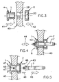
- Figure 2 in section a to be attached to the sleeve end cover; Figures 3, 4, 5 in section three different process steps during the production of a permanent electrical contact;
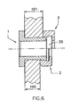
- Figure 6 in section two permanent electrical contacts which have been attached to a web of different thickness;
- Figures 7 and 8 in perspective, partially in section, two sides of a permanent electrical contact with cable lugs and electrical conductors.
In den Figuren 1 und 2 ist eine zylinderförmige Hülse sowie ein am freien Ende der Hülse angebrachter Deckel dargestellt.FIGS. 1 and 2 show a cylindrical sleeve and a cover attached to the free end of the sleeve.
Diese Teile sind gesamthaft mit 1 und 2 gekennzeichnet.These parts are labeled 1 and 2 in their entirety.
Die zylinderförmige Hülse 1 weist ein Zylinderstück 3 auf.The
An einem Ende weist die zylinderförmige Hülse 1 einen angeformten Flansch 4 auf, der als Anlageflansch und als elektrischer Kontakt ausgebildet ist.At one end, the
Die zylinderförmige Hülse 1 wird in Axialrichtung von einer Bohrung 102 durchdrungen.The
An der Außenseite weist der Flansch 4 eine leicht ballig ausgebildete Fläche 5 auf.On the outside, the
Der Flansch 4 der zylinderförmigen Hülse 1 weist eine Ausnehmung 6 auf, die geeignet ist, den Kopf eines Ziehwerkzeuges 7 aufzunehmen, mit dem der Ziehvorgang der zylinderförmigen Hülse 3 des Bauteiles 1 erfolgt (Figur 4).The
Das freie Ende der zylinderförmigen Hülse 3 weist ferner an seinem stirnseitigen Ende eine Ausnehmung 10 auf, die geeignet ist, dem während des Ziehvorganges entstehenden Materialwall aufzunehmen.The free end of the
Die Ausnehmung 10 hat in vorteilhafter Weise kegelstumpfartige Form.The
Der Abschlußdeckel 2 weist auf einer Seite eine ebene Fläche 15 auf, um eine elektrische Kontaktfläche zu schaffen.The
Die Bohrung 16 der Deckels 2 weist einen Durchmesser auf, der größer als der maximale Querschnitt des Ziehkopfes 7 ist. Der Deckel 2 weist ferner eine innenliegende Ausnehmung 20 auf.The
In vorteilhafter Weise ist die innenliegende Ausnehmung 20 konisch ausgebildet und wird von einer umlaufenden Wand begrenzt, die eine Hinterschneidung bildet.Advantageously, the
Der Eintritt 21 der Ausnehmung 20 weist einen Durchmesser 22 auf, der etwas größer als der Durchmesser 25 der zylinderförmigen Hülse 3 ist.The
In vorteilhafter Weise sind die Abmessungen 22 des Eintrittes 21 der innenliegenden Ausnehmung 20 übereinstimmend mit dem Durchmesser 27 der Bohrung 28 gewählt. In diese Bohrungen 28 wird die zylinderförmige Hülse 3 des Teiles 1 für die Herstellung eines permanenten, elektrischen Kontaktes am Steg eines Schienenstranges eingesetzt.Advantageously, the
In einer besonderen Ausführungsform der Erfindung weist die innenliegende Ausnehmung 20 eine umlaufende Wand 30 auf, die um ungefähr 10° gegenüber der Achse 31 der Deckel 2 geneigt ist.In a particular embodiment of the invention, the
Die innere Ausnehmung 20 weist eine Tiefe 32 auf, die ausreichend ist, um im Inneren der Deckel 2 eine Kammer 33 zu begrenzen. Die Kammer ist derartig ausgelegt, daß sie eine größtmögliche Materialmenge, die während des Ziehvorganges der zylinderförmigen Hülse 1 verdrängt wird, aufnehmen kann.The
Die zylinderförmige Hülse 1 besteht aus elektrisch leitendem Material, z.B. aus elektrolytischem Kupfer.The
Die Deckel 2 ist aus einem elektrisch leitendem Material hergestellt, daß mechanische Merkmale aufweist, die ausreichend sind, um die auftretenden Druckkräften während des Ziehvorganges aufzunehmen.The
Aus diesem Grunde ist die Deckel 2 in vorteilhafter Weise aus einer Kupferlegierung hergestellt, z.B. Kupfer, das mit Beryllium, Strontium, Zirkonium, Nickel-Silizium legiert wurde.For this reason, the
In vorteilhafter Weise ist die zylinderförmige Hülse 1 und die Deckel 2 unter Einsatz eines Materials hergestellt, das gleiche Wärmeausdehnungskoeffizienten aufweist.Advantageously, the
Auf diese Weise wird die zylinderförmige Hülse und die aufgesetzte Deckel aufgrund thermischer Veränderungen gleichmässig verformt werden, wodurch ein Ablösen zwischen der zylinderförmigen Hülse 1 und der Deckel 2 vermieden wird, und somit Verschlechterung des elektrischen Kontaktes sowie kein gegenseitiges Trennen der Bauteile eintritt.In this way, the cylindrical sleeve and the attached lid will be deformed uniformly due to thermal changes, whereby a separation between the
In einer weiteren Ausführungsform der Erfindung ist vorgesehen, daß die zylinderförmige Hülse 1 und die Deckel 2 mit einer Zinnschicht ummantelt werden.In a further embodiment of the invention it is provided that the
Die Vorsehung einer Zinnschicht verhindert einen unerwünschten Oxidationsvorgang an Teilen des elektrischen Kontaktes.The provision of a tin layer prevents unwanted oxidation of parts of the electrical contact.
Ferner wird durch die Vorsehung einer Zinnschicht eine mögliche Elektrolyse zwischen dem Kupfermaterial der zylinderförmigen Hülse sowie dem aufgesetzten Deckel und dem aus Stahl bestehenden Schienenkörper vermieden. Dies aufgrund der Tatsache, daß Zinn elektrolytisch in einer Zwischenposition zwischen diesen beiden Metallen liegt.Furthermore, the provision of a tin layer avoids possible electrolysis between the copper material of the cylindrical sleeve and the attached cover and the rail body made of steel. This is due to the fact that tin is electrolytic in one Intermediate position between these two metals.
Den Figuren 3, 4 und 5 können die wesentlichen Verfahrensschritte zur Herstellung eines doppelten, elektrischen, permanenten Kontaktes, der am Steg 40 eines Schienenkörpers 52 anzubringen ist, entnommen werden.Figures 3, 4 and 5, the essential process steps for producing a double, permanent electrical contact, which is to be attached to the
Der erste durchzuführende Verfahrensschritt besteht darin, daß der Steg 40 des Schienenkörpers mit einer durchgehenden Bohrung versehen wird. Dabei ist vorgesehen, daß der Durchmesser des Bohrwerkzeuges geringfügig größer als die Abmessungen 25 des Umfangsmantels 26 der zylinderförmigen Hülse 3 ist.The first step to be carried out is that the
Auf diese Weise kann die Bohrung 28 des Steges 40 des Schienenkörpers die zylinderförmige Hülse 3 frei aufnehmen.In this way, the
Um überprüfen zu können, ob die Bohrung 28 mit dem gewünschten Durchmesser 27 erstellt wurde, eröffnet sich die Möglichkeit, in die Bohrung 28 ein Mess- und Kontrollkaliber einzusetzen.To be able to check whether the
Dieses Kaliber weist geeigte Formgestaltung auf und wird zusammen mit der nicht dargestellten Montageeinrichtung geliefert.This caliber has sige design and is supplied together with the mounting device, not shown.
Für den Fall, daß die Durchgangsbohrung 28 bereits zu einem früheren Zeitpunkt hergestellt wurde, ist es notwendig zu gewährleisten, daß die Wandfläche der Bohrung 28 frei von Schmutzablagerungen ist, welche die Qualität des herzustellenden elektrischen Kontaktes beeinflussen könnten.In the event that the through-
Aus diesem Grunde ist es erforderlich, die Fläche einer bereits bestehenden Bohrung 28 einer Nachbearbeitung zu unterziehen.For this reason, it is necessary to subject the surface of an existing
Ist die Bohrung 28 im Steg 40 des Schienenkörpers fertiggestellt, wird es möglich sein, in Richtung des Pfeiles 41 eine zylindrische Hülse 1 in die Bohrung einzusetzen, wobei der Flansch 4 mit der Seitenfläche des Steges 40 des Schienenkörpers in Anlage gebracht wird.If the
Anschließend ist es möglich, in die Durchgangsbohrung 102 der zylinderförmigen Hülse das kalibrierte Kopfstück 7 des Ziehwerkzeuges einzusetzen.Subsequently, it is possible to insert into the through-
Das kalibrierte Kopfstück 7 des Ziehwerkzeuges wird in die Durchgangsbohrung 102 der zylinderförmigen Hülse 1 von der Seite des Anlageflansches 4 eingesetzt.The calibrated head 7 of the pulling tool is inserted into the through
Dabei wird das kegelstumpfförmig ausgebildete Teil 43 des kalibrierten Ziehkopfes 7 (in Richtung des Pfeiles 44) in die innere Ausnehmung 6 der zylinderförmigen Hülse 1 eingesetzt.In this case, the frustoconically formed
In vorteilhafter Weise wurde in die Ausnehmung 6 vor Einbringen des Ziehwerkzeuges ein Gleitmittel eingebracht.Advantageously, a lubricant was introduced into the
Eine Verlängerung des kalibrierten Kopfes des Ziehwerkzeuges 7 tritt nach Einsetzen in die Durchgangsbohrung 102 der Hülse 1 auf der dem Flasch 4 gegenüberliegenden Seite der Hülse aus dieser aus.An extension of the calibrated head of the drawing tool 7 occurs after insertion into the through
Anschließend erfolgt ein Aufsetzen der Deckel 2 in Übereinstimmung mit dem freien Ende der zylinderförmigen Hülse 3, das aus der Bohrung 28 des Steges 40 des Schienenkörpers 52 austritt.Subsequently, a placement of the
Die innenliegende Ausnehmung 20 der Deckel 2 ist dabei auf den Steg 40 des Schienenkörpers gerichtet (Pfeil 42).The
Auf diese Weise erfolgt ein Zentrieren der Deckel 2 gegenüber der Bohrung 28 im Steg 40 des Schienenkörpers und somit gegenüber dem Schaft 3 der zylinderförmigen Hülse 1.In this way, the
Es ist nun möglich, das freie Ende des Schaftes des kalibrierten Ziehkopfes 7, der aus der Deckel 2 herausragt, mit einer Ziehvorrichtung (nicht dargestellt) zu verbinden.It is now possible to connect the free end of the shaft of the calibrated pulling head 7, which protrudes from the
Bei Durchführung des Ziehvorganges (in Richtung des Pfeiles 45) wird durch den kalibrierten Ziehkopf 7 ein Ziehvorgang in Richtung der Deckel 2 vorgenommen, und es tritt eine Materialverdrängung ein, die zu einem Verschieben des Materials führt, das die Durchgangsbohrung 102 begrenzt.When performing the drawing operation (in the direction of arrow 45), a drawing operation in the direction of the
Dem Ziehvorgang wird in geeigneter Weise über die Ziehvorrichtung entgegengewirkt, da diese die auftretenden Kräfte auf die ebene Fläche 15 der Deckel 2 überträgt (Pfeil 46).The drawing operation is counteracted in a suitable manner via the pulling device, since this transfers the forces occurring on the
Die Deckel 2 wird in Anlage mit dem Steg 40 des Schienenkörpers gehalten. Das konische Teilstück 43 des Ziehkopfes 7 bringt während des Expansionsziehvorganges der Hülse 1 derenn äußeren Mantel 26 in kraftschlüssige Verbindung mit der Wandung der Bohrung 28, wodurch ein hervorrangender, dauerhafter, elektrischer Kontakt geschaffen wird.The
Die durch den Kopf 43 des Ziehwerkzeuges hervorgerufene Krafteinwirkung verformt die anfangs ballig ausgebildete Oberfläche 5 des Flansches 4 der zylinderförmigen Hülse 1 in eine ebene Fläche (Pfeil 47).The force caused by the
Das verdrängte Material der zylinderförmigen Hülse 3 häuft sich wallartig während des Ziehvorganges an und wird in der Kammer 33, die von der Ausnehmung 20 der Deckel 2 gebildet ist, (Pfeil 48) aufgenommen.The displaced material of the
Beim Durchlauf des kalibrierten Ziehkopfes 7 durch die Hülse 3 strömt das angehäufte Material zur Wand 30 der Deckel 2 und erzeugt somit den gewünschten elektrischen Kontakt zwischen Hülse 1 der Deckel 2 und bildet gleichzeitig eine kraftschlüssige und auch formschlüssige Verbindung zwischen Deckel 2 und dem Ende der Hülse 1.When passing the calibrated pulling head 7 through the
Während des Ziehvorganges wird das freie Ende des Schaftes 3, dank der Vorsehung einer kegelförmig ausgebildeten Ausnehmung 10, derartig verformt, daß der kopfseitige Rand eben bleibt. Auf diese Weise wird vermieden, daß das verdrängte Material, das aus der Bohrung 28 austritt, über die Bohrung 16 aus der Deckel austritt und ein Hindernis für die einwandfreie Montage eines Kabelschuhes an der Fläche 15 der Deckel 2 bilden könnteDuring the drawing process, the free end of the
Der Figur 6 kann entnommen werden, daß in vorteilhafter Weise, unter Verwendung eines elektrischen Kontaktes, eine Anordnung an Stegen von Schienenkörpern mit unterschiedlicher Dicke 100, 101 möglich wird.From Figure 6 it can be seen that, advantageously, using an electrical contact, a Arrangement on webs of rail bodies with
Besonders der Figur 6 kann entnommen werden, daß dank des vorgesehenen Volumens der Kammmer 33, die durch die innere Ausnehmung 20 festgelegt wird, die Möglichkeit besteht, unterschiedliche Materialmengen des verdrängten Materials während des Ziehvorganges, in Abhängigkeit von unterschiedlichen Längen 100, 101 der Bohrung 28, im Steg 40 des Schienenkörpers 52 aufzunehmen.It can be seen in particular from FIG. 6 that thanks to the intended volume of the
Der Figur 7 und 8 kann entnommen werden, wie zwei elektrische Leiter 50 mit ihren Anschlußschuhen 51 zu beiden Seiten des Steges 40 des Schienenkörpers 52, unter Verwendung einer einzigen Hülse 1, montiert-werden.From Figures 7 and 8 it can be seen how two
Sobald der Kabelschuh 53 des Kabelendes 51 an der ebenen Fläche 15 des elektrischen Kontaktes auf der Seite der Deckel 2 sowie auf der Fläche 4 des Flansches 4 der zylinderförmigen Hülse 1 angeordnet sind, werden beide Kabelschuhe unter Verwendung einer einzigen Schraube 55 montiert und fest verspannt.Once the
Claims (13)
- Method for establishing a permanent electrical contact on the web (40) of a rail body (52) by implementing a drawing operation, a through-hole (28) being introduced into the web (40) of the rail body (52), and a cylindrical sleeve (3) being inserted into this through-hole (28), said cylindrical sleeve (3) having a through-hole (102) and having a bearing flange (4) at one end which is brought to bear with one side of the web (40) of the rail body (52), characterized in that a cover (2) is placed on the free end of the cylindrical sleeve (3), which passes through the rail web, said cover (2) surrounding the end of the sleeve (3) with an inner cutout (20), and in that the through-hole (102) is subjected to a drawing operation, and the displaced material is introduced into the inner cutout (20) of the cover (2) and is brought to bear in a force-fitting and interlocking manner against the walls (30) of the cutout (20).
- Permanent electrical contact on the web (40) of a rail body (52), the contact being subjected to a drawing operation, and the web (40) of the rail body (52) having a through-hole (28) for the purpose of accommodating a cylindrical sleeve (3), which is provided with a through-hole (102) and has a bearing flange (4) at one end, said bearing flange (4) bearing against one side of the web (40) of the rail body (52), characterized in that a cover (2), which surrounds the free end of the cylindrical sleeve (3) and has a planar contact surface (15) on its outer side, is arranged on that side of the rail web (40) which lies opposite the bearing flange (4), in that the cover (2) has an inner cutout (20) on its side directed towards the web (40), said cutout (20) surrounding the free end of the cylindrical sleeve (3), and the material displaced during the drawing operation of the through-hole (102) is introduced into the inner cutout (20) of the cover (2) and this material bears in a force-fitting and interlocking manner against the walls of the cutout (20).
- Electrical contact according to Patent Claim 2, characterized in that the cutout (20) of the cover (2) has a conical shape.
- Electrical contact according to Patent Claim 3, characterized in that the material displaced out of the through-hole (102) of the sleeve (3) comes to bear against the wall (30), which forms an undercut, of the cutout (20).
- Electrical contact according to Patent Claim 2, characterized in that the free end of the cylindrical sleeve (3) has a cutout (10) in the form of a truncated cone at its head.
- Electrical contact according to Patent Claim 2, characterized in that the cover (2) has a hole (16) which has a greater diameter than the head of the drawing die (7).
- Electrical contact according to Patent Claim 2, characterized in that the entrance (21) of the cutout (20) of the cover (2) has a dimension (22) which corresponds to the diameter (27) of the hole (28) in the web (40).
- Electrical contact according to Patent Claim 3, characterized in that the inner cutout (20) of the cover (2) has a wall (3), which delimits an undercut, and the wall (30) is arranged at an angle of 10° with respect to the axis (31) of the cover (2).
- Electrical contact according to Patent Claim 2, characterized in that the cover (2) is made from a copper alloy having a high electrical conductivity.
- Electrical contact according to Patent Claim 2, characterized in that the cover (2) is made from a copper alloy having increased mechanical strength.
- Electrical contact according to Patent Claim 2, characterized in that the cover (2) and the cylindrical sleeve (1) are made from a material which has the same coefficient of thermal expansion.
- Electrical contact according to Patent Claim 2, characterized in that the cylindrical sleeve (1) and the cover (2) are coated with a tin layer.
- Electrical contact according to Patent Claim 2, characterized in that the cylindrical sleeve (1), which is connected to the cover (2) and the web (40) of the rail body (52), accommodates a screw (55), and the screw (55) accommodates the conductors (50) provided with connection shoes (51), and these connection shoes are pressed against the surface (5) of the flange (4) of the sleeve (1) and against the planar surface (15) of the cover (2) using screw connections (55).
Priority Applications (4)
| Application Number | Priority Date | Filing Date | Title |
|---|---|---|---|
| AT98105145T ATE315838T1 (en) | 1998-03-22 | 1998-03-22 | METHOD FOR PRODUCING A PERMANENT ELECTRICAL CONTACT ON THE WEB OF A RAILWAY RAIL AND PERMANENT ELECTRICAL CONTACT PRODUCED USING THE METHOD |
| ES98105145T ES2256901T3 (en) | 1998-03-22 | 1998-03-22 | PROCEDURE FOR ESTABLISHING A PERMANENT ELECTRICAL CONTACT IN THE SOUL OF A RAIL RAIL AND PERMANENT ELECTRICAL CONTACT OBTAINED WITH SUCH PROCEDURE. |
| DE59813339T DE59813339D1 (en) | 1998-03-22 | 1998-03-22 | Method for producing a permanent electrical contact on the web of a railroad track and an electrical permanent contact produced by the method |
| EP98105145A EP0945919B1 (en) | 1998-03-22 | 1998-03-22 | Method for establishing a permanent electric contact to the web of rails and the corresponding contact |
Applications Claiming Priority (1)
| Application Number | Priority Date | Filing Date | Title |
|---|---|---|---|
| EP98105145A EP0945919B1 (en) | 1998-03-22 | 1998-03-22 | Method for establishing a permanent electric contact to the web of rails and the corresponding contact |
Publications (2)
| Publication Number | Publication Date |
|---|---|
| EP0945919A1 EP0945919A1 (en) | 1999-09-29 |
| EP0945919B1 true EP0945919B1 (en) | 2006-01-11 |
Family
ID=8231632
Family Applications (1)
| Application Number | Title | Priority Date | Filing Date |
|---|---|---|---|
| EP98105145A Expired - Lifetime EP0945919B1 (en) | 1998-03-22 | 1998-03-22 | Method for establishing a permanent electric contact to the web of rails and the corresponding contact |
Country Status (4)
| Country | Link |
|---|---|
| EP (1) | EP0945919B1 (en) |
| AT (1) | ATE315838T1 (en) |
| DE (1) | DE59813339D1 (en) |
| ES (1) | ES2256901T3 (en) |
Cited By (14)
| Publication number | Priority date | Publication date | Assignee | Title |
|---|---|---|---|---|
| US7926319B2 (en) | 2005-12-28 | 2011-04-19 | Fatigue Technology, Inc. | Mandrel assembly and method of using the same |
| US7926318B2 (en) | 2006-04-27 | 2011-04-19 | Fatigue Technology, Inc. | Alignment device and methods of using the same |
| US7946628B2 (en) | 2003-07-31 | 2011-05-24 | Fatigue Technology, Inc. | Tubular metal fitting expandable in a wall opening and method of installation |
| US7958766B2 (en) | 2006-06-29 | 2011-06-14 | Fatigue Technology, Inc. | Self-aligning tools and a mandrel with retention sleeve |
| US8069699B2 (en) | 2006-08-28 | 2011-12-06 | Fatigue Technology, Inc. | Installation/processing systems and methods of using the same |
| US8128308B2 (en) | 2000-06-26 | 2012-03-06 | Fatigue Technology Inc. | Double flanged bushings and installation methods |
| US8312606B2 (en) | 2007-10-16 | 2012-11-20 | Fatigue Technology, Inc. | Expandable fastener assembly with deformed collar |
| US8506222B2 (en) | 2008-07-18 | 2013-08-13 | Fatigue Technology, Inc. | Nut plate assembly and methods of using the same |
| US8568034B2 (en) | 2006-01-11 | 2013-10-29 | Fatigue Technology, Inc. | Bushing kits, bearings, and methods of installation |
| US8636455B2 (en) | 2009-04-10 | 2014-01-28 | Fatigue Technoloy, Inc. | Installable assembly having an expandable outer member and a fastener with a mandrel |
| US8647035B2 (en) | 2009-12-16 | 2014-02-11 | Fatigue Technology, Inc. | Modular nut plate assemblies and methods of using the same |
| US8763229B2 (en) | 2011-06-03 | 2014-07-01 | Fatigue Technology, Inc. | Expandable crack inhibitor method |
| US8938886B2 (en) | 2012-01-30 | 2015-01-27 | Fatigue Technology, Inc. | Smart installation/processing systems, components, and methods of operating the same |
| US9114449B2 (en) | 2011-06-15 | 2015-08-25 | Fatigue Technology, Inc. | Modular nut plates with closed nut assemblies |
Families Citing this family (11)
| Publication number | Priority date | Publication date | Assignee | Title |
|---|---|---|---|---|
| SE527876C2 (en) * | 2004-11-26 | 2006-07-04 | Safetrack Infrasystems Sisab A | Method and apparatus for connecting an electrical conductor to a metal rail and tools for attaching a bushing to a hole in a metal rail |
| US20070110541A1 (en) * | 2005-10-28 | 2007-05-17 | Fatigue Technology, Inc. | Radially displaceable bushing for retaining a member relative to a structural workpiece |
| JP5204096B2 (en) | 2006-04-27 | 2013-06-05 | ファティーグ テクノロジー インコーポレイテッド | Wave relaxation geometry in a structural member that is radially expandable into the workpiece |
| FR2922370B1 (en) * | 2007-10-15 | 2009-11-20 | Eldre | ELECTRICAL CONNECTION TERMINAL. |
| WO2009111745A2 (en) | 2008-03-07 | 2009-09-11 | Fatigue Technology, Inc. | Expandable member with wave inhibitor and methods of using the same |
| US8851395B2 (en) | 2009-12-18 | 2014-10-07 | Cembre Ltd. | Method for the application of a permanent electrical contact to the web of rails |
| IT1398327B1 (en) * | 2010-02-26 | 2013-02-22 | Cembre Spa | SHOOTING DEVICE TO PULL A PUNCH THROUGH A CONTACT COMPASS |
| EP2789053A4 (en) * | 2011-12-07 | 2015-08-12 | Eldre Corp | Bus bar releasable bushing apparatus |
| ITMI20120406A1 (en) | 2012-03-15 | 2013-09-16 | Cembre Spa | PERMANENT ELECTRICAL CONTACT THAT CAN BE APPLIED ON THE SOUND OF RAILS AND THE LIKE |
| CN109131438A (en) * | 2018-08-27 | 2019-01-04 | 深圳市森博尔电力设备科技有限公司 | A kind of railroad track return-flow system |
| CN109722950A (en) * | 2019-01-14 | 2019-05-07 | 上海国爱电气有限公司 | A kind of dedicated 35 ° of corner terminals of the equal return cable of stray electrical current |
Family Cites Families (2)
| Publication number | Priority date | Publication date | Assignee | Title |
|---|---|---|---|---|
| IT1215911B (en) * | 1988-02-18 | 1990-02-22 | Cembre Srl | PERMANENT ELECTRIC CONTACT APPLICABLE TO THE SOUL OF SIMILAR RAILS. |
| DE29712206U1 (en) * | 1997-07-11 | 1997-08-28 | Kabelkonfektionstechnik Kkt Gm | Device for connecting an electrical line to a railroad track or the like. |
-
1998
- 1998-03-22 AT AT98105145T patent/ATE315838T1/en active
- 1998-03-22 ES ES98105145T patent/ES2256901T3/en not_active Expired - Lifetime
- 1998-03-22 DE DE59813339T patent/DE59813339D1/en not_active Expired - Lifetime
- 1998-03-22 EP EP98105145A patent/EP0945919B1/en not_active Expired - Lifetime
Cited By (22)
| Publication number | Priority date | Publication date | Assignee | Title |
|---|---|---|---|---|
| US8128308B2 (en) | 2000-06-26 | 2012-03-06 | Fatigue Technology Inc. | Double flanged bushings and installation methods |
| US7946628B2 (en) | 2003-07-31 | 2011-05-24 | Fatigue Technology, Inc. | Tubular metal fitting expandable in a wall opening and method of installation |
| US7926319B2 (en) | 2005-12-28 | 2011-04-19 | Fatigue Technology, Inc. | Mandrel assembly and method of using the same |
| US8353193B2 (en) | 2005-12-28 | 2013-01-15 | Fatigue Technology, Inc. | Mandrel assembly and method of using the same |
| US8568034B2 (en) | 2006-01-11 | 2013-10-29 | Fatigue Technology, Inc. | Bushing kits, bearings, and methods of installation |
| US8387436B2 (en) | 2006-04-27 | 2013-03-05 | Fatigue Technology, Inc. | Alignment device and methods of using the same |
| US7926318B2 (en) | 2006-04-27 | 2011-04-19 | Fatigue Technology, Inc. | Alignment device and methods of using the same |
| US8191395B2 (en) | 2006-04-27 | 2012-06-05 | Fatigue Technology, Inc. | Alignment device and methods of using the same |
| US7958766B2 (en) | 2006-06-29 | 2011-06-14 | Fatigue Technology, Inc. | Self-aligning tools and a mandrel with retention sleeve |
| US8061178B2 (en) | 2006-06-29 | 2011-11-22 | Fatigue Technology, Inc. | Self-aligning tools and seating assemblies |
| US8117885B2 (en) | 2006-06-29 | 2012-02-21 | Fatigue Technology, Inc. | Mandrel with retention sleeve and methods of using the same |
| US8069699B2 (en) | 2006-08-28 | 2011-12-06 | Fatigue Technology, Inc. | Installation/processing systems and methods of using the same |
| US8402806B2 (en) | 2006-08-28 | 2013-03-26 | Fatigue Technology, Inc. | Installation/processing systems and methods of using the same |
| US8312606B2 (en) | 2007-10-16 | 2012-11-20 | Fatigue Technology, Inc. | Expandable fastener assembly with deformed collar |
| US8506222B2 (en) | 2008-07-18 | 2013-08-13 | Fatigue Technology, Inc. | Nut plate assembly and methods of using the same |
| US8636455B2 (en) | 2009-04-10 | 2014-01-28 | Fatigue Technoloy, Inc. | Installable assembly having an expandable outer member and a fastener with a mandrel |
| US8647035B2 (en) | 2009-12-16 | 2014-02-11 | Fatigue Technology, Inc. | Modular nut plate assemblies and methods of using the same |
| US8763229B2 (en) | 2011-06-03 | 2014-07-01 | Fatigue Technology, Inc. | Expandable crack inhibitor method |
| US9114449B2 (en) | 2011-06-15 | 2015-08-25 | Fatigue Technology, Inc. | Modular nut plates with closed nut assemblies |
| US8938886B2 (en) | 2012-01-30 | 2015-01-27 | Fatigue Technology, Inc. | Smart installation/processing systems, components, and methods of operating the same |
| US10130985B2 (en) | 2012-01-30 | 2018-11-20 | Fatigue Technology, Inc. | Smart installation/processing systems, components, and methods of operating the same |
| US10843250B2 (en) | 2012-01-30 | 2020-11-24 | Fatigue Technology, Inc. | Smart installation/processing systems, components, and methods of operating the same |
Also Published As
| Publication number | Publication date |
|---|---|
| EP0945919A1 (en) | 1999-09-29 |
| ATE315838T1 (en) | 2006-02-15 |
| DE59813339D1 (en) | 2006-04-06 |
| ES2256901T3 (en) | 2006-07-16 |
Similar Documents
| Publication | Publication Date | Title |
|---|---|---|
| EP0945919B1 (en) | Method for establishing a permanent electric contact to the web of rails and the corresponding contact | |
| DE102016105768B3 (en) | Electric conductor with a friction welding sleeve | |
| EP2301115B1 (en) | Electrical connection device | |
| EP3189561B1 (en) | Crimp contact | |
| DE10259803B3 (en) | Electrical termination connection for outer conductor of coaxial cable has plug part with 2 plug sections fitting into housing wall opening with 2 reception sections | |
| EP1524731B1 (en) | Plug casing with improved cable sealing | |
| DE3912139C2 (en) | Process for overmolding the junction of two electrical lines | |
| DE102017123864B3 (en) | Electric line arrangement with direct contacting and method for its production | |
| DE102013013368B4 (en) | Method for establishing an electrical connection and electrical connection | |
| DE202005021422U1 (en) | Cable connector of a connector device for medium and high voltage engineering | |
| DE4340411A1 (en) | Cable connector | |
| DE102020106415B4 (en) | FRICTION WELDING CONNECTOR AND METHOD FOR MANUFACTURING THEREOF | |
| DE102022003696A1 (en) | METHOD OF MAKING AN ASSEMBLED STATE OF AN ASSEMBLY AND ASSEMBLY | |
| DE19704824A1 (en) | Method for connecting pipes of deformable material e.g. metal pipes | |
| EP3736920B1 (en) | Contact terminal and method of manufacturing same | |
| DE102012221466A1 (en) | Component assembly between two parts of the current-carrying components and method for producing a composite component | |
| EP0203253A2 (en) | Encapsulated non-disconnectable electrical conductor connection | |
| WO2018162629A1 (en) | Method for connecting a sandwich component | |
| DE102019116127B4 (en) | Sliding contact and method for manufacturing a sliding contact | |
| WO2002097928A1 (en) | Cable connecting device | |
| EP4002592A1 (en) | Connector for electrical line and line connection | |
| DE102016120087A1 (en) | Connecting element for fastening a metal part to a printed circuit board | |
| DE102018115122B4 (en) | Contact pin sealing with thermoplastic elastomer | |
| DE102013022354B3 (en) | Method for establishing an electrical connection and electrical connection | |
| DE3531038A1 (en) | Plug for a coaxial cable |
Legal Events
| Date | Code | Title | Description |
|---|---|---|---|
| PUAI | Public reference made under article 153(3) epc to a published international application that has entered the european phase |
Free format text: ORIGINAL CODE: 0009012 |
|
| AK | Designated contracting states |
Kind code of ref document: A1 Designated state(s): AT BE CH DE DK ES FR GB IT LI NL PT SE |
|
| AX | Request for extension of the european patent |
Free format text: AL;LT;LV;MK;RO;SI |
|
| RTI1 | Title (correction) |
Free format text: METHOD FOR ESTABLISHING A PERMANENT ELECTRIC CONTACT TO THE WEB OF RAILS AND THE CORRESPONDING CONTACT |
|
| 17P | Request for examination filed |
Effective date: 19991115 |
|
| AKX | Designation fees paid |
Free format text: AT BE CH DE DK ES FR GB IT LI NL PT SE |
|
| GRAP | Despatch of communication of intention to grant a patent |
Free format text: ORIGINAL CODE: EPIDOSNIGR1 |
|
| GRAS | Grant fee paid |
Free format text: ORIGINAL CODE: EPIDOSNIGR3 |
|
| GRAA | (expected) grant |
Free format text: ORIGINAL CODE: 0009210 |
|
| AK | Designated contracting states |
Kind code of ref document: B1 Designated state(s): AT BE CH DE DK ES FR GB IT LI NL PT SE |
|
| REG | Reference to a national code |
Ref country code: CH Ref legal event code: EP |
|
| REF | Corresponds to: |
Ref document number: 59813339 Country of ref document: DE Date of ref document: 20060406 Kind code of ref document: P |
|
| PG25 | Lapsed in a contracting state [announced via postgrant information from national office to epo] |
Ref country code: DK Free format text: LAPSE BECAUSE OF FAILURE TO SUBMIT A TRANSLATION OF THE DESCRIPTION OR TO PAY THE FEE WITHIN THE PRESCRIBED TIME-LIMIT Effective date: 20060411 |
|
| REG | Reference to a national code |
Ref country code: CH Ref legal event code: NV Representative=s name: FREI PATENTANWALTSBUERO |
|
| REG | Reference to a national code |
Ref country code: SE Ref legal event code: TRGR |
|
| GBT | Gb: translation of ep patent filed (gb section 77(6)(a)/1977) |
Effective date: 20060420 |
|
| PG25 | Lapsed in a contracting state [announced via postgrant information from national office to epo] |
Ref country code: PT Free format text: LAPSE BECAUSE OF FAILURE TO SUBMIT A TRANSLATION OF THE DESCRIPTION OR TO PAY THE FEE WITHIN THE PRESCRIBED TIME-LIMIT Effective date: 20060612 |
|
| REG | Reference to a national code |
Ref country code: ES Ref legal event code: FG2A Ref document number: 2256901 Country of ref document: ES Kind code of ref document: T3 |
|
| ET | Fr: translation filed | ||
| PLBE | No opposition filed within time limit |
Free format text: ORIGINAL CODE: 0009261 |
|
| STAA | Information on the status of an ep patent application or granted ep patent |
Free format text: STATUS: NO OPPOSITION FILED WITHIN TIME LIMIT |
|
| 26N | No opposition filed |
Effective date: 20061012 |
|
| REG | Reference to a national code |
Ref country code: FR Ref legal event code: PLFP Year of fee payment: 19 |
|
| REG | Reference to a national code |
Ref country code: FR Ref legal event code: PLFP Year of fee payment: 20 |
|
| PGFP | Annual fee paid to national office [announced via postgrant information from national office to epo] |
Ref country code: SE Payment date: 20170323 Year of fee payment: 20 Ref country code: FR Payment date: 20170323 Year of fee payment: 20 Ref country code: CH Payment date: 20170323 Year of fee payment: 20 Ref country code: NL Payment date: 20170323 Year of fee payment: 20 |
|
| PGFP | Annual fee paid to national office [announced via postgrant information from national office to epo] |
Ref country code: BE Payment date: 20170220 Year of fee payment: 20 Ref country code: AT Payment date: 20170330 Year of fee payment: 20 Ref country code: GB Payment date: 20170323 Year of fee payment: 20 |
|
| PGFP | Annual fee paid to national office [announced via postgrant information from national office to epo] |
Ref country code: IT Payment date: 20170130 Year of fee payment: 20 |
|
| PGFP | Annual fee paid to national office [announced via postgrant information from national office to epo] |
Ref country code: DE Payment date: 20170403 Year of fee payment: 20 |
|
| PGFP | Annual fee paid to national office [announced via postgrant information from national office to epo] |
Ref country code: ES Payment date: 20170328 Year of fee payment: 20 |
|
| REG | Reference to a national code |
Ref country code: NL Ref legal event code: MK Effective date: 20180321 |
|
| REG | Reference to a national code |
Ref country code: DE Ref legal event code: R071 Ref document number: 59813339 Country of ref document: DE |
|
| REG | Reference to a national code |
Ref country code: CH Ref legal event code: PL |
|
| REG | Reference to a national code |
Ref country code: BE Ref legal event code: MK Effective date: 20180322 |
|
| REG | Reference to a national code |
Ref country code: GB Ref legal event code: PE20 Expiry date: 20180321 |
|
| PG25 | Lapsed in a contracting state [announced via postgrant information from national office to epo] |
Ref country code: GB Free format text: LAPSE BECAUSE OF EXPIRATION OF PROTECTION Effective date: 20180321 |
|
| REG | Reference to a national code |
Ref country code: SE Ref legal event code: EUG |
|
| REG | Reference to a national code |
Ref country code: AT Ref legal event code: MK07 Ref document number: 315838 Country of ref document: AT Kind code of ref document: T Effective date: 20180322 |
|
| REG | Reference to a national code |
Ref country code: ES Ref legal event code: FD2A Effective date: 20200721 |
|
| PG25 | Lapsed in a contracting state [announced via postgrant information from national office to epo] |
Ref country code: ES Free format text: LAPSE BECAUSE OF EXPIRATION OF PROTECTION Effective date: 20180323 |