EP0945358B1 - Net-like cover or sheath made from plastic material and process for manufacturing same - Google Patents
Net-like cover or sheath made from plastic material and process for manufacturing same Download PDFInfo
- Publication number
- EP0945358B1 EP0945358B1 EP99104537A EP99104537A EP0945358B1 EP 0945358 B1 EP0945358 B1 EP 0945358B1 EP 99104537 A EP99104537 A EP 99104537A EP 99104537 A EP99104537 A EP 99104537A EP 0945358 B1 EP0945358 B1 EP 0945358B1
- Authority
- EP
- European Patent Office
- Prior art keywords
- mesh structure
- marking surface
- strands
- marking
- information
- Prior art date
- Legal status (The legal status is an assumption and is not a legal conclusion. Google has not performed a legal analysis and makes no representation as to the accuracy of the status listed.)
- Expired - Lifetime
Links
Images

Classifications
-
- D—TEXTILES; PAPER
- D06—TREATMENT OF TEXTILES OR THE LIKE; LAUNDERING; FLEXIBLE MATERIALS NOT OTHERWISE PROVIDED FOR
- D06C—FINISHING, DRESSING, TENTERING OR STRETCHING TEXTILE FABRICS
- D06C23/00—Making patterns or designs on fabrics
- D06C23/04—Making patterns or designs on fabrics by shrinking, embossing, moiréing, or crêping
-
- B—PERFORMING OPERATIONS; TRANSPORTING
- B65—CONVEYING; PACKING; STORING; HANDLING THIN OR FILAMENTARY MATERIAL
- B65D—CONTAINERS FOR STORAGE OR TRANSPORT OF ARTICLES OR MATERIALS, e.g. BAGS, BARRELS, BOTTLES, BOXES, CANS, CARTONS, CRATES, DRUMS, JARS, TANKS, HOPPERS, FORWARDING CONTAINERS; ACCESSORIES, CLOSURES, OR FITTINGS THEREFOR; PACKAGING ELEMENTS; PACKAGES
- B65D29/00—Sacks or like containers made of fabrics; Flexible containers of open-work, e.g. net-like construction
- B65D29/04—Net-like containers made of plastics material
-
- B—PERFORMING OPERATIONS; TRANSPORTING
- B65—CONVEYING; PACKING; STORING; HANDLING THIN OR FILAMENTARY MATERIAL
- B65D—CONTAINERS FOR STORAGE OR TRANSPORT OF ARTICLES OR MATERIALS, e.g. BAGS, BARRELS, BOTTLES, BOXES, CANS, CARTONS, CRATES, DRUMS, JARS, TANKS, HOPPERS, FORWARDING CONTAINERS; ACCESSORIES, CLOSURES, OR FITTINGS THEREFOR; PACKAGING ELEMENTS; PACKAGES
- B65D65/00—Wrappers or flexible covers; Packaging materials of special type or form
- B65D65/02—Wrappers or flexible covers
- B65D65/22—Details
Definitions
- the invention relates to a blanket or envelope made of a plastic material according to the Preamble of claim 1 and a method for producing a blanket or Cover according to the preamble of claim 8.
- blankets or covers made of plastic material Use are each provided as intermediate layers or as a covering and consist in particular of a latticework made by extrusion, which consists of two crossed arrangements of transversely spaced strands is formed, the strands at the intersection of the two arrangements run perpendicular or at an angle to the strands of the other arrangement.
- the strands come to lie on two levels, such that in each level the strands are aligned parallel to each other.
- a tubular structure is known that is used for the production of bags or sacks for packaging purposes.
- the tubular structure has closed areas and areas with a network structure. Both Areas are already produced during extrusion.
- FR-A-1 210 534 is about woven tapes or fabrics after weaving treated with pressure and heat to change their structure. It can be too a fusion of the threads and optionally a layer of compact structure without the addition of additional material. This leaves woven ribbons and fabrics in the relatively small spaces easily form between the threads.
- the invention has for its object to provide a blanket or envelope whose Network structure is designed so that it is essentially a continuous one Lets form surface. Furthermore, the object of the invention is to provide a corresponding one Creating procedures.
- a blanket or cover for solving this problem has the features of claim 1 on.
- the surface is therefore an integral part of the network structure, in this Area the original network structure was removed and instead an essentially continuous area is available.
- Identification surface Information, information or the like can be placed on the surface for example to identify or explain the protective cover covered parts are applied. It is possible to apply a sticker that Printing the surface, embossing it, inserting characters into the surface (also as a recess), etc.
- the surface can also be used as a base or serve to hold objects. Connecting additional Information carrier with the protective blanket, for example attaching a trailer with appropriate information, is unnecessary.
- a method for solving the problem has the measures of claim 8.
- By the deformation of the network structure creates at least one surface. This area will formed by the original network structure in the area of the or each surface canceled and instead a substantially continuous surface is formed.
- the material forming the network structure is preferably so warmed up or compressed until a continuous Surface is formed.
- continuous area does not mean that a completely smooth and homogeneous Surface structure must arise. It is important that the formed area as a basis or documents for information, characters or to be applied or to be introduced Objects are sufficient. Unless it is the purpose of the area corresponds, a sticker on it should be strong enough can be liable. This can also be the case if the in the Breakthroughs in the network structure are not complete are closed.
- the molded surface preferably has a clear lower height or strength than the rest of the network structure.
- the latter has a height corresponding to the two superimposed layers. In contrast is the area due to the fact that it is pushed into the gaps in the network structure Material much thinner.
- the surface can be flat or deformed be or have deformations.
- the invention is also applicable to those formed from a network structure Cases or bags, for example to protect rotationally symmetrical or rod-shaped objects, such as Waves, cones or the like.
- Such covers can also on a pin that serves as a base to form the License plate area with a corresponding contours Stamps are applied.
- An approximately rectangular ceiling 10 is used for covering and Protection of goods to be transported in containers or on pallets mechanical components.
- the blanket 10 is on a layer of components placed in a container before one additional layer of components is filled.
- the blanket 10 is preferably made of thermoplastic Plastic, namely from two in the area of intersection points 11 interconnected layers 12, 13, each consisting of parallel plastic strands 14, 15. These are formed by extrusion and adhere to the area Crossing points 11 on the strands of the other layer.
- a marking area 16 In the ceiling 10 is a marking area 16 or as The surface or support provided is incorporated. This is almost circular in the present case, but can be have any shape.
- the marking area 16 is formed by a heated one Round stamp 17, the light pressure on the ceiling 10 as long is positioned until the through the plastic strands 14, 15th formed network structure largely dissolved and the above Marking area 16 has arisen.
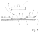
- the stamp 17 works with a base 19 as a counter tool together. This corresponds to the stamp trained, without recesses, recesses or the like. This closes a bottom 20 of the resulting compressed portion 21 of the marking area 16 approximately flush with the lower layer 13. In contrast, is a Top side 22 of section 21 opposite top layer 12 shifted inwards. Depending on the mesh size of the network structure there is also a paragraph 23 towards the bottom 20 and set as the peripheral edge of the compressed section 21.
- a stamp surface 24 is preferably flat, as well the resulting surface 16. Other shapes, such as recesses, Indentations and protrusions are possible.
- the heat and pressure of the stamp depend on the material of the Blanket 10 and of the desired density or the desired Structure of the marking area 16.
- a thermoplastic can on melted easily and in a short time and from one Network structure transformed into a continuous marking area become.
- a particular advantage of this process lies in that no material has to be added. It takes place just reshaping the existing material.
- the marking area 16 is in a separate operation or during the transformation of the network structure with a Provide a label, for example with information about the components to be protected by the ceiling 10.
- the stamp 17th can, for example, the desired information during the Emboss the forming process into the marking area 16.
- 1 and 2 is the application of specifying a Identification number shown.
- the labeling is preferably on the inward offset Top 22. This provides additional protection against Destruction, for example due to large-scale and heavy ones Components.
- marking surface 16 or the top 22 or bottom Information can also be applied subsequently through embossing, printing or pasting. In each In case the labeling is easier than if it is available the pure network structure.
- Blanket 10 instead of one Blanket 10 is a tubular, jacket-shaped or pocket-shaped Cover provided. This can also be done by using appropriate Tools are provided with a marking area. So can be a shell to protect a shaft by inserting a Dorns and an outside attacking stamp in almost the same Formed to form a marking area like the ceiling 10.
- the individual plastic strands 14, 15 within each layer have the same distances from each other. There are about 10 to 20 plastic strands each 10 cm in each layer with spacing next to each other to lie. The strands each have a diameter from about 1 to 3 mm. To achieve the network structure the strands 14 of one layer 12 are opposite the strands 15 the other layer 13 transversely or obliquely, see in particular Fig. 1. The spaces 18 have dimensions of about 3 x 3 to 5 x 5 mm.
Abstract
Description
Die Erfindung betrifft eine Decke oder Hülle aus einem Kunststoffmaterial gemäß dem
Oberbegriff des Anspruchs 1 sowie ein Verfahren zur Herstellung einer Decke oder einer
Hülle gemäß dem Oberbegriff des Anspruchs 8.The invention relates to a blanket or envelope made of a plastic material according to the
Preamble of
Zum Schutz empfindlicher Bauteile, die beispielsweise auf Paletten oder in Behältern transportiert werden, finden vielfach Decken oder Hüllen aus Kunststoffmaterial Verwendung. Diese sind jeweils als Zwischenlagen oder als Umhüllung vorgesehen und bestehen insbesondere aus einem durch Extrusion hergestellten Gitterwerk, das aus zwei gekreuzten Anordnungen von transversal im Abstand zueinander vorliegenden Strängen ausgebildet ist, wobei die Stränge an den Kreuzungspunkten der beiden Anordnungen senkrecht oder schräg zu den Strängen der anderen Anordnung verlaufen. Üblicherweise kommen die Stränge in zwei Ebenen zu liegen, derart, daß in jeder Ebene die Stränge zueinander parallel ausgerichtet sind.To protect sensitive components, for example on pallets or in containers often find blankets or covers made of plastic material Use. These are each provided as intermediate layers or as a covering and consist in particular of a latticework made by extrusion, which consists of two crossed arrangements of transversely spaced strands is formed, the strands at the intersection of the two arrangements run perpendicular or at an angle to the strands of the other arrangement. Usually the strands come to lie on two levels, such that in each level the strands are aligned parallel to each other.
So werden Zulieferteile für die Automobilindustrie in Behältern lagenweise transportiert, wobei zwischen den einzelnen Lagen jeweils Schutzdecken aus Kunststoffmaterial mit Netzstruktur vorgesehen sind. Zur Identifizierung der abgedeckten Teile oder der Eigenschaften der Decke bzw. Hülle sind auf der Decke leicht zu fixierende und gut lesbare Angaben von Vorteil.Supplied parts for the automotive industry are transported in layers in containers, with protective blankets made of plastic material between the individual layers Network structure are provided. To identify the covered parts or the The properties of the blanket or cover are easy to fix and good on the blanket Readable information is an advantage.
Aus der FR-A-2 584 651 ist bekannt, Verpackungsbeutel aus einer extrudierten Kunststoffhülle zu bilden, deren Wandung wenigstens teilweise perforiert ist. Es wird dazu ein Kunststoffschlauch mit einer ursprünglich geschlossenen Wandung extrudiert. Während der Extrusion wird die geschlossene Wandung teilweise mit Perforationen versehen.From FR-A-2 584 651 it is known packaging bags made of an extruded plastic casing form, the wall of which is at least partially perforated. It becomes one Extruded plastic tubing with an originally closed wall. While During the extrusion, the closed wall is partially perforated.
Aus der FR-A-2 572 991 ist ein schlauchförmiges Gebilde bekannt, das zur Herstellung von Beuteln oder Säcken für Verpackungszwecke dient. Das schlauchförmige Gebilde weist geschlossenflächige Bereiche und Bereiche mit einer Netzstruktur auf. Beide Bereiche werden bereits bei der Extrusion hergestellt.From FR-A-2 572 991 a tubular structure is known that is used for the production of bags or sacks for packaging purposes. The tubular structure has closed areas and areas with a network structure. Both Areas are already produced during extrusion.
Bei der FR-A-1 210 534 geht es darum, gewebte Bänder oder Stoffe nach dem Weben durch Druck und Hitze zu behandeln, um ihre Struktur zu verändern. Dabei kann es zu einem Verschmelzen der Fäden kommen und gegebenenfalls eine Schicht von kompakter Struktur ohne die Hinzufügung zusätzlichen Materials entstehen. Dieses lässt sich aus gewebten Bändern und Stoffen in den verhältnismäßig kleinen Zwischenräumen zwischen den Fäden problemlos bilden.FR-A-1 210 534 is about woven tapes or fabrics after weaving treated with pressure and heat to change their structure. It can be too a fusion of the threads and optionally a layer of compact structure without the addition of additional material. This leaves woven ribbons and fabrics in the relatively small spaces easily form between the threads.
Bei der aus der FR-A-2 584 651 und der FR-A-2 572 991 bekannten Extrusion von flächigen Bereichen mit dazwischen liegenden netzförmigen oder perforierten Bereichen müssen die Flächen in Längsrichtung des extrudierten Gebildes durchgehen.At the out FR-A-2 584 651 and FR-A-2 572 991 known extrusion of flat Areas with mesh-like or perforated areas in between go through the surfaces in the longitudinal direction of the extruded structure.
Der Erfindung liegt die Aufgabe zugrunde, eine Decke oder Hülle zu schaffen, deren Netzstruktur so ausgebildet ist, dass sich daraus eine im Wesentlichen durchgehende Fläche bilden lässt. Des Weiteren besteht die Aufgabe der Erfindung darin, ein entsprechendes Verfahren zu schaffen. The invention has for its object to provide a blanket or envelope whose Network structure is designed so that it is essentially a continuous one Lets form surface. Furthermore, the object of the invention is to provide a corresponding one Creating procedures.
Eine Decke oder Hülle zur Lösung dieser Aufgabe weist die Merkmale des Anspruchs 1
auf. Die Fläche ist demnach integraler Bestandteil der Netzstruktur, indem in diesem
Bereich die ursprüngliche Netzstruktur aufgehoben und statt dessen eine im wesentlichen
durchgehende Fläche vorhanden ist. Auf diese Weise entsteht wenigstens eine
Kennzeichnungsfläche. Auf die Fläche können Informationen, Angaben oder dergleichen
beispielsweise zur Identifizierung oder Erläuterung der durch die Schutzdecke
abgedeckten Teile aufgebracht werden. Möglich ist das Aufbringen eines Aufklebers, das
Bedrucken der Fläche, das Prägen derselben, das Einbringen von Zeichen in die Fläche
(auch als Ausnehmung derselben) usw. Daneben kann die Fläche auch als Unterlage
oder zur Aufnahme von Gegenständen dienen. Das Verbinden zusätzlicher
Informationsträger mit der Schutzdecke, beispielsweise das Anbringen eines Anhängers
mit entsprechenden Informationen, erübrigt sich.A blanket or cover for solving this problem has the features of
Ein Verfahren zur Lösung der Aufgabe weist die Maßnahmen des Anspruchs 8 auf. Durch die Verformung der Netzstruktur entsteht mindestens eine Fläche. Diese Fläche wird dadurch gebildet, daß die ursprüngliche Netzstruktur im Bereich der oder jeder Fläche aufgehoben und statt dessen eine im wesentlichen durchgehende Fläche gebildet wird. A method for solving the problem has the measures of claim 8. By the deformation of the network structure creates at least one surface. This area will formed by the original network structure in the area of the or each surface canceled and instead a substantially continuous surface is formed.
Vorzugsweise wird der die Netzstruktur bildende Werkstoff so weit erwärmt bzw. zusammengepresst, bis eine durchgehende Fläche gebildet ist. Die Definition "durchgehende Fläche" bedeutet dabei nicht, daß eine völlig glatte und homogene Oberflächenstruktur entstehen muß. Wichtig ist, daß die gebildete Fläche als Grundlage oder Unterlagen für aufzubringende oder einzubringende Informationen, Zeichen oder Gegenstände ausreicht. Sofern es dem Zweck der Fläche entspricht, sollte ein Aufkleber auf ihr ausreichend stark haften können. Dies kann auch der Fall sein, wenn die in der Netzstruktur vorhandenen Durchbrüche nicht vollständig geschlossen sind.The material forming the network structure is preferably so warmed up or compressed until a continuous Surface is formed. The definition "continuous area" does not mean that a completely smooth and homogeneous Surface structure must arise. It is important that the formed area as a basis or documents for information, characters or to be applied or to be introduced Objects are sufficient. Unless it is the purpose of the area corresponds, a sticker on it should be strong enough can be liable. This can also be the case if the in the Breakthroughs in the network structure are not complete are closed.
Die eingeformte Fläche weist vorzugsweise eine deutlich geringere Höhe bzw. Stärke auf als die Netzstruktur im übrigen. Letztere weist eine Höhe entsprechend den beiden übereinanderliegenden Lagen auf. Demgegenüber ist die Fläche aufgrund des in die Zwischenräume der Netzstruktur verdrängten Materials wesentlich dünner. Die Fläche kann eben oder verformt sein oder Verformungen aufweisen.The molded surface preferably has a clear lower height or strength than the rest of the network structure. The latter has a height corresponding to the two superimposed layers. In contrast is the area due to the fact that it is pushed into the gaps in the network structure Material much thinner. The surface can be flat or deformed be or have deformations.
Die Erfindung ist auch anwendbar für aus einer Netzstruktur gebildete Hüllen oder Taschen, beispielsweise zum Schutz von rotationssymmetrischen oder stabförmigen Gegenständen, wie Wellen, Zapfen oder dergleichen. Auch können derartige Hüllen auf einem als Unterlage dienenden Zapfen zur Bildung der Kennzeichenfläche mit einem entsprechende Konturen aufweisenden Stempel beaufschlagt werden.The invention is also applicable to those formed from a network structure Cases or bags, for example to protect rotationally symmetrical or rod-shaped objects, such as Waves, cones or the like. Such covers can also on a pin that serves as a base to form the License plate area with a corresponding contours Stamps are applied.
Weitere Merkmale der Erfindung ergeben sich aus der Beschreibung im übrigen und aus den Ansprüchen.Further features of the invention result from the description otherwise and from the claims.
Nachfolgend werden Ausführungsbeispiele der Erfindung anhand von Zeichnungen erläutert. Es zeigen:
- Fig. 1
- eine Draufsicht auf eine erfindungsgemäße Decke mit Kennzeichenfläche,
- Fig. 2
- eine vergrößerte Draufsicht auf die Decke gemäß Fig. 1,
- Fig. 3
- einen vergrößerten Querschnitt durch eine Decke gemäß Fig. 1 nach Herstellung einer Kennzeichnungsfläche durch ein stempelartiges Werkzeug.
- Fig. 1
- a plan view of a blanket according to the invention with license plate area,
- Fig. 2
- 2 shows an enlarged top view of the ceiling according to FIG. 1,
- Fig. 3
- an enlarged cross section through a ceiling according to FIG. 1 after the production of a marking surface by a stamp-like tool.
Eine etwa rechteckige Decke 10 dient der Abdeckung und dem
Schutz von in Behältern oder auf Paletten zu transportierenden
mechanischen Bauteilen. Beispielsweise wird die Decke 10 auf
eine Lage von Bauteilen in einem Behälter abgelegt, bevor eine
weitere Lage von Bauteilen eingefüllt wird.An approximately
Hergestellt ist die Decke 10 vorzugsweise aus thermoplastischem
Kunststoff und zwar aus zwei im Bereich von Kreuzungspunkten 11
miteinander verbundenen Lagen 12, 13, jeweils bestehend aus
zueinander parallelen Kunststoffsträngen 14, 15. Diese sind
durch Extrusion gebildet und haften im Bereich der
Kreuzungspunkte 11 an den Strängen der jeweils anderen Lage.The
In die Decke 10 ist eine Kennzeichnungsfläche 16 bzw. eine als
Unterlage oder Auflage vorgesehene Fläche eingearbeitet. Diese
ist im vorliegenden Fall nahezu kreisrund, kann aber eine
beliebige Form aufweisen.In the
Gebildet ist die Kennzeichnungsfläche 16 durch einen beheizten
Rundstempel 17, der mit leichtem Druck auf der Decke 10 solange
positioniert wird, bis die durch die Kunststoffstränge 14, 15
gebildete Netzstruktur weitgehend aufgelöst und die genannte
Kennzeichnungsfläche 16 entstanden ist.The
Durch Druck des Stempels 17 auf die beiden Lagen 12, 13 erfolgt
ein Aufheben der Netzstruktur und eine Verdrängung des Materials
der Kunststoffstränge 14, 15 in die im übrigen vorhandenen
Zwischenräume 18. Auf diese Weise entsteht die durchgehende
Kennzeichnungsfläche 16.By pressing the
Der Stempel 17 arbeitet mit einer Unterlage 19 als Gegenwerkzeug
zusammen. Diese ist zum Stempel korrespondierend
ausgebildet, ohne Vertiefungen, Ausnehmungen oder dergleichen.
Dadurch schließt eine Unterseite 20 des entstehenden
verdichteten Abschnitts 21 der Kennzeichnungsfläche 16 etwa
bündig mit der unteren Lage 13 ab. Im Gegensatz dazu ist eine
Oberseite 22 des Abschnitts 21 gegenüber der oberen Lage 12
einwärts versetzt. Je nach Maschenweite der Netzstruktur kann
sich auch ein Absatz 23 in Richtung auf die Unterseite 20 und
als umlaufender Rand des verdichteten Abschnitts 21 einstellen.The
Eine Stempelfläche 24 ist vorzugsweise eben ausgebildet, ebenso
die entstehende Fläche 16. Andere Formen, etwa Ausnehmungen,
Vertiefungen und Vorsprünge sind möglich.A
Wärme und Druck des Stempels sind abhängig vom Material der
Decke 10 und von der gewünschten Dichte bzw. dem gewünschten
Aufbau der Kennzeichnungsfläche 16. Ein Thermoplast kann auf
einfache Weise bzw. in kurzer Zeit angeschmolzen und aus einer
Netzstruktur zu einer durchgehenden Kennzeichnungsfläche umgeformt
werden. Ein besonderer Vorteil dieses Verfahrens liegt
darin, daß kein Material hinzugegeben werden muß. Es erfolgt
lediglich eine Umformung des vorhandenen Materials.The heat and pressure of the stamp depend on the material of the
Die Kennzeichnungsfläche 16 wird in einem gesonderten Arbeitsgang
oder während der Umformung der Netzstruktur mit einer
Beschriftung versehen, beispielsweise mit Informationen über
die durch die Decke 10 zu schützenden Bauteile. Der Stempel 17
kann beispielsweise die gewünschten Angaben während des
Umformvorgangs in die Kennzeichnungsfläche 16 einprägen. In den
Fig. 1 und 2 ist als Anwendung die Angabe einer
Identifikationsnummer gezeigt.The marking
Die Beschriftung erfolgt vorzugsweise auf der einwärts versetzten
Oberseite 22. Dadurch besteht ein zusätzlicher Schutz gegen
Zerstörung, etwa durch großflächige und schwere aufgelegte weitere
Bauteile.The labeling is preferably on the inward offset
Auf die Kennzeichnungsfläche 16 bzw. die Oberseite 22 oder Unterseite
20 können auch nachträglich Informationen aufgebracht
werden, etwa durch Prägen, Bedrucken oder Bekleben. In jedem
Falle ist die Beschriftung einfacher als bei Vorhandensein nur
der reinen Netzstruktur.On the marking
In einer nicht gezeigten Ausführungsform ist an Stelle einer
Decke 10 eine rohrförmige, mantelförmige oder taschenförmige
Hülle vorgesehen. Auch diese kann durch Verwendung geeigneter
Werkzeuge mit einer Kennzeichnungsfläche versehen werden. So
kann eine Hülle zum Schutz einer Welle durch Einbringen eines
Dorns und einen außen angreifenden Stempel in nahezu derselben
Weise zur Bildung einer Kennzeichnungsfläche umgeformt werden
wie die Decke 10.In one embodiment, not shown, instead of one
Die einzelnen Kunststoffstränge 14, 15 innerhalb jeder Lage
weisen gleiche Abstände voneinander auf. Es kommen etwa 10 bis
20 Kunststoffstränge je 10 cm in jeder Lage mit Abstand nebeneinander
zu liegen. Die Stränge weisen jeweils einen Durchmesser
von etwa 1 bis 3 mm auf. Zur Erzielung der Netzstruktur
sind die Stränge 14 der einen Lage 12 gegenüber den Strängen 15
der anderen Lage 13 quer bzw. schräggerichtet, siehe insbesondere
Fig. 1. Die Zwischenräume 18 weisen Abmessungen von etwa
3 x 3 bis 5 x 5 mm auf. The individual
- 1010
- Deckeblanket
- 1111
- Kreuzungspunktintersection
- 1212
- Lagelocation
- 1313
- Lagelocation
- 1414
- KunststoffstrangPlastic strand
- 1515
- KunststoffstrangPlastic strand
- 1616
- Kennzeichnungsflächeidentification surface
- 1717
- Stempelstamp
- 1818
- Zwischenraumgap
- 1919
- Unterlagedocument
- 2020
- Unterseitebottom
- 2121
- verdichteter Abschnittcondensed section
- 2222
- Oberseitetop
- 2323
- Absatzparagraph
- 2424
- Stempelflächestamp surface
Claims (12)
- Cover (10) or sleeve made from a plastic material with a mesh structure and at least one surface which is used as a marking surface (16) and is an integral part of the mesh structure, characterized in that the mesh structure is in two-layer form and has approximately 10 to 20 plastic strands (14, 15) per 10 cm in one layer (12) and 10 to 20 plastic strands (15) per 10 cm in the other layer (13), and the individual plastic strands (14, 15) within the mesh structure have a diameter of 1 to 3 mm, in such a manner that the at least one surface can be formed from the material of the mesh structure, with the result that the original mesh structure is eliminated and, instead, an essentially continuous surface comprising the mesh structure is formed.
- Object according to Claim 1, characterized in that the marking surface (16) is formed by deformation, in particular by exertion of pressure and/or heat to the mesh structure and/or by applying a heated ram to the mesh structure.
- Object according to at least one of the preceding claims, characterized in that information, details or the like are introduced into the marking surface (16) in particular by stamping or sealing, and/or information, details or the like are applied to the marking surface (16) by printing or adhesive bonding.
- Object according to at least one of the preceding claims, characterized in that the marking surface (16) has a lesser height or thickness than the remaining mesh structure.
- Object according to at least one of the preceding claims, characterized in that one side of the marking surface (16), in particular the underside (20), ends flush with an underside of the mesh structure, while the other side, in particular the top side (22), is inwardly offset with respect to a top side of the mesh structure.
- Object according to Claim 5, characterized in that the information, details or the like are introduced or applied to the inwardly offset side (top side 22).
- Object according to at least one of the preceding claims, characterized in that the strands (14, 15) of one layer (12) are perpendicular or inclined with respect to the strands (15) of the other layer (13).
- Process for producing a cover (10) or sleeve made from a plastic material with a mesh structure, characterized in that the mesh structure, comprising two layers each with 10 to 20 plastic strands per 10 cm and with a diameter of strands of between 1 and 3 mm, after it has been produced is deformed in the region of a defined surface which serves as a marking surface (16), in such a manner that the original mesh structure is eliminated and, instead, an essentially continuous surface (marking surface 16) is formed from plastic strands (14, 15) of the mesh structure.
- Process according to Claim 8, characterized in that the marking surface (16) is formed by heat and pressure, in particular by a heated ram (17) being pressed into the mesh structure.
- Process according to Claim 8, characterized in that information, details or the like are stamped into the marking surface (16) while the latter is being formed or are stamped into or printed or adhesively bonded onto the marking surface (16) after the latter has been produced.
- Process according to at least one of the preceding claims, characterized in that, in order to form the marking surface (16), sufficient heat and/or pressure is applied to the mesh structure for, in the region of the marking surface (16), the mesh structure to be completely eliminated and, instead, a smooth surface - which is only the surface corresponding to the surface of the tool used - to be formed.
- Process according to at least one of the preceding claims, characterized in that when the marking surface (16) is being formed, at least one side (top side 22) of this surface is inwardly offset with respect to the surface of the mesh structure, and in that the information, details or the like are applied to this inwardly offset side (top side 22) of the marking surface (16).
Applications Claiming Priority (2)
| Application Number | Priority Date | Filing Date | Title |
|---|---|---|---|
| DE19813619 | 1998-03-27 | ||
| DE19813619A DE19813619A1 (en) | 1998-03-27 | 1998-03-27 | Blanket or envelope made of a plastic material with a mesh structure and method for the production thereof |
Publications (2)
| Publication Number | Publication Date |
|---|---|
| EP0945358A1 EP0945358A1 (en) | 1999-09-29 |
| EP0945358B1 true EP0945358B1 (en) | 2003-06-18 |
Family
ID=7862592
Family Applications (1)
| Application Number | Title | Priority Date | Filing Date |
|---|---|---|---|
| EP99104537A Expired - Lifetime EP0945358B1 (en) | 1998-03-27 | 1999-03-06 | Net-like cover or sheath made from plastic material and process for manufacturing same |
Country Status (3)
| Country | Link |
|---|---|
| EP (1) | EP0945358B1 (en) |
| AT (1) | ATE243141T1 (en) |
| DE (2) | DE19813619A1 (en) |
Cited By (1)
| Publication number | Priority date | Publication date | Assignee | Title |
|---|---|---|---|---|
| WO2015188713A1 (en) * | 2014-06-08 | 2015-12-17 | 冯林 | Date-alteration-protected packaging bag manufacturing device |
Families Citing this family (4)
| Publication number | Priority date | Publication date | Assignee | Title |
|---|---|---|---|---|
| DE19959561B4 (en) * | 1999-12-10 | 2005-09-01 | Deutsche Rockwool Mineralwoll Gmbh & Co. Ohg | Packaging and / or transport unit for insulation materials |
| ES2212700B1 (en) * | 2001-11-23 | 2005-06-01 | Esteban Espuña, S.A. | LAMINATE BAND SEQUENCED SEQUENTIALLY FOR PACKAGED FOOD PRODUCT PACKAGE AND CORRESPONDING PROCEDURE AND USES. |
| DE102007007729B3 (en) * | 2007-02-16 | 2008-10-23 | WINKLER+DüNNEBIER AG | Method and device for marking pallets and palletizing cell |
| CN111502570A (en) * | 2020-04-15 | 2020-08-07 | 安平县盛佳五金网业有限公司 | Vibrating screen for oil exploitation and preparation method thereof |
Family Cites Families (10)
| Publication number | Priority date | Publication date | Assignee | Title |
|---|---|---|---|---|
| FR1210534A (en) * | 1958-12-10 | 1960-03-09 | Neyret Freres Et Cie | Hot pressure printed ribbons and fabrics |
| CH380648A (en) * | 1959-08-27 | 1964-07-31 | Norddeutsche Seekabelwerke Ag | Web of thermoplastic material and use of the same |
| BE754974A (en) * | 1969-06-27 | 1971-02-18 | Cellu Prod Co | PROCESS FOR THE MANUFACTURING OF RETICULAR OR SIMILAR THERMOPLASTIC MATERIALS, PRODUCED FOR ITS EXECUTION AND ARTICLES THUS OBTAINED, |
| BE794900A (en) * | 1972-02-03 | 1973-08-02 | Cellu Prod Co | STRETCHABLE TUBULAR PACKAGING MATERIAL AND PACKAGING SHAPED WITH IT |
| US4332326A (en) * | 1979-05-04 | 1982-06-01 | Conwed Corporation | Plastic netting for load unitization |
| FR2572991B1 (en) * | 1984-11-13 | 1987-02-13 | Nortene Sa | TUBULAR SHEATH IN PLASTIC MATERIAL AND DEVICE FOR THE PRODUCTION THEREOF |
| FR2584651B1 (en) * | 1985-07-11 | 1988-04-22 | Hureau Jean | METHOD AND DEVICE FOR MAKING FILMS WITH ADJUSTABLE WALLS |
| DE9205373U1 (en) * | 1992-04-18 | 1992-07-16 | Schaaf, Hermann, 7446 Oberboihingen, De | |
| FR2711113B1 (en) * | 1993-10-11 | 1995-12-22 | Nortene Technologies | Method for identifying products transported in containers using a sheet material made of plastic, with a reticular structure. |
| US5447299A (en) * | 1994-02-04 | 1995-09-05 | Riverwood International Corporation | Divider sheet for stacked products and method of supplying planar articles |
-
1998
- 1998-03-27 DE DE19813619A patent/DE19813619A1/en not_active Withdrawn
-
1999
- 1999-03-06 DE DE59905968T patent/DE59905968D1/en not_active Expired - Lifetime
- 1999-03-06 EP EP99104537A patent/EP0945358B1/en not_active Expired - Lifetime
- 1999-03-06 AT AT99104537T patent/ATE243141T1/en not_active IP Right Cessation
Cited By (1)
| Publication number | Priority date | Publication date | Assignee | Title |
|---|---|---|---|---|
| WO2015188713A1 (en) * | 2014-06-08 | 2015-12-17 | 冯林 | Date-alteration-protected packaging bag manufacturing device |
Also Published As
| Publication number | Publication date |
|---|---|
| ATE243141T1 (en) | 2003-07-15 |
| DE59905968D1 (en) | 2003-07-24 |
| EP0945358A1 (en) | 1999-09-29 |
| DE19813619A1 (en) | 1999-09-30 |
Similar Documents
| Publication | Publication Date | Title |
|---|---|---|
| DE4321608C2 (en) | Plastic housing and method for its production | |
| DE19807232C1 (en) | Multi-layer label | |
| DE2356028C3 (en) | Tarpaulin with perforated reinforcement edge and process for their manufacture | |
| DE4243020A1 (en) | Pressure relief valve for packaging containers | |
| DE102006000697A1 (en) | Deep-drawn core for a sandwich panel and associated sandwich panel | |
| WO2020178025A1 (en) | Labelling material for marking electrical installations and method for producing a labelling strip | |
| DE102018117387A1 (en) | Method for connecting two components, auxiliary joining part and assembly part | |
| EP0945358B1 (en) | Net-like cover or sheath made from plastic material and process for manufacturing same | |
| DE102017209362A1 (en) | Method and device for producing a shield | |
| EP3626475B1 (en) | Method for producing a data page and data page for a book document, and ultrasonic device for producing such a data page | |
| WO2005027078A2 (en) | Label, web of material and method of the production thereof | |
| EP2591448B1 (en) | Method and device for fastening an item to an object surface made of a porous or fibrous material | |
| DE10022876B4 (en) | Label arrangement and method for its production | |
| DE19924604B4 (en) | Process for producing a three-dimensional molded body | |
| EP2803479B1 (en) | Fusion welded label of a plastic article | |
| DE4436159C2 (en) | Method for identifying products transported in containers using a protective plastic blanket with a mesh structure | |
| DE202013012386U1 (en) | Removal device for removing labels and labels | |
| WO1995033138A1 (en) | Web-shaped material made of a thermoplastic synthetic substance and a method of connecting one or more lengths of the said material | |
| DE3909237A1 (en) | METHOD FOR IDENTIFYING PACKAGING AND / OR MATERIALS USED TO MANUFACTURE IT | |
| EP1594082A1 (en) | Device and method to attach a transponderelement on an object | |
| DE2757718C2 (en) | Theft and forgery aggravating identification | |
| DE2059108A1 (en) | Sticker | |
| EP0505952A1 (en) | Letter for advertising purposes | |
| DE102020207888A1 (en) | Device and method for producing a plate, in particular a motor vehicle license plate | |
| DE3930705C2 (en) |
Legal Events
| Date | Code | Title | Description |
|---|---|---|---|
| PUAI | Public reference made under article 153(3) epc to a published international application that has entered the european phase |
Free format text: ORIGINAL CODE: 0009012 |
|
| AK | Designated contracting states |
Kind code of ref document: A1 Designated state(s): AT BE CH DE DK ES FI FR GB GR IE IT LI LU NL PT SE |
|
| AX | Request for extension of the european patent |
Free format text: AL;LT;LV;MK;RO;SI |
|
| AKX | Designation fees paid | ||
| REG | Reference to a national code |
Ref country code: DE Ref legal event code: 8566 |
|
| 17P | Request for examination filed |
Effective date: 20000218 |
|
| RBV | Designated contracting states (corrected) |
Designated state(s): AT BE CH DE DK ES FI FR GB GR IE IT LI LU NL PT SE |
|
| 17Q | First examination report despatched |
Effective date: 20010226 |
|
| RAP1 | Party data changed (applicant data changed or rights of an application transferred) |
Owner name: NORDDEUTSCHE SEEKABELWERKE GMBH & CO. KG |
|
| GRAH | Despatch of communication of intention to grant a patent |
Free format text: ORIGINAL CODE: EPIDOS IGRA |
|
| GRAH | Despatch of communication of intention to grant a patent |
Free format text: ORIGINAL CODE: EPIDOS IGRA |
|
| GRAA | (expected) grant |
Free format text: ORIGINAL CODE: 0009210 |
|
| AK | Designated contracting states |
Designated state(s): AT BE CH DE DK ES FI FR GB GR IE IT LI LU NL PT SE |
|
| PG25 | Lapsed in a contracting state [announced via postgrant information from national office to epo] |
Ref country code: NL Free format text: LAPSE BECAUSE OF FAILURE TO SUBMIT A TRANSLATION OF THE DESCRIPTION OR TO PAY THE FEE WITHIN THE PRESCRIBED TIME-LIMIT Effective date: 20030618 Ref country code: IT Free format text: LAPSE BECAUSE OF FAILURE TO SUBMIT A TRANSLATION OF THE DESCRIPTION OR TO PAY THE FEE WITHIN THE PRESCRIBED TIME-LIMIT;WARNING: LAPSES OF ITALIAN PATENTS WITH EFFECTIVE DATE BEFORE 2007 MAY HAVE OCCURRED AT ANY TIME BEFORE 2007. THE CORRECT EFFECTIVE DATE MAY BE DIFFERENT FROM THE ONE RECORDED. Effective date: 20030618 Ref country code: IE Free format text: LAPSE BECAUSE OF FAILURE TO SUBMIT A TRANSLATION OF THE DESCRIPTION OR TO PAY THE FEE WITHIN THE PRESCRIBED TIME-LIMIT Effective date: 20030618 Ref country code: GB Free format text: LAPSE BECAUSE OF FAILURE TO SUBMIT A TRANSLATION OF THE DESCRIPTION OR TO PAY THE FEE WITHIN THE PRESCRIBED TIME-LIMIT Effective date: 20030618 Ref country code: FI Free format text: LAPSE BECAUSE OF FAILURE TO SUBMIT A TRANSLATION OF THE DESCRIPTION OR TO PAY THE FEE WITHIN THE PRESCRIBED TIME-LIMIT Effective date: 20030618 |
|
| REG | Reference to a national code |
Ref country code: GB Ref legal event code: FG4D Free format text: NOT ENGLISH |
|
| REG | Reference to a national code |
Ref country code: CH Ref legal event code: EP |
|
| REG | Reference to a national code |
Ref country code: IE Ref legal event code: FG4D Free format text: GERMAN |
|
| REF | Corresponds to: |
Ref document number: 59905968 Country of ref document: DE Date of ref document: 20030724 Kind code of ref document: P |
|
| PG25 | Lapsed in a contracting state [announced via postgrant information from national office to epo] |
Ref country code: SE Free format text: LAPSE BECAUSE OF FAILURE TO SUBMIT A TRANSLATION OF THE DESCRIPTION OR TO PAY THE FEE WITHIN THE PRESCRIBED TIME-LIMIT Effective date: 20030918 Ref country code: PT Free format text: LAPSE BECAUSE OF FAILURE TO SUBMIT A TRANSLATION OF THE DESCRIPTION OR TO PAY THE FEE WITHIN THE PRESCRIBED TIME-LIMIT Effective date: 20030918 Ref country code: GR Free format text: LAPSE BECAUSE OF FAILURE TO SUBMIT A TRANSLATION OF THE DESCRIPTION OR TO PAY THE FEE WITHIN THE PRESCRIBED TIME-LIMIT Effective date: 20030918 Ref country code: DK Free format text: LAPSE BECAUSE OF FAILURE TO SUBMIT A TRANSLATION OF THE DESCRIPTION OR TO PAY THE FEE WITHIN THE PRESCRIBED TIME-LIMIT Effective date: 20030918 |
|
| PG25 | Lapsed in a contracting state [announced via postgrant information from national office to epo] |
Ref country code: ES Free format text: LAPSE BECAUSE OF FAILURE TO SUBMIT A TRANSLATION OF THE DESCRIPTION OR TO PAY THE FEE WITHIN THE PRESCRIBED TIME-LIMIT Effective date: 20030929 |
|
| NLV1 | Nl: lapsed or annulled due to failure to fulfill the requirements of art. 29p and 29m of the patents act | ||
| GBV | Gb: ep patent (uk) treated as always having been void in accordance with gb section 77(7)/1977 [no translation filed] |
Effective date: 20030618 |
|
| REG | Reference to a national code |
Ref country code: IE Ref legal event code: FD4D |
|
| PG25 | Lapsed in a contracting state [announced via postgrant information from national office to epo] |
Ref country code: LU Free format text: LAPSE BECAUSE OF NON-PAYMENT OF DUE FEES Effective date: 20040306 Ref country code: AT Free format text: LAPSE BECAUSE OF NON-PAYMENT OF DUE FEES Effective date: 20040306 |
|
| PG25 | Lapsed in a contracting state [announced via postgrant information from national office to epo] |
Ref country code: LI Free format text: LAPSE BECAUSE OF NON-PAYMENT OF DUE FEES Effective date: 20040331 Ref country code: CH Free format text: LAPSE BECAUSE OF NON-PAYMENT OF DUE FEES Effective date: 20040331 Ref country code: BE Free format text: LAPSE BECAUSE OF NON-PAYMENT OF DUE FEES Effective date: 20040331 |
|
| PLBE | No opposition filed within time limit |
Free format text: ORIGINAL CODE: 0009261 |
|
| STAA | Information on the status of an ep patent application or granted ep patent |
Free format text: STATUS: NO OPPOSITION FILED WITHIN TIME LIMIT |
|
| ET | Fr: translation filed | ||
| 26N | No opposition filed |
Effective date: 20040319 |
|
| BERE | Be: lapsed |
Owner name: NORDDEUTSCHE *SEEKABELWERKE G.M.B.H. & CO. K.G. Effective date: 20040331 |
|
| REG | Reference to a national code |
Ref country code: CH Ref legal event code: PL |
|
| REG | Reference to a national code |
Ref country code: FR Ref legal event code: PLFP Year of fee payment: 17 |
|
| REG | Reference to a national code |
Ref country code: FR Ref legal event code: PLFP Year of fee payment: 18 |
|
| PGFP | Annual fee paid to national office [announced via postgrant information from national office to epo] |
Ref country code: FR Payment date: 20160309 Year of fee payment: 18 |
|
| PGFP | Annual fee paid to national office [announced via postgrant information from national office to epo] |
Ref country code: DE Payment date: 20160323 Year of fee payment: 18 |
|
| REG | Reference to a national code |
Ref country code: DE Ref legal event code: R119 Ref document number: 59905968 Country of ref document: DE |
|
| REG | Reference to a national code |
Ref country code: FR Ref legal event code: ST Effective date: 20171130 |
|
| PG25 | Lapsed in a contracting state [announced via postgrant information from national office to epo] |
Ref country code: DE Free format text: LAPSE BECAUSE OF NON-PAYMENT OF DUE FEES Effective date: 20171003 Ref country code: FR Free format text: LAPSE BECAUSE OF NON-PAYMENT OF DUE FEES Effective date: 20170331 |