EP0944139B1 - Connecteur coaxial avec pièce isolante pour le conducteur intérieur - Google Patents
Connecteur coaxial avec pièce isolante pour le conducteur intérieur Download PDFInfo
- Publication number
- EP0944139B1 EP0944139B1 EP99104978A EP99104978A EP0944139B1 EP 0944139 B1 EP0944139 B1 EP 0944139B1 EP 99104978 A EP99104978 A EP 99104978A EP 99104978 A EP99104978 A EP 99104978A EP 0944139 B1 EP0944139 B1 EP 0944139B1
- Authority
- EP
- European Patent Office
- Prior art keywords
- insulating member
- inner conductor
- coaxial connector
- connector according
- insulating part
- Prior art date
- Legal status (The legal status is an assumption and is not a legal conclusion. Google has not performed a legal analysis and makes no representation as to the accuracy of the status listed.)
- Expired - Lifetime
Links
Images

Classifications
-
- H—ELECTRICITY
- H01—ELECTRIC ELEMENTS
- H01R—ELECTRICALLY-CONDUCTIVE CONNECTIONS; STRUCTURAL ASSOCIATIONS OF A PLURALITY OF MUTUALLY-INSULATED ELECTRICAL CONNECTING ELEMENTS; COUPLING DEVICES; CURRENT COLLECTORS
- H01R24/00—Two-part coupling devices, or either of their cooperating parts, characterised by their overall structure
- H01R24/38—Two-part coupling devices, or either of their cooperating parts, characterised by their overall structure having concentrically or coaxially arranged contacts
- H01R24/40—Two-part coupling devices, or either of their cooperating parts, characterised by their overall structure having concentrically or coaxially arranged contacts specially adapted for high frequency
-
- H—ELECTRICITY
- H01—ELECTRIC ELEMENTS
- H01R—ELECTRICALLY-CONDUCTIVE CONNECTIONS; STRUCTURAL ASSOCIATIONS OF A PLURALITY OF MUTUALLY-INSULATED ELECTRICAL CONNECTING ELEMENTS; COUPLING DEVICES; CURRENT COLLECTORS
- H01R2103/00—Two poles
Definitions
- the invention relates to a coaxial connector according to the generic term of Claim 1.
- a coaxial connector is known from US-A-5 417 588.
- the two-part insulating part has the shape of two hollow cylinders.
- a coaxial connector is known from EP 0 675 566 A2, in which to support and center the inner conductor in an outer conductor housing two consecutively arranged Insulating body provided and between a diameter step on the inner wall of the outer conductor housing and another part, namely an outer conductor connection piece are fixed.
- the inner conductor designed as a plug has a pin-shaped plug area and one in the outer diameter multi-graded socket-shaped connector area to insert the inner conductor of a coaxial cable.
- the course of the socket-shaped plug area is on the outer circumference a circumferential groove of the inner conductor as a gradation in diameter provided with a peripheral side flank.
- the Inner conductor is inserted into both insulating material bodies is through the second insulating body in the axial direction held in the outer conductor housing.
- the second is Insulating body with a relatively thin, with a passage opening provided transverse wall with radially resilient locking elements trained when inserting the inner conductor in the second insulating body in the gradation on the outer circumference of the inner conductor.
- the invention is based, a coaxial connector and simple fixation of the task Inner conductor in the for its support and centering in provided an outer conductor housing Insulation and a simple fixation of this insulation in the outer conductor housing specify.
- This task is the one mentioned in a coaxial connector Art solved according to the invention in that the Insulation insert that can be inserted into the outer conductor housing in one piece and at a front and a rear end each with at least two radially resilient clamping elements is formed that the largest inside clearance of the rear End of the insulating part at least equal to the inside width of the outer conductor housing is selected so that the insulating part through the resilient clamping elements at its rear end is fixed in the outer conductor housing by means of a clamp fit the inner conductor that can be pushed into the insulating part as far as it will go between a free, rear connection section and a free, front plug-in section in its clear outer width to the inside width of the front end of the insulating part has coordinated middle section and in this Middle section through the resilient clamping elements of the front End of the insulating part by means of a clamp fit in the insulating part is fixed.
- a coaxial connector In such a coaxial connector is the one-piece insulating part for supporting and centering the inner conductor in the outer conductor housing of the coaxial connector at both ends formed with resilient clamping elements.
- the serve Clamping elements at one end of the insulating part of the fixation of the insulating part itself in the outer conductor housing Clamp fit while the clamping elements at the other end of the insulating part fixing the inner conductor in the insulating part effect and also by means of a press fit.
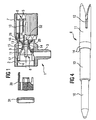
- the coaxial connector according to Figure 1 has an essentially cylindrical outer conductor housing 2, which is at right angles to its longitudinal axis protruding connector 3 for a not Has coaxial cable shown in detail on the rear End is open and has an internal thread 4 and at its front End of a longitudinally slotted and therefore with spring slats 5 trained outer conductor socket 6 and a union nut 7 to connect z. B. with a mating connector wearing.
- inner conductor 8 shown in the outer conductor housing 2 a one-piece insulating part 9 is provided. Training this insulating part 9 and the inner conductor 8 is in the following with reference to Figures 2 and 3 and Figure 4 described in more detail. According to FIG.
- the inner conductor 8 is on its front freely protruding from the insulating part 9 in FIG Plug-in section as a cylindrical plug pin 10 with a conical, rounded tip formed at the end.
- the rear End of the inner conductor 8, which also in the figure as free, not carried by the insulating part 9 end recognizable is the cylindrical connecting portion 11th of the inner conductor and is used to connect a bare or insulated electrical conductor, e.g. B. for connecting the inner conductor one over the connector 3 in the coaxial connector introduced coaxial cable.
- This is the connection section 11 of the inner conductor 8 with a clamping slot 12 formed, which for the connection of an insulated in particular electrical conductor of the insulation of the electrical Conductor penetrating cutting edges can be limited.
- the inner conductor 8 has a cylindrical central section 13, which - as can be clearly seen in FIG. 1 - forms the area in which the inner conductor 8 of the Insulating part 9 is worn.
- the inner conductor 8 with one provided here ring-shaped stop 14, the Outside diameter is larger than the outside diameter of the Middle section 13 so that the stop 14 the insertion of the Inner conductor 8 limited in the insulating part 9 when it is on one Stop 29 on the inner wall of the insulating part, for. B. on a diameter gradation.
- the one-piece, essentially hollow cylindrical insulating part 9 in Figures 2 and 3 has a relative diameter small middle section 15, on which on one side over a cone-shaped section 16 to the rear end 17 and on the other side, a stop designed in a ring shape here 18 and connect the front end 19, which alone the Inner conductor 8 picks up and carries.
- the insulating part 9 each has at least two radially resilient Clamping elements 20, 21 or 22, 23, which by two slots 24, 25 and 26, 27 are formed, respectively Longitudinal direction of the insulating part 9 and extend in the case of the rear end 17 of the insulating part from the free end face of the clamping elements 20, 21 over the conical section 16 to the middle section 15 and in the case of the front End 19 extend over its entire length.
- the biggest Outside diameter of the rear end 17 of the insulating part in Area of the approximately semi-cylindrical clamping elements 20, 21 is at least equal to the inner diameter of the outer conductor housing 2 in the area after its internal thread 4, so that Insulating part 9 inserted into the outer conductor housing 2 Condition by the resilient clamping elements 20, 21 on his fixed rear end by means of a clamp seat in the outer conductor housing is.
- the stop 18 of the insulating part 9 acts as a slide-in limitation by attaching it to a diameter step 28 abuts the inner wall of the outer conductor housing 2.
- the front end 19th of the insulating part 9 as well as the rear end 17 of the insulating part cross-sectionally cylindrical in the press fit area is, that is the cross-sectional shape of the front and of the rear end 19 or 17 of the insulating part 9 is in each case the cross-sectional shape of the inner conductor 8 or the outer conductor housing 2 adapted in the respective area.
- the one Part consists of insulating material and is a pressure piece 30, which is formed when tightening the screw 31 other part an electrical conductor in the clamping slot 12 of the inner conductor 8 presses.
Landscapes
- Coupling Device And Connection With Printed Circuit (AREA)
Claims (8)
- Connecteur coaxial comportant un conducteur interne (8) agencé de manière coaxiale dans un boítier du conducteur externe (2) et une pièce isolante (9) servant au support et au centrage du conducteur interne dans le boítier du conducteur externe, pouvant être insérée jusqu'à une butée dans le boítier du conducteur externe (2), caractérisé en ce que l'élément isolant (9) est constitué d'une seule pièce et comporte respectivement au niveau d'une extrémité avant et d'une extrémité arrière (19 respectivement 17) au moins deux éléments de serrage à élasticité radiale (22, 23) respectivement (20, 21), le diamètre extérieur maximal de l'extrémité arrière (17) de la pièce isolante (9) étant au moins égal au diamètre intérieur du boítier du conducteur externe (2), de sorte que la pièce isolante (9) est fixée au niveau de son extrémité arrière (17) par ajustement serré dans le boítier du conducteur externe (2) par l'intermédiaire des éléments de serrage élastiques (20, 21), le conducteur interne (8) pouvant être inséré jusqu'à une butée dans la pièce isolante (9) comportant entre une section de raccordement arrière libre (11) et une section d'enfichage libre avant (10) une section médiane (13), dont le diamètre extérieur est adapté au diamètre intérieur de l'extrémité avant (19) de la pièce isolante (9), les éléments de serrage élastiques (22, 23) de l'extrémité avant (19) de la pièce isolante (9) assurant sa fixation par ajustement serré dans la pièce isolante.
- Connecteur coaxial selon la revendication 1, caractérisé en ce que les éléments de serrage élastiques (22, 23 respectivement 20, 21) sont constitués au niveau de l'extrémité avant et de l'extrémité arrière (19 respectivement 17) de la pièce isolante (9) par des fentes (26, 27 respectivement 24, 25) s'étendant dans la direction longitudinale de la pièce isolante.
- Connecteur coaxial selon les revendications 1 ou 2, caractérisé en ce que l'extrémité avant et l'extrémité arrière (19 respectivement 17) de la pièce isolante (9) ont dans la région de l'ajustement serré une section transversale cylindrique.
- Connecteur coaxial selon l'une des revendications 1 à 3, caractérisé en ce que la pièce isolante (9) comporte une butée (18) entre les extrémités avant et arrière (19 respectivement 17).
- Connecteur coaxial selon l'une des revendications précédentes, caractérisé en ce que le conducteur interne (8) comporte entre sa section de raccordement arrière (11) et sa section médiane (13) une butée (14), dont le diamètre extérieur est supérieur au diamètre extérieur de la section médiane (13).
- Connecteur coaxial selon l'une des revendications précédentes, caractérisé en ce que la section d'enfichage avant du conducteur interne (8) a la forme d'une broche (10).
- Connecteur coaxial selon l'une des revendications précédentes, caractérisé en ce que la section de raccordement arrière libre (11) du conducteur interne (8) comporte une fente de serrage (12) en vue du raccordement avec un conducteur électrique, par exemple le conducteur interne d'un câble coaxial.
- Connecteur coaxial selon la revendication 7, caractérisé en ce que la fente de serrage (12) de la section de raccordement (11) est limitée par des arêtes de coupe pénétrant à travers l'isolation d'un conducteur électrique.
Applications Claiming Priority (2)
| Application Number | Priority Date | Filing Date | Title |
|---|---|---|---|
| DE19812206 | 1998-03-19 | ||
| DE19812206 | 1998-03-19 |
Publications (3)
| Publication Number | Publication Date |
|---|---|
| EP0944139A2 EP0944139A2 (fr) | 1999-09-22 |
| EP0944139A3 EP0944139A3 (fr) | 2001-12-12 |
| EP0944139B1 true EP0944139B1 (fr) | 2003-08-20 |
Family
ID=7861631
Family Applications (1)
| Application Number | Title | Priority Date | Filing Date |
|---|---|---|---|
| EP99104978A Expired - Lifetime EP0944139B1 (fr) | 1998-03-19 | 1999-03-12 | Connecteur coaxial avec pièce isolante pour le conducteur intérieur |
Country Status (2)
| Country | Link |
|---|---|
| EP (1) | EP0944139B1 (fr) |
| DE (1) | DE59906625D1 (fr) |
Families Citing this family (3)
| Publication number | Priority date | Publication date | Assignee | Title |
|---|---|---|---|---|
| ITMI20071433A1 (it) * | 2007-07-17 | 2009-01-18 | Compel Electronics S P A | Sistemi di connettori coassiali privi di saldatura e metodi di fabbricazione |
| ITRM20080642A1 (it) * | 2008-12-02 | 2010-06-03 | Maptel S R L Materiale Per Telefon Ia | "connettore senza saldatura per cavo coassiale" |
| ITFI20100027A1 (it) * | 2010-02-26 | 2011-08-27 | Duratel Spa | Connettore coassiale ad angolo senza saldature |
Family Cites Families (3)
| Publication number | Priority date | Publication date | Assignee | Title |
|---|---|---|---|---|
| DE7720087U1 (de) * | 1977-06-27 | 1977-11-10 | Spinner, Georg, Dr.-Ing., 8152 Feldkirchen-Westerham | HF-Koaxial-Steckvorrichtung |
| US5417588A (en) * | 1993-11-15 | 1995-05-23 | Adc Telecommunications, Inc. | Coax connector with center pin locking |
| DE9405333U1 (de) * | 1994-03-29 | 1994-05-26 | Siemens Ag | Koaxial-Steckverbinder mit einer Abstützung des Innenleiters |
-
1999
- 1999-03-12 DE DE59906625T patent/DE59906625D1/de not_active Expired - Lifetime
- 1999-03-12 EP EP99104978A patent/EP0944139B1/fr not_active Expired - Lifetime
Also Published As
| Publication number | Publication date |
|---|---|
| DE59906625D1 (de) | 2003-09-25 |
| EP0944139A3 (fr) | 2001-12-12 |
| EP0944139A2 (fr) | 1999-09-22 |
Similar Documents
| Publication | Publication Date | Title |
|---|---|---|
| DE2651704C3 (de) | Elektrischer Steckverbinder | |
| DE3141966C2 (fr) | ||
| EP0833412B1 (fr) | Broche de guidage pour connexions électriques | |
| EP1028498B1 (fr) | Connecteur pour câble coaxial ayant un conducteur extérieur lisse | |
| DE2261973A1 (de) | Steckanschlussvorrichtung fuer koaxialkabel | |
| DE1615644C3 (de) | Elektrischer Steckverbinder | |
| DE2826456A1 (de) | Elektrischer verbinder mit entstoerfilter | |
| DE2101617A1 (de) | Kabelendabschirmung | |
| DE112018000114T5 (de) | Hochfrequenz-Koaxialsteckverbinder mit Schnellkupplung | |
| DE2032651C3 (de) | Elektrisches Kontaktstück | |
| DE2731001C3 (de) | Elektrische Steckkontaktbuchse | |
| DE2647043C2 (de) | Zugentlastungsvorrichtung für eine Kabeleinführung in ein Gehäuse eines elektrischen Gerätes | |
| DE4316903C2 (de) | Kontaktierungsvorrichtung für den Metallgeflechtmantel geschirmter Leitungen | |
| EP0444478A1 (fr) | Porte-contact pour prise de courant ou connecteur pour le raccordement de remorques de véhicules | |
| EP0944139B1 (fr) | Connecteur coaxial avec pièce isolante pour le conducteur intérieur | |
| DE1953302A1 (de) | Elektrisches Kupplungsglied | |
| DE1921200A1 (de) | Koaxiale Anschlussvorrichtung fuer Hochfrequenzkabel | |
| DE102016003911B3 (de) | Rundsteckverbinder und Verfahren zum Montieren eines Rundsteckverbinders | |
| DE1440734B2 (de) | Einrichtung zur Halterung eines Kontaktgliedes in einem Verbindungsstück | |
| EP0918370B1 (fr) | Connecteur coaxial | |
| DE10237666B4 (de) | Steckverbinderelement | |
| EP0448760A1 (fr) | Connexion électrique à fiche | |
| DE1815801B2 (de) | Vorrichtung zur elektrischen verbindung der innenleiter von koaxialkabeln | |
| DE1297178B (de) | Werkzeug zum Ausbauen elektrischer Kontakte aus einer Leitungskupplung | |
| DE102019129190B3 (de) | Koaxial-Steckverbinder |
Legal Events
| Date | Code | Title | Description |
|---|---|---|---|
| PUAI | Public reference made under article 153(3) epc to a published international application that has entered the european phase |
Free format text: ORIGINAL CODE: 0009012 |
|
| AK | Designated contracting states |
Kind code of ref document: A2 Designated state(s): AT BE CH CY DE DK ES FI FR GB GR IE IT LI LU MC NL PT SE Kind code of ref document: A2 Designated state(s): AT BE CH DE DK ES FI LI |
|
| AX | Request for extension of the european patent |
Free format text: AL;LT;LV;MK;RO;SI |
|
| PUAL | Search report despatched |
Free format text: ORIGINAL CODE: 0009013 |
|
| AK | Designated contracting states |
Kind code of ref document: A3 Designated state(s): AT BE CH CY DE DK ES FI FR GB GR IE IT LI LU MC NL PT SE |
|
| AX | Request for extension of the european patent |
Free format text: AL;LT;LV;MK;RO;SI |
|
| RAP1 | Party data changed (applicant data changed or rights of an application transferred) |
Owner name: TYCO ELECTRONICS LOGISTICS AG |
|
| 17P | Request for examination filed |
Effective date: 20020213 |
|
| 17Q | First examination report despatched |
Effective date: 20020419 |
|
| GRAG | Despatch of communication of intention to grant |
Free format text: ORIGINAL CODE: EPIDOS AGRA |
|
| AKX | Designation fees paid |
Free format text: AT BE CH DE DK ES FI LI |
|
| RBV | Designated contracting states (corrected) |
Designated state(s): CH DE FR GB IT LI |
|
| GRAG | Despatch of communication of intention to grant |
Free format text: ORIGINAL CODE: EPIDOS AGRA |
|
| GRAH | Despatch of communication of intention to grant a patent |
Free format text: ORIGINAL CODE: EPIDOS IGRA |
|
| GRAH | Despatch of communication of intention to grant a patent |
Free format text: ORIGINAL CODE: EPIDOS IGRA |
|
| RIN1 | Information on inventor provided before grant (corrected) |
Inventor name: ACKE, EDGARD |
|
| GRAA | (expected) grant |
Free format text: ORIGINAL CODE: 0009210 |
|
| AK | Designated contracting states |
Designated state(s): CH DE FR GB IT LI |
|
| REG | Reference to a national code |
Ref country code: GB Ref legal event code: FG4D Free format text: NOT ENGLISH |
|
| RIC1 | Information provided on ipc code assigned before grant |
Ipc: 7H 01R 13/646 A |
|
| REG | Reference to a national code |
Ref country code: CH Ref legal event code: EP |
|
| REG | Reference to a national code |
Ref country code: CH Ref legal event code: NV Representative=s name: RIEDERER HASLER & PARTNER PATENTANWAELTE AG |
|
| REG | Reference to a national code |
Ref country code: IE Ref legal event code: FG4D Free format text: GERMAN |
|
| REF | Corresponds to: |
Ref document number: 59906625 Country of ref document: DE Date of ref document: 20030925 Kind code of ref document: P |
|
| GBT | Gb: translation of ep patent filed (gb section 77(6)(a)/1977) |
Effective date: 20031217 |
|
| REG | Reference to a national code |
Ref country code: IE Ref legal event code: FD4D |
|
| ET | Fr: translation filed | ||
| PLBE | No opposition filed within time limit |
Free format text: ORIGINAL CODE: 0009261 |
|
| STAA | Information on the status of an ep patent application or granted ep patent |
Free format text: STATUS: NO OPPOSITION FILED WITHIN TIME LIMIT |
|
| 26N | No opposition filed |
Effective date: 20040524 |
|
| PGFP | Annual fee paid to national office [announced via postgrant information from national office to epo] |
Ref country code: CH Payment date: 20050321 Year of fee payment: 7 |
|
| PG25 | Lapsed in a contracting state [announced via postgrant information from national office to epo] |
Ref country code: LI Free format text: LAPSE BECAUSE OF NON-PAYMENT OF DUE FEES Effective date: 20060331 Ref country code: CH Free format text: LAPSE BECAUSE OF NON-PAYMENT OF DUE FEES Effective date: 20060331 |
|
| REG | Reference to a national code |
Ref country code: CH Ref legal event code: PL |
|
| REG | Reference to a national code |
Ref country code: FR Ref legal event code: PLFP Year of fee payment: 18 |
|
| REG | Reference to a national code |
Ref country code: FR Ref legal event code: PLFP Year of fee payment: 19 |
|
| REG | Reference to a national code |
Ref country code: FR Ref legal event code: PLFP Year of fee payment: 20 |
|
| PGFP | Annual fee paid to national office [announced via postgrant information from national office to epo] |
Ref country code: DE Payment date: 20180227 Year of fee payment: 20 Ref country code: GB Payment date: 20180307 Year of fee payment: 20 |
|
| PGFP | Annual fee paid to national office [announced via postgrant information from national office to epo] |
Ref country code: IT Payment date: 20180321 Year of fee payment: 20 Ref country code: FR Payment date: 20180223 Year of fee payment: 20 |
|
| REG | Reference to a national code |
Ref country code: DE Ref legal event code: R071 Ref document number: 59906625 Country of ref document: DE |
|
| REG | Reference to a national code |
Ref country code: GB Ref legal event code: PE20 Expiry date: 20190311 |
|
| PG25 | Lapsed in a contracting state [announced via postgrant information from national office to epo] |
Ref country code: GB Free format text: LAPSE BECAUSE OF EXPIRATION OF PROTECTION Effective date: 20190311 |