EP0943858A1 - Casing for control apparatus - Google Patents
Casing for control apparatus Download PDFInfo
- Publication number
- EP0943858A1 EP0943858A1 EP98113292A EP98113292A EP0943858A1 EP 0943858 A1 EP0943858 A1 EP 0943858A1 EP 98113292 A EP98113292 A EP 98113292A EP 98113292 A EP98113292 A EP 98113292A EP 0943858 A1 EP0943858 A1 EP 0943858A1
- Authority
- EP
- European Patent Office
- Prior art keywords
- control unit
- unit housing
- channels
- handle
- housing according
- Prior art date
- Legal status (The legal status is an assumption and is not a legal conclusion. Google has not performed a legal analysis and makes no representation as to the accuracy of the status listed.)
- Withdrawn
Links
Images


Classifications
-
- H—ELECTRICITY
- H02—GENERATION; CONVERSION OR DISTRIBUTION OF ELECTRIC POWER
- H02B—BOARDS, SUBSTATIONS OR SWITCHING ARRANGEMENTS FOR THE SUPPLY OR DISTRIBUTION OF ELECTRIC POWER
- H02B15/00—Supervisory desks or panels for centralised control or display
-
- F—MECHANICAL ENGINEERING; LIGHTING; HEATING; WEAPONS; BLASTING
- F16—ENGINEERING ELEMENTS AND UNITS; GENERAL MEASURES FOR PRODUCING AND MAINTAINING EFFECTIVE FUNCTIONING OF MACHINES OR INSTALLATIONS; THERMAL INSULATION IN GENERAL
- F16M—FRAMES, CASINGS OR BEDS OF ENGINES, MACHINES OR APPARATUS, NOT SPECIFIC TO ENGINES, MACHINES OR APPARATUS PROVIDED FOR ELSEWHERE; STANDS; SUPPORTS
- F16M1/00—Frames or casings of engines, machines or apparatus; Frames serving as machinery beds
-
- H—ELECTRICITY
- H02—GENERATION; CONVERSION OR DISTRIBUTION OF ELECTRIC POWER
- H02B—BOARDS, SUBSTATIONS OR SWITCHING ARRANGEMENTS FOR THE SUPPLY OR DISTRIBUTION OF ELECTRIC POWER
- H02B1/00—Frameworks, boards, panels, desks, casings; Details of substations or switching arrangements
- H02B1/26—Casings; Parts thereof or accessories therefor
Definitions
- the invention relates to a control unit housing a front frame made of frame legs and Corner connector molded parts and with a handle device according to the preamble of claim 1.
- the housing of known control units are with provide additional grips to which in some Cases other accessories can be attached.
- a control device is described in DE 295 11 459 U1, with the housing on its open front side one of frame legs and corner connectors composite closed front frame is. About two spacers on each vertical sides of the front frame are handle bars appropriate. On a handle bar is by means of Connection clamps on with a terminal block provided concept holder.
- the spacers with the handlebars enlarge the outer dimensions of the housing and make a Source of danger and an additional cost and Cost of materials.
- the object of the invention is a control unit housing to develop which is more compact than the known ones is built, which is cheaper to produce and where the grips have additional functions able to fulfill.
- Control unit housing 1 from a front frame 3, which from four corner connector moldings 8 and Frame legs 9 is formed, and from a lower part 10th
- the two side frame legs 9 are as Handle strips 4 formed, the contour of the Corner connector moldings 8 is added so that the Run through the handle strips 4 from top to bottom.
- This Training conveys a homogeneous and aesthetic Overall impression.
- In the handle strips 4 are in their Longitudinal channels 5 are provided. These channels 5 can only in the corner connector moldings 8 or be designed as through channels. They serve that Adding more components or assemblies, what else is explained in more detail below.
- the front frame 3 is in the embodiment with the Lower part 10 firmly connected.
- the front frame 3 can but also by means of hinges and lock (not shown) pivotally connected to the lower part 10 his.
- the lower part 10 can be welded Sheet metal body made or from profiles be composed.
- FIG. 1 and 2 show how the front frame 3 via the channels 5 of the handle strips 4 for receiving different accessories can be used.
- the present example is a keyboard housing 2 grown.
- the attachment of the keyboard housing 2 to the Control unit housing 1 takes place by means of two curved ones Pipe pieces 6, the ends of which in the channels 5 and 5 ' Handle strips 4 and 4 'are inserted. Through the selected curvature of the pipe sections 6 can Keyboard housing 2 at an ergonomically correct angle be attached. It is also a retrofit to the control unit housing 1 possible.
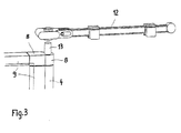
- FIG. 3 shows the possibility of a Drawing and concept holder 12 via a plug 13, which is only partially in the channel 5 of the handle 4 is introduced and one end of which from channel 5 protrudes, pivotable on the front frame 3 of the Attach control unit housing 1.
- All accessories for the front frame 3 are each in the channel 5 of the handle strips 4 left and right on Front frame 3 by means of not shown Cutting ring screws held. These are left and right, top and bottom, always radial to the channel bore available.
- the channel 5 is only used as a side handle 4 is used, then the holes in channels 5 with plug 11, which can also add colored accents, be closed (Fig. 2).
- the invention is not limited to that described here Embodiments limited. Rather, it is possible by combining the features more Realize embodiments without the frame to leave the invention.
Landscapes
- Engineering & Computer Science (AREA)
- Power Engineering (AREA)
- General Engineering & Computer Science (AREA)
- Mechanical Engineering (AREA)
- Advance Control (AREA)
- Regulating Braking Force (AREA)
- Vehicle Body Suspensions (AREA)
- Casings For Electric Apparatus (AREA)
Abstract
Description
Die Erfindung betrifft ein Steuergerätegehäuse mit
einem Frontrahmen aus Rahmenschenkeln und
Eckverbinderformteilen und mit einer Griffvorrichtung
gemäß dem Oberbegriff des Anspruchs 1.The invention relates to a control unit housing
a front frame made of frame legs and
Corner connector molded parts and with a handle device
according to the preamble of
Die Gehäuse bekannter Steuergeräte sind mit zusätzlichen Griffstücken versehen, an die in einigen Fällen weiteres Zubehör anbringbar ist.The housing of known control units are with provide additional grips to which in some Cases other accessories can be attached.
Im DE 295 11 459 U1 wird ein Steuergerät beschrieben, bei dem das Gehäuse an seiner offenen Frontseire mit einem aus Rahmenschenkeln und Eckverbindern zusammengesetzten geschlossenen Frontrahmen versehen ist. Über jeweils zwei Abstandsstücke an beiden vertikalen Seiten des Frontrahmens sind Griffstangen angebracht. An einer Griffstange ist mittels Verbindungsschellen ein mit einer Klemmleiste versehener Konzepthalter angeordnet.A control device is described in DE 295 11 459 U1, with the housing on its open front side one of frame legs and corner connectors composite closed front frame is. About two spacers on each vertical sides of the front frame are handle bars appropriate. On a handle bar is by means of Connection clamps on with a terminal block provided concept holder.
Die Abstandsstücke mit den Griffstangen vergrößern die äußeren Abmessungen des Gehäuses und stellen eine Gefahrenquelle und einen zusätzlichen Kosten- und Materialaufwand dar.The spacers with the handlebars enlarge the outer dimensions of the housing and make a Source of danger and an additional cost and Cost of materials.
Aufgabe der Erfindung ist es, ein Steuergerätegehäuse zu entwickeln, welches kompakter als die bekannten aufgebaut ist, welches kostengünstiger herstellbar ist und bei dem die Griffstücke zusätzliche Funktionen erfüllen können.The object of the invention is a control unit housing to develop which is more compact than the known ones is built, which is cheaper to produce and where the grips have additional functions able to fulfill.
Die Lösung dieser Aufgabe ergibt sich aus den Merkmalen
des Anspruchs 1. Zweckmäßige Ausgestaltungen der
Erfindung sind in den Unteransprüchen angegeben.The solution to this problem results from the features
of
Die Integration der Griffleisten gemäß der Erfindung in den Frontrabmen als dessen Bestandteil bringt insbesondere die folgenden Vorteile mit sich:
- Das Steuergerätegehäuse ist kompakt aufgebaut, es entsteht im wesentlichen kein zusätzlicher Raumbedarf bei der Anordnung an einer Maschine oder an eine Wand oder dgl..
- Es werden keine zusätzlichen Teile benötigt und damit Kosten eingespart.
- Der in den Griffleisten vorgesehene Kanal gewährleistet die mehrfache Nutzung der Griffleisten u.a. als Aufnahme für ein Tastaturgehäuse, zusätzliche Griffe, Zeichnungs- und Konzepthalter und dgl..
- Der Verschluß nicht benötigter öffnungen der Kanäle in den Griffleisten durch Stopfen kann farbige Akzente setzen.
- The control unit housing has a compact design, there is essentially no additional space requirement when arranged on a machine or on a wall or the like.
- No additional parts are required, which saves costs.
- The channel provided in the handle strips ensures multiple use of the handle strips, inter alia as a receptacle for a keyboard housing, additional handles, drawing and concept holders and the like.
- The closing of unnecessary openings in the channels in the handle strips by means of plugs can set colored accents.
Die Erfindung wird anhand eines in der Zeichnung dargestellten Ausführungsbeispiels eines Steuergerätegehäuses erläutert. Es zeigen:
- Fig. 1
- eine perspektivische Draufsicht auf das Steuergerätegehäuse mit angebrachtem Tastaturgehäuse und zusätzlichem Griff,
- Fig. 2
- die Seitenansicht des Steuergerätegehäuses nach Fig. 1 und
- Fig. 3
- die Darstellung einer Ecke des Frontrahmens mit Zeichnungs- und Konzepthalter.
- Fig. 1
- a top perspective view of the control unit housing with attached keyboard housing and additional handle,
- Fig. 2
- the side view of the control unit housing according to Fig. 1 and
- Fig. 3
- the representation of a corner of the front frame with drawing and concept holder.
Entsprechend der Darstellung in der Fig. 1 besteht das
Steuergerätegehäuse 1 aus einem Frontrahmen 3, welcher
aus vier Eckverbinderformteilen 8 und aus
Rahmenschenkeln 9 gebildet ist, und aus einem Unterteil
10.According to the representation in Fig. 1, there is
Die beiden seitlichen Rahmenschenkel 9 sind als
Griffleisten 4 ausgebildet, deren Kontur von den
Eckverbinderformteilen 8 aufgenommen wird, so daß die
Griffleisten 4 von oben bis unten durchlaufen. Diese
Ausbildung vermittelt einen homogenen und ästhetischen
Gesamteindruck. In den Griffleisten 4 sind in deren
Längserstreckung Kanäle 5 vorgesehen. Diese Kanäle 5
können nur in den Eckverbinderformteilen 8 oder aber
als Durchgangskanäle ausgebildet sein. Sie dienen dem
Anbau weiterer Bauteile oder Baugruppen, was weiter
unten noch näher ausgeführt wird.The two
Der Frontrahmen 3 ist im Ausführungsbeispiel mit dem
Unterteil 10 fest verbunden. Der Frontrahmen 3 kann
aber ebenso mittels Scharnieren und Schloß (nicht
dargestellt) schwenkbar mit dem Unterteil 10 verbunden
sein. Das Unterteil 10 kann als geschweißter
Blechkörper hergestellt oder aus Profilen
zusammengesetzt sein. The
In den Fig. 1 und 2 ist gezeigt, wie der Frontrahmen 3
über die Kanäle 5 der Griffleisten 4 zur Aufnahme von
unterschiedlichem Zubehör verwendet werden kann. Im
vorliegenden Beispiel ist ein Tastaturgehäuse 2
angebaut. Wie aus der Darstellung gemäß Fig. 1
hervorgeht, entspricht der Frontrahmen 3' dieses
Tastaturgehäuses 2 in seinem Aufbau dem Frontrahmen 3
des Steuergerätegehäuses 1, d.h. die seitlichen
Rahmenschenkel 9' des Frontrahmens 3' sind ebenfalls
als Griffleisten 4' mit Kanälen 5' ausgebildet. Dadurch
ist ein einheitliches Design gegeben.1 and 2 show how the
Der Anbau des Tastaturgehäuses 2 an das
Steuergerätegehäuse 1 erfolgt mittels zweier gebogener
Rohrstücke 6, deren Enden in die Kanäle 5 bzw. 5' der
Griffleisten 4 bzw. 4' eingesteckt sind. Durch die
gewählte Krümmung der Rohrstücke 6 kann das
Tastaturgehäuse 2 in ergonomisch richtigem Winkel
befestigt werden. Es ist auch ein nachträglicher Anbau
an das Steuergerätegehäuse 1 möglich.The attachment of the
Nach den Fig. 1 und 2 ist in die unteren Kanäle 5' des
Tastaturgehäuses 2 ein zusätzlicher Griff 7 aus
gebogenem Rohr eingesteckt. Dieser Griff 7 kann auch
direkt in die Kanäle 5 der Griffleisten 4 des
Frontrahmens 3 eingesteckt werden, wenn kein
Tastaturgehäuse 2 verwendet wird. Ebenso können in die
oberen Kanäle 5 anderes Zubehör wie Zeichnungs- und
Konzepthalter 12 schwenkbar eingebracht werden (Fig.
3).1 and 2 is in the lower channels 5 'of
In der Fig. 3 ist die Möglichkeit dargestellt, einen
Zeichnungs- und Konzepthalter 12 über einen Stopfen 13,
der nur teilweise in den Kanal 5 der Griffleiste 4
eingebracht ist und dessen eines Ende aus dem Kanal 5
herausragt, schwenkbar an den Frontrahmen 3 des
Steuergerätegehäuses 1 anzubringen.3 shows the possibility of a
Drawing and concept holder 12 via a
Alle Zubehöroptionen zum Frontrahmen 3 werden jeweils
in dem Kanal 5 der Griffleisten 4 links und rechts am
Frontrahmen 3 mittels nicht dargestellter
Schneidringschrauben gehalten. Diese sind links und
rechts, oben und unten, radial zur Kanalbohrung immer
vorhanden.All accessories for the
Wenn der Kanal 5 lediglich als seitliche Griffleiste 4
benutzt wird, dann können die Bohrungen der Kanäle 5
mit Stopfen 11, die auch farbige Akzente setzen können,
verschlossen werden (Fig. 2).If the
Die Erfindung ist nicht auf die hier beschriebenen Ausführungsformen beschränkt. Vielmehr ist es möglich, durch Kombination der Merkmale weitere Ausführungsbeispiele zu realisieren, ohne den Rahmen der Erfindung zu verlassen.The invention is not limited to that described here Embodiments limited. Rather, it is possible by combining the features more Realize embodiments without the frame to leave the invention.
Claims (10)
dadurch gekennzeichnet, daß
mindestens ein Rahmenschenkel (9) des Frontrahmens (3) als eine Griffleiste (4) ausgebildet ist.Control unit housing with a front frame made of frame legs and corner connector molded parts and with a handle device,
characterized in that
at least one frame leg (9) of the front frame (3) is designed as a grip strip (4).
dadurch gekennzeichnet, daß
die Griffleiste (4) einen Kanal (5) aufweist, der zum Anbau von unterschiedlichem Zubehör wie Tastaturgehäuse (2), Zeichnungs- und Konzepthalter (12) verwendbar ist.Control unit housing according to claim 1,
characterized in that
the grip strip (4) has a channel (5) which can be used to attach various accessories such as keyboard housing (2), drawing and concept holder (12).
dadurch gekennzeichnet, daß
beidseitig Griffleisten (4) mit jeweils einem Kanal (5) vorgesehen sind, und daß in die Kanäle (5) jeweils ein gebogenes Rohrstück (6) eingesteckt ist, über die das Tastaturgehäuse (2) in ergonomisch richtigem Winkel an das Steuergerätegehäuse (1) angebracht ist. Control unit housing according to claims 1 and 2,
characterized in that
Handle strips (4) are provided on both sides, each with a channel (5), and that a curved piece of pipe (6) is inserted into the channels (5), via which the keyboard housing (2) is connected to the control unit housing (1) at an ergonomically correct angle. is appropriate.
dadurch gekennzeichnet, daß
der Frontrahmen (3') des Tastaturgehäuses (2) ebenfalls Rahmenschenkel (9') mit integrierten Griffleisten (4') und Kanälen (5') aufweist und in die unteren Kanäle (5') ein Griff (7) aus gebogenem Rohr eingesteckt ist.Control unit housing according to claim 3,
characterized in that
the front frame (3 ') of the keyboard housing (2) also has frame legs (9') with integrated handle strips (4 ') and channels (5') and a handle (7) made of bent tube is inserted into the lower channels (5 ') .
dadurch gekennzeichnet, daß
in die Kanäle (5) der Griffleisten (4) ein Griff (7) eingesteckt ist.Control unit housing according to claims 1, 2 or 3,
characterized in that
a handle (7) is inserted into the channels (5) of the handle strips (4).
dadurch gekennzeichnet, daß
alle in die Kanäle (5, 5') eingebrachten Elemente (6' 7) mittels Schneidringschrauben gehalten sind.Control unit housing according to claims 1 to 5,
characterized in that
all elements (6 ', 7) introduced into the channels (5, 5') are held by means of cutting eye bolts.
dadurch gekennzeichnet, daß
die freien Kanäle (5, 5') der Griffleisten (4, 4') mit Stopfen (11) verschließbar sind. Control unit housing according to one of the preceding claims,
characterized in that
the free channels (5, 5 ') of the handle strips (4, 4') can be closed with plugs (11).
dadurch gekennzeichnet, daß
die Kanäle (5) in den Eckverbinderformteilen (8) ausgebildet sind.Control unit housing according to claims 1 to 7,
characterized in that
the channels (5) are formed in the corner connector molded parts (8).
dadurch gekennzeichnet, daß
die Kanäle (5) mittels Verrippungen im Profil als durchgehender Kanal ausgebildet sind.Control unit housing according to claims 1 to 7,
characterized in that
the channels (5) are formed as ribs in the profile as a continuous channel.
dadurch gekennzeichnet, daß
der Frontrahmen (3) fest oder schwenkbar mittels Scharnieren und Schloß auf einem geschweißten Blechkörper oder auf ein aus Profilen hergestelltes Unterteil (10) aufgesetzt ist.Control unit housing according to claims 1 to 9,
characterized in that
the front frame (3) is fixed or pivoted by means of hinges and lock on a welded sheet metal body or on a lower part (10) made of profiles.
Applications Claiming Priority (2)
| Application Number | Priority Date | Filing Date | Title |
|---|---|---|---|
| DE29804896U DE29804896U1 (en) | 1998-03-18 | 1998-03-18 | Control unit housing |
| DE29804896U | 1998-03-18 |
Publications (1)
| Publication Number | Publication Date |
|---|---|
| EP0943858A1 true EP0943858A1 (en) | 1999-09-22 |
Family
ID=8054379
Family Applications (1)
| Application Number | Title | Priority Date | Filing Date |
|---|---|---|---|
| EP98113292A Withdrawn EP0943858A1 (en) | 1998-03-18 | 1998-07-16 | Casing for control apparatus |
Country Status (2)
| Country | Link |
|---|---|
| EP (1) | EP0943858A1 (en) |
| DE (1) | DE29804896U1 (en) |
Cited By (1)
| Publication number | Priority date | Publication date | Assignee | Title |
|---|---|---|---|---|
| DE102004050497A1 (en) * | 2004-10-15 | 2006-05-04 | Rittal Gmbh & Co. Kg | Housing with a frame around the housing opening and attachable thereto attachments |
Families Citing this family (3)
| Publication number | Priority date | Publication date | Assignee | Title |
|---|---|---|---|---|
| DE29804896U1 (en) * | 1998-03-18 | 1998-06-04 | Rolec-Gehäusesysteme Rose + Rose GmbH & Co. KG, 31737 Rinteln | Control unit housing |
| DE19953729C1 (en) * | 1999-11-08 | 2001-07-19 | Loh Kg Rittal Werk | Machine operating control housing has front extension with inclined operating surface partially covered by support surface provided by removable console e.g. for supporting laptop computer |
| DE10119712C1 (en) * | 2001-04-20 | 2002-09-12 | Rittal Gmbh & Co Kg | Control device operating field mounting device uses bent pipe sections between lower edge of control device and rear edge of operating field |
Citations (8)
| Publication number | Priority date | Publication date | Assignee | Title |
|---|---|---|---|---|
| GB2085236A (en) * | 1980-10-08 | 1982-04-21 | Schroff Gmbh | Housing for electrical and electronic equipment |
| DE29511459U1 (en) | 1995-07-15 | 1995-09-28 | Rittal-Werk Rudolf Loh GmbH & Co. KG, 35745 Herborn | Control unit |
| DE19525880C1 (en) * | 1995-07-15 | 1996-07-25 | Loh Kg Rittal Werk | Control device operating field securing device |
| DE19525876C1 (en) * | 1995-07-15 | 1996-12-12 | Loh Kg Rittal Werk | Mounting frame for locating on to open front of equipment housing |
| DE19609795A1 (en) * | 1996-03-13 | 1997-07-03 | Loh Kg Rittal Werk | Housing for electrical and electronic controls e.g. for mouse |
| US5662397A (en) * | 1994-04-19 | 1997-09-02 | Rittal-Werk Rudolf Loh Gmbh & Co. Kg | Operating unit |
| DE19646019A1 (en) * | 1996-11-08 | 1998-05-14 | Loh Kg Rittal Werk | Electrical or electronic apparatus housing |
| DE29804896U1 (en) * | 1998-03-18 | 1998-06-04 | Rolec-Gehäusesysteme Rose + Rose GmbH & Co. KG, 31737 Rinteln | Control unit housing |
-
1998
- 1998-03-18 DE DE29804896U patent/DE29804896U1/en not_active Expired - Lifetime
- 1998-07-16 EP EP98113292A patent/EP0943858A1/en not_active Withdrawn
Patent Citations (8)
| Publication number | Priority date | Publication date | Assignee | Title |
|---|---|---|---|---|
| GB2085236A (en) * | 1980-10-08 | 1982-04-21 | Schroff Gmbh | Housing for electrical and electronic equipment |
| US5662397A (en) * | 1994-04-19 | 1997-09-02 | Rittal-Werk Rudolf Loh Gmbh & Co. Kg | Operating unit |
| DE29511459U1 (en) | 1995-07-15 | 1995-09-28 | Rittal-Werk Rudolf Loh GmbH & Co. KG, 35745 Herborn | Control unit |
| DE19525880C1 (en) * | 1995-07-15 | 1996-07-25 | Loh Kg Rittal Werk | Control device operating field securing device |
| DE19525876C1 (en) * | 1995-07-15 | 1996-12-12 | Loh Kg Rittal Werk | Mounting frame for locating on to open front of equipment housing |
| DE19609795A1 (en) * | 1996-03-13 | 1997-07-03 | Loh Kg Rittal Werk | Housing for electrical and electronic controls e.g. for mouse |
| DE19646019A1 (en) * | 1996-11-08 | 1998-05-14 | Loh Kg Rittal Werk | Electrical or electronic apparatus housing |
| DE29804896U1 (en) * | 1998-03-18 | 1998-06-04 | Rolec-Gehäusesysteme Rose + Rose GmbH & Co. KG, 31737 Rinteln | Control unit housing |
Cited By (2)
| Publication number | Priority date | Publication date | Assignee | Title |
|---|---|---|---|---|
| DE102004050497A1 (en) * | 2004-10-15 | 2006-05-04 | Rittal Gmbh & Co. Kg | Housing with a frame around the housing opening and attachable thereto attachments |
| DE102004050497B4 (en) * | 2004-10-15 | 2007-04-05 | Rittal Gmbh & Co. Kg | Housing with a frame around the housing opening and attachable thereto attachments |
Also Published As
| Publication number | Publication date |
|---|---|
| DE29804896U1 (en) | 1998-06-04 |
Similar Documents
| Publication | Publication Date | Title |
|---|---|---|
| EP0244582B1 (en) | Fittings for furniture construction | |
| DE29908103U1 (en) | Movement device for an armrest | |
| DE102012105717A1 (en) | Electromotive furniture drive | |
| DE102008056474A1 (en) | Central arm for receiving a contact grill or roasting top plate and contact grill or roasting device with such a central arm | |
| EP0839093B1 (en) | Control device | |
| DE4013371C1 (en) | Transverse rail fixer for frame shanks in electrical equipment cabinet - uses fitting plate and joint block with aligned threaded bores | |
| EP0943858A1 (en) | Casing for control apparatus | |
| DE60004112T2 (en) | Locking device for a door, in particular for a glass door | |
| EP0807371B1 (en) | Switch cabinet with rack and mounting plate | |
| DE3321441A1 (en) | Holder or support for fixing live busbars | |
| EP1029971A2 (en) | Ironing board | |
| DE19702863A1 (en) | Hinge for door, window etc. | |
| DE4423912B4 (en) | Vehicle seat, in particular motor vehicle seat | |
| DE19525880C1 (en) | Control device operating field securing device | |
| DE3421763C2 (en) | ||
| DE19518220A1 (en) | Pull-out device for a telecommunications equipment frame | |
| DE8710985U1 (en) | Electronic measuring device with a removable display and control unit | |
| DE10019997C2 (en) | Module housing, especially for an intercom | |
| DE3416675A1 (en) | DEVICE FOR CONNECTING DRIVE ROD SECTIONS OF A DRIVE ROD FITTING, IN PARTICULAR TURNTABLE FITTING FOR WINDOWS, DOORS OR THE LIKE | |
| DE202005019805U1 (en) | Hand rail bar e.g. for equipment, has at one end continuous plate and screw part which has even surface | |
| DE9107349U1 (en) | Door handle | |
| DE69836047T2 (en) | Device for hand-operated handles | |
| DE8132763U1 (en) | "Drilling jig" | |
| EP1217500A2 (en) | Arrangement for retaining a computer card | |
| DE9109770U1 (en) | Device for sealing a cable feedthrough hole in a control cabinet |
Legal Events
| Date | Code | Title | Description |
|---|---|---|---|
| PUAI | Public reference made under article 153(3) epc to a published international application that has entered the european phase |
Free format text: ORIGINAL CODE: 0009012 |
|
| AK | Designated contracting states |
Kind code of ref document: A1 Designated state(s): CH DE FR IT LI |
|
| AX | Request for extension of the european patent |
Free format text: AL;LT;LV;MK;RO;SI |
|
| 17P | Request for examination filed |
Effective date: 20000211 |
|
| AKX | Designation fees paid |
Free format text: CH DE FR IT LI |
|
| 17Q | First examination report despatched |
Effective date: 20030918 |
|
| STAA | Information on the status of an ep patent application or granted ep patent |
Free format text: STATUS: THE APPLICATION IS DEEMED TO BE WITHDRAWN |
|
| 18D | Application deemed to be withdrawn |
Effective date: 20041112 |