EP0943841A1 - All wheel drive continuously variable transmission having dual mode operation - Google Patents
All wheel drive continuously variable transmission having dual mode operation Download PDFInfo
- Publication number
- EP0943841A1 EP0943841A1 EP99301249A EP99301249A EP0943841A1 EP 0943841 A1 EP0943841 A1 EP 0943841A1 EP 99301249 A EP99301249 A EP 99301249A EP 99301249 A EP99301249 A EP 99301249A EP 0943841 A1 EP0943841 A1 EP 0943841A1
- Authority
- EP
- European Patent Office
- Prior art keywords
- driveably
- shaft
- input
- sun gear
- ring gear
- Prior art date
- Legal status (The legal status is an assumption and is not a legal conclusion. Google has not performed a legal analysis and makes no representation as to the accuracy of the status listed.)
- Granted
Links
Images
Classifications
-
- F—MECHANICAL ENGINEERING; LIGHTING; HEATING; WEAPONS; BLASTING
- F16—ENGINEERING ELEMENTS AND UNITS; GENERAL MEASURES FOR PRODUCING AND MAINTAINING EFFECTIVE FUNCTIONING OF MACHINES OR INSTALLATIONS; THERMAL INSULATION IN GENERAL
- F16H—GEARING
- F16H37/00—Combinations of mechanical gearings, not provided for in groups F16H1/00 - F16H35/00
- F16H37/02—Combinations of mechanical gearings, not provided for in groups F16H1/00 - F16H35/00 comprising essentially only toothed or friction gearings
- F16H37/021—Combinations of mechanical gearings, not provided for in groups F16H1/00 - F16H35/00 comprising essentially only toothed or friction gearings toothed gearing combined with continuous variable friction gearing
- F16H37/022—Combinations of mechanical gearings, not provided for in groups F16H1/00 - F16H35/00 comprising essentially only toothed or friction gearings toothed gearing combined with continuous variable friction gearing the toothed gearing having orbital motion
Definitions
- This invention relates to automatic transmissions for automotive vehicles. More particularly it pertains to such transmissions having a fixed ratio drive mechanism and a variable ratio drive mechanism.
- a conventional multiple speed transmission has a number of spaced speed ratio changes produced by selectively holding and releasing components of a planetary gear set.
- An infinitely variable transmission that employs two variable diameter pulleys, and a drive belt engaging the pulleys provides a continuously variable speed ratio over a broad range of engine speeds.
- a bladed hydrokinetic torque converter located in the drive path between an engine and the planetary gearing provides additional torque multiplication for accelerating a motor vehicle from rest.
- a stall torque ratio of about 2.5:1 may be realised using a torque converter.
- a continuously variable transmission combining a fixed drive unit, variable drive unit, and torque converter is described in UK Patent application GB-2180020, assigned to the assignee of the present invention.
- the drive ratio for the powertrain is reduced to 8:1 from approximately 20:1 when the fixed drive ratio is 2:1 and the final drive and axle system ratio is 4:1.
- the variable ratio drive is activated.
- the overall transmission ratio may be controlled from 8:1 down to 2:1.
- a continuously variable transmission comprising: an input shaft; an intermediate shaft; an output shaft; a variable ratio drive mechanism having an input, and an output driveably connected to the input and intermediate shaft, for producing a continuously variable ratio of the speed of the input to the speed of the output; a fixed ratio drive mechanism having a first element coaxial with the input shaft, and a second element driveably connected to the first element and intermediate shaft; a gearset driveably having a first sun gear driveably connected to the input shaft, a first ring gear surrounding the first sun gear, a carrier driveably connected to the output shaft, a set of long planet pinions rotatably supported on the carrier and meshing with the first sun gear and the first ring gear, a second sun gear a second ring gear surrounding the second sun gear, a set of second planet pinions rotatably supported on the carrier and meshing with the second ring gear, the second sun gear, and the long planet pinions; a transfer clutch for alternately driveably connecting and disconnecting the input of the
- a transmission embodying this invention has an advantage that it is able to accelerate a motor vehicle from rest through a speed reduction drive that bypasses a belt driven variable ratio drive mechanism so that the relatively large starting torque is carried by robust mechanical components and not by torque limited components, such as a drive belt.
- the transmission produces a continuously variable speed ratio over a range from the first gear (starting gear) ratio to the highest ratio, an overdrive ratio.
- the transmission is able to drive both front and rear wheels from two output shafts and without need for a transfer case to divide output torque carried on a single output shaft and to transmit torque to front and rear driveshafts.
- a continuously variable transmission includes an input shaft 12, rear output shaft 14, front output shaft 15, variable ratio drive mechanism 16, fixed ratio drive mechanism 18, a Ravigneau planetary gearset 20, and various clutches for controlling the mechanical elements of the transmission.
- Fixed ratio drive mechanism 18 driveably connects output shaft 14, which is driveably connected by a gearset carrier to sprocket wheel 24, and intermediate shaft 26, which supports a second sprocket wheel 28, sprockets 24, 28 being mutually driveably engaged through a chain 30.
- shaft 26 can be driveably connected to shaft 14 through another fixed ratio gear mechanism, such as a simple layshaft arrangement including gears in place of sprockets 24, 28 and an idler gear meshing with those gears so that shaft 26 turns in the same direction as shaft 14.
- the first sprocket 24 is rotatably supported on shaft 14; the second sprocket 28 is fixed to, and rotatably supported on intermediate shaft 26.
- the engine crankshaft 40 is driveably connected to a hydrokinetic torque converter 46 that includes a bladed impeller wheel 42 arranged in a toroidal fluid flow path with a bladed turbine wheel 44, arranged to be driven hydrodynamically by fluid exiting the impeller wheel.
- a bladed stator wheel 48 is located in the flow path between fluid entrance to the impeller and the fluid exit of the turbine.
- a one-way clutch 50 rotatably supports the stator wheel and allows it to rotate in one direction about the axis of shaft 12.
- the torus of the torque converter is filled with hydraulic fluid, and the turbine wheel 44 is supported rotatably on a turbine hub 52, which is connected driveably to input shaft 12.
- a hydraulically operated bypass clutch 54 alternately mechanically connects engine shaft 40 and input shaft 12 when clutch 54 is engaged, and allows impeller 42 to drive turbine 44 hydraulically when clutch 54 is disengaged.
- the torque converter produces torque amplification and speed reduction until it reaches coupling speed.
- Input shaft 12 is connected, preferably through torque converter 46, to a source of power, such as an internal combustion engine or electric motor.
- Rear output shaft 14 is driveably connected to the drive wheels of a motor vehicle, preferably to the rear wheels.
- Front output shaft 14 is driveably connected to the drive wheels of a motor vehicle, preferably to the front wheels.
- output shaft 14 can be connected to the front axles, and output shaft 15 can be connected to the rear axles.
- Variable ratio drive mechanism 16 includes a first sheave assembly, which includes pulleys 54, 56 supported rotatably on input shaft 12, and a second sheave assembly, which includes pulleys 58, 60 fixed to and supported rotatably on intermediate shaft 26.
- the axial position of one of the first pair of pulleys 54, 56 is fixed on the input shaft, the other pulley of the pair is moveable axially along the shaft, preferably in response to hydraulic pressure applied to an actuating device, so that the radial position of the drive belt 62 moves in accordance with the axial position of the axially displaceable pulley due to the inclined surfaces of the pulley faces that engage driveably the lateral surfaces of the drive belt 62.
- one of the pulleys 58, 60 on shaft 26 is fixed in its axial position, and the other pulley is axially displaceable so that the inclined inner faces of the pulleys are continually engaged at a variable radial position with lateral surfaces of drive pulley 62. Movement of the displaceable pulleys is mutually co-ordinated so that they maintain driving contact with the belt. In this way the speed ratio produced by mechanism 16 is continuously variable.
- Gearset 22 includes a sun gear 62 connected driveably to input shaft 12, a ring gear 64 coaxial with, and surrounding the sun gear, a set of long planet pinions 66 meshing with sun gear 62 and ring gear 64, and a revolving carrier 68, rotatably supporting planet pinions 66 and driveably connected to output shaft 14 and sprocket 24.
- the gearset further includes a second sun gear 74, a second set of planet pinions 70 supported on carrier 68 and meshing with pinions 66, and a second ring gear 72 coaxial with and surrounding sun gear 74 and meshing with planet pinions 70.
- the elements of the transmission according to this invention are controlled operatively by various clutches and brakes, preferably hydraulically actuated friction devices, including low brake 98, reverse brake 100, second brake 101, transfer clutch TRF 102, and torque on demand (TOD) clutch 104.
- These clutches may be hydraulically, mechanically or electrically operated.
- Low brake 98 alternately holds ring gear 64 against rotation and releases ring gear 64 to rotate;
- reverse brake 100 alternately holds and releases ring gear 72;
- second brake holds and releases sun gear 74;
- transfer clutch TRF 102 alternately driveably connects and releases pulleys 54, 56 and shaft 12;
- torque on demand (TOD) clutch 104 alternately driveably connects and releases intermediate shaft 26 and output shaft 15.
- First or low gear is produced by engaging low brake 98 and releasing all the other friction elements, except that clutch 104 is engaged when drive to both front and rear axles is desired, as discussed below.
- Brake 98 holds ring gear 64 against rotation, and sun gear 62 is driven by the input shaft 12. Therefore, carrier 68 and shaft 14, which is connected driveably to the rear wheels, are underdriven in the same direction as the direction and speed of the engine.
- Carrier 68 can drive the front axle through drive mechanism 18, shaft 26, TOD clutch 104 and shaft 15. In this way four-wheel drive and/or all wheel drive can be produced by engaging clutch 104.
- TOD clutch 104 is engaged to directly connect front output shaft 15 to the power source, or engagement of that clutch is modulated to control the magnitude of torque transmitted to shaft 15.
- An upshift to the continuously variable range from second speed is accomplished by engaging transfer clutch 102 and disengaging the other friction elements.
- TRF clutch 102 connects input shaft 12 to a first sheave, whose pulleys 54, 56 drive the pulleys 58, 60 of a second sheave through belt 62 at a variable speed ratio that depends on the relative diameters of the sheaves where belt 62 engages the pulleys.
- the TOD clutch 104 can be used to driveably connect the second sheave to the front output shaft 15, as described above.
- the speed ratio produced in first or low gear through operation of gear unit 22 is spaced slightly from the speed ratio at the lowest end of the continually variable range produced through operation of the variable ratio drive 16. In this way the transition from first gear to the lowest variable gear ratio is an upshift.
- Reverse drive is produced by engaging reverse band or brake 100, and disengaging the other friction elements, except that TOD clutch 104 may be engaged to drive the front wheels when desired, as explained below.
- These actions hold sun gear 74 fixed against rotation. Since sun gear 62 is connected to input shaft 12, grounding sun gear 74 causes carrier 68, which revolves due to rotation of pinions 70 on sun gear 72, to be underdriven in the opposite direction in comparison to the speed and direction of the engine.
- the rear wheels are driven in this way by carrier 68 through shaft 14.
- the carrier 68 also drives sprocket 24, from which the front wheels are driven through the fixed ratio mechanism 18, TOD clutch 104 and front output shaft 15.
Abstract
Description
- This invention relates to automatic transmissions for automotive vehicles. More particularly it pertains to such transmissions having a fixed ratio drive mechanism and a variable ratio drive mechanism.
- A conventional multiple speed transmission has a number of spaced speed ratio changes produced by selectively holding and releasing components of a planetary gear set. An infinitely variable transmission that employs two variable diameter pulleys, and a drive belt engaging the pulleys provides a continuously variable speed ratio over a broad range of engine speeds.
- A bladed hydrokinetic torque converter located in the drive path between an engine and the planetary gearing provides additional torque multiplication for accelerating a motor vehicle from rest. A stall torque ratio of about 2.5:1 may be realised using a torque converter.
- A continuously variable transmission combining a fixed drive unit, variable drive unit, and torque converter is described in UK Patent application GB-2180020, assigned to the assignee of the present invention. After the torque converter reaches its coupling phase, when the ratio of the hydrokinetic unit is 1:1, the drive ratio for the powertrain is reduced to 8:1 from approximately 20:1 when the fixed drive ratio is 2:1 and the final drive and axle system ratio is 4:1. At that time the variable ratio drive is activated. Upon further acceleration of the vehicle, the overall transmission ratio may be controlled from 8:1 down to 2:1.
- U.S. Patents 4,856,369, 4,836,049 and 3,203,277 describe continually variable transmissions that employ a variable drive mechanism and a fixed drive mechanism in combination with a torque converter and planetary gearing.
- According to the present invention, there is provided a continuously variable transmission comprising: an input shaft; an intermediate shaft; an output shaft; a variable ratio drive mechanism having an input, and an output driveably connected to the input and intermediate shaft, for producing a continuously variable ratio of the speed of the input to the speed of the output; a fixed ratio drive mechanism having a first element coaxial with the input shaft, and a second element driveably connected to the first element and intermediate shaft; a gearset driveably having a first sun gear driveably connected to the input shaft, a first ring gear surrounding the first sun gear, a carrier driveably connected to the output shaft, a set of long planet pinions rotatably supported on the carrier and meshing with the first sun gear and the first ring gear, a second sun gear a second ring gear surrounding the second sun gear, a set of second planet pinions rotatably supported on the carrier and meshing with the second ring gear, the second sun gear, and the long planet pinions; a transfer clutch for alternately driveably connecting and disconnecting the input of the variable ratio drive mechanism and the input shaft; and a low brake for alternately holding against rotation and releasing the first ring gear.
- A transmission embodying this invention has an advantage that it is able to accelerate a motor vehicle from rest through a speed reduction drive that bypasses a belt driven variable ratio drive mechanism so that the relatively large starting torque is carried by robust mechanical components and not by torque limited components, such as a drive belt. The transmission produces a continuously variable speed ratio over a range from the first gear (starting gear) ratio to the highest ratio, an overdrive ratio. The transmission is able to drive both front and rear wheels from two output shafts and without need for a transfer case to divide output torque carried on a single output shaft and to transmit torque to front and rear driveshafts.
- The invention will now be described, by way of example, with reference to the accompanying drawings, in which:
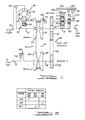
- Figure 1 is a schematic diagram of the kinematic arrangement for an automatic transmission according to the present invention; and
- Figure 2 is a chart showing the engaged and disengaged state of clutches and brakes of the transmission of Figure 1.
-
- Referring first to Figure 1, a continuously variable transmission according to this invention includes an
input shaft 12, rear output shaft 14,front output shaft 15, variableratio drive mechanism 16, fixedratio drive mechanism 18, a Ravigneauplanetary gearset 20, and various clutches for controlling the mechanical elements of the transmission. - Fixed
ratio drive mechanism 18 driveably connects output shaft 14, which is driveably connected by a gearset carrier to sprocketwheel 24, andintermediate shaft 26, which supports asecond sprocket wheel 28,sprockets chain 30. Alternatively,shaft 26 can be driveably connected to shaft 14 through another fixed ratio gear mechanism, such as a simple layshaft arrangement including gears in place ofsprockets shaft 26 turns in the same direction as shaft 14. Thefirst sprocket 24 is rotatably supported on shaft 14; thesecond sprocket 28 is fixed to, and rotatably supported onintermediate shaft 26. - The
engine crankshaft 40 is driveably connected to ahydrokinetic torque converter 46 that includes abladed impeller wheel 42 arranged in a toroidal fluid flow path with abladed turbine wheel 44, arranged to be driven hydrodynamically by fluid exiting the impeller wheel. Abladed stator wheel 48 is located in the flow path between fluid entrance to the impeller and the fluid exit of the turbine. A one-way clutch 50 rotatably supports the stator wheel and allows it to rotate in one direction about the axis ofshaft 12. The torus of the torque converter is filled with hydraulic fluid, and theturbine wheel 44 is supported rotatably on aturbine hub 52, which is connected driveably to inputshaft 12. A hydraulically operatedbypass clutch 54 alternately mechanically connectsengine shaft 40 andinput shaft 12 whenclutch 54 is engaged, and allowsimpeller 42 to driveturbine 44 hydraulically whenclutch 54 is disengaged. The torque converter produces torque amplification and speed reduction until it reaches coupling speed. -
Input shaft 12 is connected, preferably throughtorque converter 46, to a source of power, such as an internal combustion engine or electric motor. Rear output shaft 14 is driveably connected to the drive wheels of a motor vehicle, preferably to the rear wheels. Front output shaft 14 is driveably connected to the drive wheels of a motor vehicle, preferably to the front wheels. Alternatively, output shaft 14 can be connected to the front axles, andoutput shaft 15 can be connected to the rear axles. - Variable
ratio drive mechanism 16 includes a first sheave assembly, which includespulleys input shaft 12, and a second sheave assembly, which includespulleys 58, 60 fixed to and supported rotatably onintermediate shaft 26. The axial position of one of the first pair ofpulleys drive belt 62 moves in accordance with the axial position of the axially displaceable pulley due to the inclined surfaces of the pulley faces that engage driveably the lateral surfaces of thedrive belt 62. Similarly, one of thepulleys 58, 60 onshaft 26 is fixed in its axial position, and the other pulley is axially displaceable so that the inclined inner faces of the pulleys are continually engaged at a variable radial position with lateral surfaces ofdrive pulley 62. Movement of the displaceable pulleys is mutually co-ordinated so that they maintain driving contact with the belt. In this way the speed ratio produced bymechanism 16 is continuously variable. -
Gearset 22 includes asun gear 62 connected driveably to inputshaft 12, aring gear 64 coaxial with, and surrounding the sun gear, a set oflong planet pinions 66 meshing withsun gear 62 andring gear 64, and a revolvingcarrier 68, rotatably supportingplanet pinions 66 and driveably connected to output shaft 14 and sprocket 24. - The gearset further includes a
second sun gear 74, a second set ofplanet pinions 70 supported oncarrier 68 and meshing withpinions 66, and asecond ring gear 72 coaxial with and surroundingsun gear 74 and meshing withplanet pinions 70. - The elements of the transmission according to this invention are controlled operatively by various clutches and brakes, preferably hydraulically actuated friction devices, including
low brake 98,reverse brake 100, second brake 101,transfer clutch TRF 102, and torque on demand (TOD)clutch 104. These clutches may be hydraulically, mechanically or electrically operated.Low brake 98 alternately holdsring gear 64 against rotation and releasesring gear 64 to rotate;reverse brake 100 alternately holds and releasesring gear 72; second brake holds and releasessun gear 74; transfer clutch TRF 102 alternately driveably connects and releasespulleys shaft 12; and torque on demand (TOD)clutch 104 alternately driveably connects and releasesintermediate shaft 26 andoutput shaft 15. - First or low gear is produced by engaging
low brake 98 and releasing all the other friction elements, except thatclutch 104 is engaged when drive to both front and rear axles is desired, as discussed below. Brake 98 holdsring gear 64 against rotation, andsun gear 62 is driven by theinput shaft 12. Therefore,carrier 68 and shaft 14, which is connected driveably to the rear wheels, are underdriven in the same direction as the direction and speed of the engine.Carrier 68 can drive the front axle throughdrive mechanism 18,shaft 26,TOD clutch 104 andshaft 15. In this way four-wheel drive and/or all wheel drive can be produced by engagingclutch 104.TOD clutch 104 is engaged to directly connectfront output shaft 15 to the power source, or engagement of that clutch is modulated to control the magnitude of torque transmitted toshaft 15. - An upshift to the second speed results by disengaging
brake 98 and engaging second brake 101. This action holdssun gear 74 fixed against rotation and causescarrier 68 to be underdriven in the same direction as that of the engine. The front andrear output shafts 15, 14 may be driven as described above with reference to low speed operation. - An upshift to the continuously variable range from second speed is accomplished by
engaging transfer clutch 102 and disengaging the other friction elements. - In the CVT mode, TRF
clutch 102 connectsinput shaft 12 to a first sheave, whosepulleys pulleys 58, 60 of a second sheave throughbelt 62 at a variable speed ratio that depends on the relative diameters of the sheaves wherebelt 62 engages the pulleys. Shaft 26, which is driven bypulleys 58, 60, drives sprocket 28, which drives the rear output 14 and the rear wheels throughchain 30, sprocket 24 andcarrier 68. TheTOD clutch 104 can be used to driveably connect the second sheave to thefront output shaft 15, as described above. - Preferably the speed ratio produced in first or low gear through operation of
gear unit 22 is spaced slightly from the speed ratio at the lowest end of the continually variable range produced through operation of thevariable ratio drive 16. In this way the transition from first gear to the lowest variable gear ratio is an upshift. - Reverse drive is produced by engaging reverse band or
brake 100, and disengaging the other friction elements, except thatTOD clutch 104 may be engaged to drive the front wheels when desired, as explained below. These actions holdsun gear 74 fixed against rotation. Sincesun gear 62 is connected toinput shaft 12, groundingsun gear 74 causescarrier 68, which revolves due to rotation ofpinions 70 onsun gear 72, to be underdriven in the opposite direction in comparison to the speed and direction of the engine. The rear wheels are driven in this way bycarrier 68 through shaft 14. Thecarrier 68 also drives sprocket 24, from which the front wheels are driven through thefixed ratio mechanism 18,TOD clutch 104 andfront output shaft 15.
Claims (10)
- A continuously variable transmission comprising:an input shaft (12);an intermediate shaft (26);an output shaft (14,15);a variable ratio drive mechanism (16) having an input, and an output driveably connected to the input and intermediate shaft (12,26), for producing a continuously variable ratio of the speed of the input to the speed of the output;a fixed ratio drive mechanism (18) having a first element (24) coaxial with the input shaft (12), and a second element (28) driveably connected to the first element (24) and intermediate shaft (26);a gearset (20,22) driveably having a first sun gear (62) driveably connected to the input shaft (12), a first ring gear (64) surrounding the first sun gear (62), a carrier (68) driveably connected to the output shaft (14), a set of long planet pinions (66) rotatably supported on the carrier (68) and meshing with the first sun gear (62) and the first ring gear (64), a second sun gear (74), a second ring gear (72) surrounding the second sun gear (74), a set of second planet pinions (70) rotatably supported on the carrier (68) and meshing with the second ring gear (72), the second sun gear (74), and the long planet pinions;a transfer clutch (102) for alternately driveably connecting and disconnecting the input of the variable ratio drive mechanism (16) and the input shaft (12); anda low brake (98) for alternately holding against rotation and releasing the first ring gear (64).
- A transmission as claimed in claim 1, further comprising a second brake for alternately holding against rotation and releasing the second sun gear.
- A transmission as claimed in claim 1, further comprising:a second output shaft coaxial with the intermediate shaft; anda transfer clutch for alternately driveably connecting and disconnecting the intermediate shaft and second output shaft.
- A transmission as claimed in claim 1 further comprising a reverse brake for alternately holding against rotation and releasing the second ring gear, whereby the output shaft is driven in an opposite direction from the direction of the input shaft when the reverse brake is engaged.
- A transmission as claimed in claim 1, further comprising a torque converter having an impeller adapted for a driveable connection to a power source, a turbine adapted for a hydrokinetic drive connection to the impeller and driveably connected to the input shaft.
- A transmission as claimed in claim 1, whereinthe fixed ratio drive mechanism includes a first sprocket driveably fixed to the carrier of the gearset, a second sprocket driveably fixed to the intermediate shaft, and a flexible continuous element driveably engaging the input sprocket wheel and output sprocket wheel; andthe variable ratio drive includes a first sheave, a second sheave driveably fixed to the intermediate shaft, and a flexible continuous element driveably engaging the first sheave and second sheave at steplessly variable radial positions.
- A continuously variable transmission comprising:an input shaft;an intermediate shaft;an output shaft;a second output shaft;a variable ratio drive mechanism having an input coaxial with the input shaft, and an output driveably connected to the input and intermediate shaft, for producing a continuously variable ratio of the speed of the input to the speed of the output;a fixed ratio drive mechanism having an first element coaxial with the input shaft, and a second element driveably connected to the first element and intermediate shaft;a gearset driveably having a first sun gear driveably connected to the input shaft, a first ring gear surrounding the first sun gear, a carrier driveably connected to the output shaft, a set of long planet pinions rotatably supported on the carrier and meshing with the first sun gear and first ring gear, a second sun gear a second ring gear surrounding the first sun gear, a set of second planet pinions rotatably supported on the carrier and meshing with the second ring gear, second sun gear, and long planet pinions;a transfer clutch for alternately driveably connecting and disconnecting the input of the variable ratio drive mechanism and input shaft;a transfer clutch for alternately driveably connecting and disconnecting the input of the variable ratio drive mechanism and input shaft; anda low brake for alternately holding against rotation and releasing the ring gear.
- A continuously variable transmission comprising:an input shaft;an intermediate shaft;an output shaft;a variable ratio drive mechanism having a variable ratio drive includes a first sheave, a second sheave driveably fixed to the intermediate shaft, and a flexible continuous element driveably engaging the first sheave and second sheave at steplessly variable radial positions for producing a continuously variable ratio of the ratio of the speed of the second sheave to the speed of the first sheave;the fixed ratio drive mechanism includes a first sprocket, a second sprocket driveably fixed to the intermediate shaft, and a flexible continuous element driveably engaging the first sprocket and second sprocket;a gearset driveably having a first sun gear driveably connected to the input shaft, a first ring gear surrounding the first sun gear, a carrier driveably connected to the output shaft, a set of long planet pinions rotatably supported on the carrier and meshing with the first sun gear and first ring gear, a second sun gear a second ring gear surrounding the first sun gear, a set of second planet pinions rotatably supported on the carrier and meshing with the second ring gear, second sun gear, and long planet pinions;a transfer clutch for alternately driveably connecting and disconnecting the input of the variable ratio drive mechanism and input shaft; anda low brake alternately holding against rotation and releasing the ring gear; anda second brake for alternately holding against rotation and releasing the second sun gear.
- A transmission as claimed in claim 8, further comprising:a second output shaft; anda clutch for alternately driveably connecting and disconnecting the intermediate shaft and second output shaft.
- A transmission as claimed in claim 8, further comprising a reverse brake for alternately holding against rotation and releasing the ring gear of the second gearset, whereby the output shaft is driven at a slower speed and in the opposite direction than the speed and direction of the input shaft when the reverse brake is engaged.
Applications Claiming Priority (2)
| Application Number | Priority Date | Filing Date | Title |
|---|---|---|---|
| US09/044,335 US6036616A (en) | 1998-03-19 | 1998-03-19 | All wheel drive continously variable transmission having dual mode operation |
| US44335 | 1998-03-19 |
Publications (2)
| Publication Number | Publication Date |
|---|---|
| EP0943841A1 true EP0943841A1 (en) | 1999-09-22 |
| EP0943841B1 EP0943841B1 (en) | 2003-04-02 |
Family
ID=21931806
Family Applications (1)
| Application Number | Title | Priority Date | Filing Date |
|---|---|---|---|
| EP99301249A Expired - Lifetime EP0943841B1 (en) | 1998-03-19 | 1999-02-22 | All wheel drive continuously variable transmission having dual mode operation |
Country Status (3)
| Country | Link |
|---|---|
| US (1) | US6036616A (en) |
| EP (1) | EP0943841B1 (en) |
| DE (1) | DE69906412D1 (en) |
Cited By (4)
| Publication number | Priority date | Publication date | Assignee | Title |
|---|---|---|---|---|
| CN101649895B (en) * | 2009-09-07 | 2012-08-22 | 郭克亚 | Mixing type stepless speed change transmission device |
| CN104389971A (en) * | 2014-11-21 | 2015-03-04 | 顺德职业技术学院 | Stepless speed change transmission device for single row planetary gear mechanism |
| CN104595432A (en) * | 2014-11-21 | 2015-05-06 | 顺德职业技术学院 | Stepless speed regulation gear reversing transmission structure |
| CN105351498A (en) * | 2015-12-24 | 2016-02-24 | 江苏理工学院 | Dual-belt type continuously variable transmission for vehicle |
Families Citing this family (30)
| Publication number | Priority date | Publication date | Assignee | Title |
|---|---|---|---|---|
| DE19728611A1 (en) * | 1997-07-04 | 1999-02-04 | Zahnradfabrik Friedrichshafen | Continuously variable transmission |
| JP3280633B2 (en) * | 1999-03-24 | 2002-05-13 | 株式会社コミュータヘリコプタ先進技術研究所 | Helicopter power transmission |
| US6463866B2 (en) * | 1999-12-08 | 2002-10-15 | Edward Huffmeyer | Apparatus for varying the rate of seed population |
| US6640733B2 (en) | 1999-12-08 | 2003-11-04 | Edward H. Huffmeyer | Inclinometer-controlled apparatus for varying the rate of seed population |
| JP3458818B2 (en) * | 2000-03-30 | 2003-10-20 | 日産自動車株式会社 | Control device for infinitely variable speed ratio transmission |
| DE10249484A1 (en) * | 2002-10-24 | 2004-05-06 | Zf Friedrichshafen Ag | Dual area transmission unit with branched output, comprising two minus planetary gear sets and friction wheel alterator designed as single line device |
| US8025960B2 (en) * | 2004-02-02 | 2011-09-27 | Nanosys, Inc. | Porous substrates, articles, systems and compositions comprising nanofibers and methods of their use and production |
| US20050239091A1 (en) * | 2004-04-23 | 2005-10-27 | Collis Matthew P | Extraction of nucleic acids using small diameter magnetically-responsive particles |
| US7347800B2 (en) * | 2005-02-11 | 2008-03-25 | Eaton Corporation | Multi-speed power splitting CVT |
| US7473202B2 (en) * | 2005-04-15 | 2009-01-06 | Eaton Corporation | Continuously variable dual mode transmission |
| DE102007030576A1 (en) * | 2007-07-02 | 2009-01-08 | Flasin Faser Gmbh | High-strength fiber material made of natural fiber, process for its production and its use for the production of composite materials |
| EP2815152A1 (en) | 2012-02-15 | 2014-12-24 | Dana Limited | Transmission and driveline having a tilting ball variator continuously variable transmission |
| EP2893219A4 (en) | 2012-09-06 | 2016-12-28 | Dana Ltd | Transmission having a continuously or infinitely variable variator drive |
| JP6293148B2 (en) | 2012-09-07 | 2018-03-14 | デーナ リミテッド | Ball CVT including direct drive mode |
| WO2014039713A1 (en) | 2012-09-07 | 2014-03-13 | Dana Limited | Ivt based on a ball type cvp including powersplit paths |
| JP6247691B2 (en) | 2012-09-07 | 2017-12-13 | デーナ リミテッド | Ball type continuously variable transmission / continuously variable transmission |
| WO2014039439A1 (en) * | 2012-09-07 | 2014-03-13 | Dana Limited | Ball type cvt/ivt including planetary gear sets |
| JP6247690B2 (en) | 2012-09-07 | 2017-12-13 | デーナ リミテッド | Ball CVT with output connection power path |
| US10030748B2 (en) | 2012-11-17 | 2018-07-24 | Dana Limited | Continuously variable transmission |
| WO2014124063A1 (en) | 2013-02-08 | 2014-08-14 | Microsoft Corporation | Pervasive service providing device-specific updates |
| WO2014159756A2 (en) | 2013-03-14 | 2014-10-02 | Dana Limited | Continuously variable transmission and an infinitely variable transmission variatory drive |
| WO2014159755A2 (en) | 2013-03-14 | 2014-10-02 | Dana Limited | Ball type continuously variable transmission |
| WO2014170960A1 (en) * | 2013-04-16 | 2014-10-23 | トヨタ自動車株式会社 | Vehicle control device and method |
| US9546720B2 (en) * | 2013-04-17 | 2017-01-17 | Ford Global Technologies, Llc | Torque split continually variable transmission |
| JP2016520782A (en) | 2013-06-06 | 2016-07-14 | デーナ リミテッド | 3 mode front wheel drive and rear wheel drive continuously variable planetary transmission |
| US10030751B2 (en) | 2013-11-18 | 2018-07-24 | Dana Limited | Infinite variable transmission with planetary gear set |
| WO2015073948A2 (en) | 2013-11-18 | 2015-05-21 | Dana Limited | Torque peak detection and control mechanism for cvp |
| EP3158230A4 (en) | 2014-06-17 | 2018-03-07 | Dana Limited | Off-highway continuously variable planetary-based multimore transmission including infinite variable transmission and direct continuously variable tranmission |
| US10030594B2 (en) | 2015-09-18 | 2018-07-24 | Dana Limited | Abuse mode torque limiting control method for a ball-type continuously variable transmission |
| US10626970B2 (en) * | 2016-04-11 | 2020-04-21 | GM Global Technology Operations LLC | Multi-mode transmission including a continuously variable transmission |
Citations (3)
| Publication number | Priority date | Publication date | Assignee | Title |
|---|---|---|---|---|
| DE3212769A1 (en) * | 1982-04-06 | 1983-10-06 | Volkswagenwerk Ag | Transmission arrangement |
| DE4234747A1 (en) * | 1992-06-19 | 1993-12-23 | Nicolae Dr Ing Souca | Infinitely variable transmission for vehicle - consists of differential gear, V=belt variator, transmission ratio variator and guide mechanisms |
| WO1996035063A1 (en) * | 1995-05-05 | 1996-11-07 | Pascal Thery | Continuously variable, high performance transmission system for an engine, particularly of a motor vehicle |
Family Cites Families (7)
| Publication number | Priority date | Publication date | Assignee | Title |
|---|---|---|---|---|
| JPS60116959A (en) * | 1983-11-28 | 1985-06-24 | Toyota Central Res & Dev Lab Inc | Continuously variable transmission for car |
| JPS6396351A (en) * | 1986-10-08 | 1988-04-27 | Aisin Warner Ltd | Continuously variable transmission |
| US5470285A (en) * | 1993-07-20 | 1995-11-28 | Borg-Warner Automotive, Inc. | Compact continuously variable transmission layout for rear wheel drive vehicles |
| US5827146A (en) * | 1996-01-18 | 1998-10-27 | Kwang Yang Motor Co., Ltd. | Dual transmission for motorcycles |
| NL1002245C2 (en) * | 1996-02-05 | 1997-08-07 | Doornes Transmissie Bv | Continuously variable transmission. |
| US5697861A (en) * | 1996-02-13 | 1997-12-16 | New Venture Gear, Inc. | Full-time transfer case with synchronized layshaft-type range shift arrangement |
| US5803859A (en) * | 1997-05-23 | 1998-09-08 | General Motors Corporation | Powertrain with planetary gearing and a continuously variable ratio unit |
-
1998
- 1998-03-19 US US09/044,335 patent/US6036616A/en not_active Expired - Fee Related
-
1999
- 1999-02-22 DE DE69906412T patent/DE69906412D1/en not_active Expired - Lifetime
- 1999-02-22 EP EP99301249A patent/EP0943841B1/en not_active Expired - Lifetime
Patent Citations (3)
| Publication number | Priority date | Publication date | Assignee | Title |
|---|---|---|---|---|
| DE3212769A1 (en) * | 1982-04-06 | 1983-10-06 | Volkswagenwerk Ag | Transmission arrangement |
| DE4234747A1 (en) * | 1992-06-19 | 1993-12-23 | Nicolae Dr Ing Souca | Infinitely variable transmission for vehicle - consists of differential gear, V=belt variator, transmission ratio variator and guide mechanisms |
| WO1996035063A1 (en) * | 1995-05-05 | 1996-11-07 | Pascal Thery | Continuously variable, high performance transmission system for an engine, particularly of a motor vehicle |
Cited By (4)
| Publication number | Priority date | Publication date | Assignee | Title |
|---|---|---|---|---|
| CN101649895B (en) * | 2009-09-07 | 2012-08-22 | 郭克亚 | Mixing type stepless speed change transmission device |
| CN104389971A (en) * | 2014-11-21 | 2015-03-04 | 顺德职业技术学院 | Stepless speed change transmission device for single row planetary gear mechanism |
| CN104595432A (en) * | 2014-11-21 | 2015-05-06 | 顺德职业技术学院 | Stepless speed regulation gear reversing transmission structure |
| CN105351498A (en) * | 2015-12-24 | 2016-02-24 | 江苏理工学院 | Dual-belt type continuously variable transmission for vehicle |
Also Published As
| Publication number | Publication date |
|---|---|
| DE69906412D1 (en) | 2003-05-08 |
| EP0943841B1 (en) | 2003-04-02 |
| US6036616A (en) | 2000-03-14 |
Similar Documents
| Publication | Publication Date | Title |
|---|---|---|
| EP0943841B1 (en) | All wheel drive continuously variable transmission having dual mode operation | |
| EP0828094B1 (en) | A continually variable transmission | |
| US8257216B2 (en) | Infinitely variable transmission | |
| US4836049A (en) | Continually variable transmission having fixed ratio and variable ratio mechanisms | |
| US6106428A (en) | Compact dual mode continually variable transmission | |
| US5803858A (en) | Powertrain transmission with torque converter planetary gearing and a continuously variable transmission unit | |
| EP0322574B1 (en) | Continually variable transmission having torque regeneration operating mode | |
| US5916053A (en) | Dual mode operation continuously variable transmission having creeper low and reverse gears | |
| EP0987469B1 (en) | Single cavity toroidal traction drive continually variable transmission | |
| US5888161A (en) | All wheel drive continuously variable transmission having dual mode operation | |
| EP0943839B1 (en) | Dual mode continuously variable transmission for a all wheel drive vehicle | |
| US5931760A (en) | Dual mode continuously variable transmission having multiple torque input paths | |
| EP0943840B1 (en) | All wheel drive continuously variable transmission having dual mode operation | |
| US5941789A (en) | All wheel drive continuously variable transmission having dual mode operation | |
| US5803859A (en) | Powertrain with planetary gearing and a continuously variable ratio unit | |
| US5961414A (en) | Dual mode continuously variable transmission having multiple torque input paths | |
| EP0719960A2 (en) | Multiple-Speed automatic transmission for motor vehicles | |
| US5261861A (en) | Five-speed transaxle for automotive vehicles | |
| US5800304A (en) | Multiple-speed automatic transmission for an automotive vehicle | |
| KR0183219B1 (en) | Infinite variable-speed drive for avehicle | |
| KR0168388B1 (en) | Cvt for a vehicle | |
| KR200195843Y1 (en) | Stepless Transmission for Vehicles | |
| KR100260166B1 (en) | Cvt for vehicle | |
| KR0154072B1 (en) | Cvt for a vhicle | |
| KR100199168B1 (en) | Cvt for a vehicle |
Legal Events
| Date | Code | Title | Description |
|---|---|---|---|
| PUAI | Public reference made under article 153(3) epc to a published international application that has entered the european phase |
Free format text: ORIGINAL CODE: 0009012 |
|
| AK | Designated contracting states |
Kind code of ref document: A1 Designated state(s): DE FR GB |
|
| AX | Request for extension of the european patent |
Free format text: AL;LT;LV;MK;RO;SI |
|
| 17P | Request for examination filed |
Effective date: 20000226 |
|
| AKX | Designation fees paid |
Free format text: DE FR GB |
|
| 17Q | First examination report despatched |
Effective date: 20011108 |
|
| GRAH | Despatch of communication of intention to grant a patent |
Free format text: ORIGINAL CODE: EPIDOS IGRA |
|
| GRAH | Despatch of communication of intention to grant a patent |
Free format text: ORIGINAL CODE: EPIDOS IGRA |
|
| GRAA | (expected) grant |
Free format text: ORIGINAL CODE: 0009210 |
|
| AK | Designated contracting states |
Designated state(s): DE FR GB |
|
| REG | Reference to a national code |
Ref country code: GB Ref legal event code: FG4D |
|
| REF | Corresponds to: |
Ref document number: 69906412 Country of ref document: DE Date of ref document: 20030508 Kind code of ref document: P |
|
| PG25 | Lapsed in a contracting state [announced via postgrant information from national office to epo] |
Ref country code: DE Free format text: LAPSE BECAUSE OF FAILURE TO SUBMIT A TRANSLATION OF THE DESCRIPTION OR TO PAY THE FEE WITHIN THE PRESCRIBED TIME-LIMIT Effective date: 20030703 |
|
| RAP2 | Party data changed (patent owner data changed or rights of a patent transferred) |
Owner name: LAWRENCE TECHNOLOGICAL UNIVERSITY |
|
| ET | Fr: translation filed | ||
| PLBE | No opposition filed within time limit |
Free format text: ORIGINAL CODE: 0009261 |
|
| STAA | Information on the status of an ep patent application or granted ep patent |
Free format text: STATUS: NO OPPOSITION FILED WITHIN TIME LIMIT |
|
| 26N | No opposition filed |
Effective date: 20040105 |
|
| REG | Reference to a national code |
Ref country code: FR Ref legal event code: TP |
|
| PGFP | Annual fee paid to national office [announced via postgrant information from national office to epo] |
Ref country code: FR Payment date: 20060216 Year of fee payment: 8 |
|
| REG | Reference to a national code |
Ref country code: GB Ref legal event code: 732E |
|
| REG | Reference to a national code |
Ref country code: FR Ref legal event code: TP |
|
| GBPC | Gb: european patent ceased through non-payment of renewal fee |
Effective date: 20070222 |
|
| REG | Reference to a national code |
Ref country code: FR Ref legal event code: ST Effective date: 20071030 |
|
| PG25 | Lapsed in a contracting state [announced via postgrant information from national office to epo] |
Ref country code: GB Free format text: LAPSE BECAUSE OF NON-PAYMENT OF DUE FEES Effective date: 20070222 Ref country code: FR Free format text: LAPSE BECAUSE OF NON-PAYMENT OF DUE FEES Effective date: 20070228 |
|
| PGFP | Annual fee paid to national office [announced via postgrant information from national office to epo] |
Ref country code: GB Payment date: 20060221 Year of fee payment: 8 |