EP0943799B1 - Pulsationsdämpfer für eine Pumpe - Google Patents
Pulsationsdämpfer für eine Pumpe Download PDFInfo
- Publication number
- EP0943799B1 EP0943799B1 EP99104941A EP99104941A EP0943799B1 EP 0943799 B1 EP0943799 B1 EP 0943799B1 EP 99104941 A EP99104941 A EP 99104941A EP 99104941 A EP99104941 A EP 99104941A EP 0943799 B1 EP0943799 B1 EP 0943799B1
- Authority
- EP
- European Patent Office
- Prior art keywords
- gas
- diaphragm
- pulsation suppression
- suppression device
- pump
- Prior art date
- Legal status (The legal status is an assumption and is not a legal conclusion. Google has not performed a legal analysis and makes no representation as to the accuracy of the status listed.)
- Expired - Lifetime
Links
- 230000010349 pulsation Effects 0.000 title claims description 99
- 230000001629 suppression Effects 0.000 title claims description 77
- 239000007788 liquid Substances 0.000 claims description 102
- 230000007246 mechanism Effects 0.000 claims description 43
- 230000008602 contraction Effects 0.000 claims description 42
- 230000008859 change Effects 0.000 claims description 12
- 238000005192 partition Methods 0.000 claims description 9
- 239000000463 material Substances 0.000 claims description 6
- 229920000840 ethylene tetrafluoroethylene copolymer Polymers 0.000 claims description 5
- 229920001343 polytetrafluoroethylene Polymers 0.000 claims description 5
- 229920002981 polyvinylidene fluoride Polymers 0.000 claims description 5
- 239000002033 PVDF binder Substances 0.000 claims description 4
- 238000001514 detection method Methods 0.000 claims description 4
- 239000004810 polytetrafluoroethylene Substances 0.000 claims description 4
- 229920011301 perfluoro alkoxyl alkane Polymers 0.000 claims description 3
- 230000009471 action Effects 0.000 description 14
- 238000007599 discharging Methods 0.000 description 10
- 230000002093 peripheral effect Effects 0.000 description 9
- 230000008878 coupling Effects 0.000 description 7
- 238000010168 coupling process Methods 0.000 description 7
- 238000005859 coupling reaction Methods 0.000 description 7
- 230000003247 decreasing effect Effects 0.000 description 7
- 230000006378 damage Effects 0.000 description 5
- -1 polypropylene Polymers 0.000 description 5
- 239000004698 Polyethylene Substances 0.000 description 4
- 239000004743 Polypropylene Substances 0.000 description 4
- 230000004323 axial length Effects 0.000 description 4
- 239000004417 polycarbonate Substances 0.000 description 4
- 239000004800 polyvinyl chloride Substances 0.000 description 4
- 229920000915 polyvinyl chloride Polymers 0.000 description 4
- 229920006324 polyoxymethylene Polymers 0.000 description 3
- 239000011347 resin Substances 0.000 description 3
- 229920005989 resin Polymers 0.000 description 3
- 239000000126 substance Substances 0.000 description 3
- 238000005406 washing Methods 0.000 description 3
- 230000000712 assembly Effects 0.000 description 2
- 238000000429 assembly Methods 0.000 description 2
- 238000004891 communication Methods 0.000 description 2
- 239000012994 photoredox catalyst Substances 0.000 description 2
- 239000004033 plastic Substances 0.000 description 2
- 229920003023 plastic Polymers 0.000 description 2
- 230000009467 reduction Effects 0.000 description 2
- 229920001774 Perfluoroether Polymers 0.000 description 1
- 229930182556 Polyacetal Natural products 0.000 description 1
- 239000004952 Polyamide Substances 0.000 description 1
- 230000004888 barrier function Effects 0.000 description 1
- 230000008901 benefit Effects 0.000 description 1
- 229920001577 copolymer Polymers 0.000 description 1
- 238000006073 displacement reaction Methods 0.000 description 1
- 230000000694 effects Effects 0.000 description 1
- 230000001747 exhibiting effect Effects 0.000 description 1
- 239000012530 fluid Substances 0.000 description 1
- 230000005484 gravity Effects 0.000 description 1
- 239000004973 liquid crystal related substance Substances 0.000 description 1
- 230000007774 longterm Effects 0.000 description 1
- 238000012423 maintenance Methods 0.000 description 1
- 238000004519 manufacturing process Methods 0.000 description 1
- 238000010606 normalization Methods 0.000 description 1
- 229920002647 polyamide Polymers 0.000 description 1
- 229920000515 polycarbonate Polymers 0.000 description 1
- 229920000573 polyethylene Polymers 0.000 description 1
- 229920001155 polypropylene Polymers 0.000 description 1
- 230000002035 prolonged effect Effects 0.000 description 1
- 238000005086 pumping Methods 0.000 description 1
- 230000008439 repair process Effects 0.000 description 1
- 239000004065 semiconductor Substances 0.000 description 1
- BFKJFAAPBSQJPD-UHFFFAOYSA-N tetrafluoroethene Chemical group FC(F)=C(F)F BFKJFAAPBSQJPD-UHFFFAOYSA-N 0.000 description 1
Images


Classifications
-
- F—MECHANICAL ENGINEERING; LIGHTING; HEATING; WEAPONS; BLASTING
- F04—POSITIVE - DISPLACEMENT MACHINES FOR LIQUIDS; PUMPS FOR LIQUIDS OR ELASTIC FLUIDS
- F04B—POSITIVE-DISPLACEMENT MACHINES FOR LIQUIDS; PUMPS
- F04B11/00—Equalisation of pulses, e.g. by use of air vessels; Counteracting cavitation
- F04B11/0008—Equalisation of pulses, e.g. by use of air vessels; Counteracting cavitation using accumulators
- F04B11/0016—Equalisation of pulses, e.g. by use of air vessels; Counteracting cavitation using accumulators with a fluid spring
Definitions
- the present invention relates to a pulsation suppression device for a pump.
- a pulsation suppression device of this type is used for suppressing pulsation (pulsative pressure) of a discharge pressure which is produced by variation in the flow rate or the pressure when a reciprocal pump is operated. Therefore, the pulsation suppression device of the invention may be interposingly used in a liquid transporting pipe through which various processing chemical liquids such as a washing liquid used in a semiconductor production step, specifically, a surface washing liquid for washing an IC or a liquid crystal device is transported by a reciprocal pump.
- the proposed pulsation suppression device has a liquid chamber and a gas chamber which are separated from each other by an extendable and contractible barrier such as a bellows or a diaphragm.
- the liquid chamber has a role of temporarily storing the liquid (such as the chemical liquid) to be transported by a reciprocal pump
- the gas chamber has a role of being filled with a gas for suppressing pulsation.
- the capacity of the liquid chamber is changed by means of extension and contraction of the diaphragm so as to maintain the pressure balance between the liquid chamber and the gas chamber, thereby suppressing pulsation of the discharge pressure of the reciprocal pump.
- the pulsation suppression device further has a gas supply and discharge switching valve mechanism.
- the switching valve mechanism is provided with a function of, in accordance with a change in the capacity of the liquid chamber, being alternately switched to a normal mode in which the gas is not supplied to nor discharged from the gas chamber, a gas supply mode in which the gas is supplied to the gas chamber, and a gas discharge mode in which the gas is discharged from the gas chamber. These modes are switched over by means of a reciprocal operation of an operating rod interlocked with extension and contraction of the diaphragm.
- pulsation of the transported liquid due to the discharge pressure of the pump can be suppressed by means of a change in the capacity of the liquid chamber which is caused by extension and contraction of the diaphragm, and also the change in the capacity of the liquid chamber can be suppressed to a low degree by the gas chamber pressure adjusting function of the gas supply and discharge switching valve mechanism.
- US-A-4556087 discloses a pulsation damper with a housing which includes fluid-containing and a gas-containing compartments. A movable wall sealingly divides both compartments. An actuating rod is connected to the movable wall for joint movement therewith. An extension portion of the rod, which extends in a valve housing, has an annular recess movable into annular channels at axial spacings from the recess.
- One channel communicates with a discharge conduit while the other channel is supplied with pressurized gaseous medium, so that when the movable wall is axially displaced out of the equilibrium position by more than a predetermined distance the annular recess establishes communication between the recess and the respective channel increasing or relieving the pressure in the gas-containing compartment through a conduit system.
- EP0707173 discloses a similar arrangement. However instead of a piston valve the pulsation damper comprises valve assemblies each of which incorporats an operating lever having at its end a roller riding on the surface of a cam member carried at the upper end of the actuating rod. The valve assemblies are functioning for an increase or a relief of the pressure in the gas-containing compartment through a conduit system.
- All conventionally used pulsation suppression devices including the pulsation suppression device which has been proposed by the applicant has the following problem.
- a pulsation suppression device is accidentally operated under a condition where the gas is not supplied to the gas chamber, when the pressure of the transported liquid is abnormally raised, the pressure balance between the liquid chamber and the gas chamber is broken and the diaphragm abnormally extends.
- a closed end face of the thus extending diaphragm strongly collides with an end portion of the operating rod which is a part disposed in the gas chamber. This collision may cause the closed end face of the diaphragm to be deformed or damaged.
- an excessive force may be applied also to the operating rod, so that the operating rod is deformed or broken.
- the invention has been conducted in view of the above-mentioned circumstances.
- the presumption portion has a configuration comprising: a device body having a sealed container-like shape; a diaphragm which partitions an interior of the device body into a liquid chamber that can temporarily store a liquid to be transported by a reciprocal pump, and a gas chamber that is to be filled with a gas for suppressing pulsation, and which extends and contracts to change a capacity of the liquid chamber, thereby absorbing pulsation due to a discharge pressure of the transported liquid; a gas supply and discharge switching valve mechanism which is attached to an outside of the device body, and which, in accordance with a change in the capacity of the liquid chamber, is alternately switched to a normal mode in which the gas is not supplied to nor discharged from the gas chamber, a gas supply mode in which the gas is supplied to the gas chamber, and a gas discharge mode in which the gas is discharged from the gas chamber; and an operating rod which is reciprocated in interlock relationship with extension and contraction of the dia
- the diaphragm when the transported liquid discharged from the reciprocal pump flows out through the liquid chamber in the device body, the diaphragm extends in a peak portion of the discharge pressure curve, so as to increase the capacity of the liquid chamber, thereby absorbing a rise of the pressure, and contracts in a valley portion of the discharge pressure curve, so as to decrease the capacity of the liquid chamber, thereby absorbing a drop of the pressure.
- the gas supply and discharge switching valve mechanism when, during the operation of the pulsation suppression device, the variation range of the discharge pressure of the reciprocal pump is within a predetermined range, the gas supply and discharge switching valve mechanism is maintained to the normal mode by the action of the operating rod which is reciprocally operated in interlock relationship with extension and contraction of the diaphragm, and hence the gas is not supplied to nor discharged from the gas chamber.
- the capacity change of the liquid chamber due to extension and contraction of the diaphragm is suppressed to a low degree, and also pulsation of the transported liquid flowing out from the liquid chamber is suppressed to a low degree.
- the gas supply and discharge switching valve mechanism is switched to the gas supply mode by the action of the operating rod interlocked with extension of the diaphragm, and the gas is supplied to the gas chamber.
- the internal pressure of the gas chamber is raised so that extension of the diaphragm is suppressed.
- the gas supply and discharge switching valve mechanism is switched to the gas discharge mode by the action of the operating rod interlocked with contraction of the diaphragm, and the gas is discharged from the gas chamber.
- the internal pressure of the gas chamber is lowered so that contraction of the diaphragm is suppressed.
- the variation range of the discharge pressure of the reciprocal pump is increased or decreased to exceed the predetermined range, therefore, the capacity change of the liquid chamber due to extension or contraction of the diaphragm is suppressed to a low degree, and also pulsation of the transported liquid flowing out from the liquid chamber is suppressed to a low degree.
- the extension and contraction restricting mechanism is contacted with the closed end face of the diaphragm, thereby preventing the diaphragm from abnormally extending. Therefore, deformation and a damage of the diaphragm, and those of the stem-like operating rod which are due to the abutment between the diaphragm and the end portion of the operating rod are prevented from occurring.
- the extension and contraction restricting mechanism has a cylindrical end face which is contacted in parallel with the closed end face of the diaphragm. According to this configuration, also when the closed end face of the diaphragm abuts against the extension and contraction restricting mechanism formed by the cylindrical end face, the gas supplying and discharging action and the pulsation suppression function are appropriately exerted.
- the extension and contraction restricting mechanism is a mechanism formed by plural cylindrical end faces which are configured by end faces of plural cylindrical bodies that are concentrically arranged in the gas chamber, or a mechanism formed by a single annular plate which is fixedly disposed in the gas chamber.
- the length of each of the cylindrical bodies, or the position of the annular plate is preferably set to a position where the diaphragm can be prevented from abnormally extending, and is required to be set so that the extension amount is restricted to a safety value at which no destruction occurs.
- the plural cylindrical bodies and the annular plate have a flow hole having a size which does not impede a flow of the gas.
- the flow hole is preferably formed by a notch, a hole, or the like having a size which does not impair the strength of the cylindrical bodies or the annular plate.
- a liquid leakage detection sensor may be disposed in a position of a bottom portion of the gas chamber. According to this configuration, even when the liquid is caused by a damage of the diaphragm or the like to leak into the gas chamber, the liquid leakage is detected as soon as possible by the liquid leakage detection sensor, so that the leakage can be prevented from developing into a serious situation such as a leakage to the outside of the device body.
- the presumption portion has the same configuration as that of the pulsation suppression device for a pump described above. Therefore, a discharge pressure curve which shows variation of a discharge pressure of the reciprocal pump that is used with being attached to the pulsation suppression device of the invention forms a waveform in which a peak and a valley are alternatingly repeated as the time elapses.
- the presumption portion exerts the same functions as those which are exerted by the presumption portion of the pulsation suppression device for a pump described above, i.e., the function that a pressure drop is absorbed by a peak portion of the discharge pressure curve where the transported liquid discharged from the reciprocal pump flows out through the liquid chamber of the device body, the function that, irrespective of whether the variation range of the discharge pressure of the reciprocal pump is within the predetermined range or not, pulsation of the transported liquid flowing out from the liquid chamber is suppressed to a low degree by the mode switching of the gas supply and discharge switching valve mechanism, and the like functions.
- the characterizing portion of the pulsation suppression device is configured so as to, in addition to the above-mentioned configuration of the presumption portion, have a guide which allows the operating rod to slide and which guides the reciprocal operation of the operating rod in the extension and contraction directions of the diaphragm.
- the guide guides the reciprocal operation of the operating rod in the extension and contraction directions of the diaphragm, and hence the operating rod is prevented from being inclined. Therefore, reduction of the operation reliability of the switching valve mechanism for gas supply which is due to inclination of the operating rod does not occur, and a predetermined gas supplying and discharging action on the gas chamber is conducted correctly and stably.
- a configuration is employed in which the guide is formed in a projection end portion of a cylindrical member which is protrudingly disposed in the gas chamber, and a flow hole having a size that does not impede a flow of the gas is formed in the cylindrical member.
- the above-mentioned configuration in which the guide is formed in the projection end portion of the circular cylindrical member is employed because of the following reason. As compared with a case where the guide is formed in a projection end portion of a polygonal cylindrical member, the capacity to be occupied in the gas chamber is decreased so that the whole of the device can be easily reduced in size. At the same time, the gas supplying and discharging action on the gas chamber can be smoothly conducted without causing hindrance.
- the pulsation suppression device for a pump according to the invention has a spring which pressingly urges the diaphragm in a direction along which the capacity of the liquid chamber is reduced.
- This spring serves to enable contraction of the diaphragm to be smoothly conducted.
- the guide guides the reciprocal operation of the operating rod in the extension and contraction directions of the diaphragm so as to prevent the operating rod from being inclined, and hence also deformation of the spring is prevented from occurring. Therefore, reduction of the operation reliability of the switching valve mechanism for gas supply which is due to deformation of the spring does not occur, and a predetermined gas supplying and discharging action on the gas chamber is conducted correctly and stably.
- the guide has a flat seat which holds one end of the spring.
- the axial length of the spring can be shortened as far as possible. Consequently, this serves to prevent the spring from being deformed, thereby enabling a predetermined gas supplying and discharging action to be conducted correctly and stably.
- the guide may be made of a material which is selected from the group consisting of PP (polypropylene), PVC (polyvinylchloride), PE (polyethylene), PCM (polyacetal), PA (polyamide), PC (polycarbonate), PTFE (polytetrafluoroethylen plastics), ETFE (ethylene tetrafluoroethylene copolymer), PVDF (poly(vinylidene fluoride) plastics), and PFA (tetrafluoroethylene perfluoroalkoxy vinyl ether copolymer).
- PP polypropylene
- PVC polyvinylchloride
- PE polyethylene
- PCM polyacetal
- PA polyamide
- PC polycarbonate
- PTFE polytetrafluoroethylen plastics
- ETFE ethylene tetrafluoroethylene copolymer
- PVDF poly(vinylidene fluoride) plastics
- PFA tetrafluoro
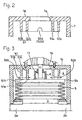
- Fig. 1 shows a pulsation suppression device for a pump which is an embodiment of the invention.
- a liquid chamber 3 is formed in an inner and lower portion of the device body 1 having a sealed container-like shape.
- the liquid chamber 3 has a role of temporarily storing a liquid Q which is supplied through an inflow port 2a and which is to be transported by a reciprocal pump.
- the transported liquid Q which is temporarily stored in the liquid chamber 3 is then transported to the outside through an outflow port 2b.
- a gas chamber 4 is formed in an inner and upper portion of the device body 1.
- the gas chamber 4 is separated from the liquid chamber 3 by an extendable and contractible member, specifically, for example, a bellows 5.
- a portion 5a surrounded by the bellows 5 is used as a part of the liquid chamber 3.
- a cylindrical coupling member 6 is placed in a center portion of a closed end face 5b of the bellows 5. The cylindrical coupling member 6 protrudes in a direction along which the capacity of the liquid chamber 3 is increased, i.e., the extension direction of the bellows 5, and is pressed against the closed end face 5b by the elastic urging force of a spring 18.
- An air supply and discharge switching valve mechanism 7 is mounted on the outer face of an upper wall 1a of the device body 1 which is positioned on the side of the gas chamber 4.
- a cylinder portion 9 is housed in a bottomed cylindrical casing 8.
- a slide valve element 10 is fitted into the cylinder portion 9 so as to be slidable in the axial direction (vertical direction) of the cylinder portion.
- a stem-like operating rod 11 is disposed so as to pass through a hole 1b formed in the upper wall 1a of the device body 1. The operating rod 11 is inserted into the gas chamber 4.
- An upper end portion of the operating rod 11 is coaxially coupled to by a pin to a lower end portion of the slide valve element 10.
- a coupling flange 11a on the lower end side of the operating rod 11 is coupled to a reference position in the cylindrical coupling member 6.
- the peripheral wall of the casing 8 has an air supply port 12 in a lower portion, and an air discharge port 13 in an upper portion.
- the air supply port 12 is used for supplying the air of a pressure which is not lower than the maximum pressure of the transported liquid Q.
- the air discharge port 13 is opened in the atmosphere.
- ports 14 and 15 are formed in the peripheral wall of the cylinder portion 9, respectively.
- An air supply and discharge passage 16a is formed in the peripheral wall of the casing 8.
- the air supply and discharge passage 16a is a passage through which the gas chamber 4 communicates with the interior of the cylinder portion 9.
- slide flanges 10a, 10b, and 10c are formed on the slide valve element 10 at predetermined spaces in the axial direction.
- the space between the center flange 10b and the lower flange 10c is formed as an air supply space S1
- the space between the center flange 10b and the upper flange 10a is formed as an air discharge space S2.
- the slide valve element 10 is alternately switched to a normal mode in which the air is not supplied to nor discharged from the gas chamber 4, an air supply mode in which the air is supplied to the gas chamber 4, and an air discharge mode in which the air is discharged from the gas chamber 4.
- the normal mode shown in Fig. 1 is maintained and the air supply and discharge passage 16a is isolated from the air supply space S1 and the air discharge space S2.
- the slide valve element 10 is raised so as to establish the air supply mode.
- the air supply port 12 communicates with the air supply and discharge passage 16a through the air supply space S1.
- the slide valve element 10 When the capacity of the gas chamber 4 is decreased by variation of the discharge pressure to exceed the predetermined range and the bellows 5 tries to contract with exceeding the predetermined range, the slide valve element 10 is lowered so as to establish the air discharge mode. In the air discharge mode, the air discharge port 13 communicates with the air supply and discharge passage 16a through the air discharge space S2.
- an extension and contraction restricting mechanism 51 is attached to the upper wall 1a of the device body 1.
- the extension and contraction restricting mechanism 51 has two cylindrical bodies 51A and 51B which are formed integrally with the upper wall 1a of the device body 1.
- the cylindrical bodies 51A and 51B are arranged concentrically with the operating rod 11 so as to protrude into the gas chamber 4 and have the same length.
- the lower end portions of the cylindrical bodies 51A and 51B are formed as cylinder end faces 51a and 51b which are parallel to the closed end face 5b of the bellows 5.
- the extension and contraction restricting mechanism 51 when the bellows 5 is caused to extend to a predetermined value by means of the cylindrical bodies 51A and 51B, the cylinder end faces 51a and 51b of the cylindrical bodies are contacted in parallel with the closed end face 5b of the bellows 5, thereby exhibiting an function of restricting further extension of the bellows 5.
- the number of cylindrical bodies is determined so that, when the bellows 5 is extendedly deformed to contact with the cylinder end faces, the closed end face 5b of the bellows 5 does not extend to exceed the predetermined value.
- the number is not restricted to two, and may be three or more.
- air flow holes 52A and 52B each configured by a notch having a size which does not impair the strength of the cylindrical body 51A or 51B are formed.
- the air flow holes 52A and 52B exert a function of, even when the bellows 5 extends to the predetermined value and the closed end face 5b is contacted with the cylinder end faces 51a and 51b in the lower ends of the cylindrical bodies 51A and 51B as shown in Fig. 3, causing the air in the gas chamber 4 to flow in the inward and outward directions as indicated by the arrows in the figure, whereby the pressure is maintained uniform over the whole range of the gas chamber 4.
- Each of the air flow holes 52A and 52B may be not configured by a notch, and instead may be configured by a through hole.
- the discharge pressure of the reciprocal pump When the reciprocal pump operates so as to transport the transported liquid Q toward a predetermined portion, the discharge pressure of the reciprocal pump generates pulsation corresponding to a discharge pressure curve in which peak and valley portions are repeated.
- the transported liquid Q which is supplied through the inflow port 2a is temporarily stored in the liquid chamber 3, and then flows out through the outflow port 2b.
- the air supply and discharge switching valve mechanism 7 In the case where the air supply and discharge switching valve mechanism 7 is held to the normal mode, when the discharge pressure of the transported liquid Q comes to a peak portion of the discharge pressure curve, the transported liquid Q causes the bellows 5 to extend in the direction along which the capacity of the liquid chamber 3 is increased, and hence the pressure is absorbed.
- the flow quantity of the transported liquid Q flowing out from the liquid chamber 3 is smaller than that of the liquid supplied from the pump.
- the discharge pressure of the transported liquid Q comes to a valley portion of the discharge pressure curve
- the pressure of the transported liquid Q becomes lower than the air pressure of the gas chamber 4 which is compressed by extension of the bellows 5, and hence the bellows 5 is contracted by the urge of the spring 18.
- the flow quantity of the transported liquid Q flowing from the pump into the liquid chamber 3 is larger than that of the liquid flowing out from the liquid chamber 3.
- the discharge pressure of the pump When the discharge pressure of the pump is varied in the increasing direction during such an operation, the quantity of the transported liquid Q is increased so as to increase the capacity of the liquid chamber 3, with the result that the bellows 5 largely extends.
- the slide valve element 10 When the extension amount of the bellows 5 exceeds the predetermined range, the slide valve element 10 is caused through the operating rod 11 to upward slide, and the air supply and discharge passage 16a communicates with the air supply port 12 through the air supply space 81, so that the air supply and discharge switching valve mechanism 7 is switched to the air supply mode. Therefore, the higher air pressure is supplied from the air supply port 12 to the gas chamber 4 via the air supply space S1, the air supply and discharge passage 16a, the interior of a cylindrical member 19, and a flow hole 19b, thereby raising the air pressure of the gas chamber 4.
- the extension amount of the bellows 5 is restricted, so that the capacity of the liquid chamber 3 is prevented from being excessively increased.
- pulsation is efficiently absorbed and the amplitude of pulsation is suppressed to a low level.
- the air a filled in the gas chamber 4 is discharged to the atmosphere from the air discharge port 13 via the flow hole 19b, the interior of the cylindrical member 19, the air supply and discharge passage 16a, and the air discharge space 82, thereby lowering the air pressure of the gas chamber 4.
- the contraction amount of the bellows 5 is restricted, so that the capacity of the liquid chamber 3 is prevented from being excessively decreased.
- pulsation is efficiently absorbed and the amplitude of pulsation is suppressed to a low level.
- the closed end face 5b of the bellows 5 is contacted in parallel with the cylinder end faces 51a and 51b of the cylindrical bodies 51A and 51B of the extension and contraction restricting mechanism 51 as shown in Fig. 3, thereby restricting further extension of the bellows 5. Therefore, deformation and a damage of the bellows 5, and those of the operating rod 11 which are due to the abutment between the bellows 5 and the lower end portion of the operating rod 11 are prevented from occurring. Consequently, the state where the operating rod 11 perpendicularly acts on the closed end face 5b of the bellows 5 is maintained.
- Figs. 4 and 5 show another embodiment.
- a single annular plate 51C which is horizontally placed in a predetermined level position of the gas chamber 4 is used as the extension and contraction restricting mechanism 51 of the bellows 5.
- the annular plate 51C is integrally fixed to the inner peripheral face of the device body 1.
- the closed end face 5b of the bellows makes in parallel full face contact or substantially full face contact with the lower face 51c of the annular plate 51C, thereby restricting further extension of the bellows 5.
- an air flow hole 52C configured by a notch or a through hole is formed in the annular plate 51C.
- the other configuration is identical with that of the embodiment which has been described with reference to Figs. 1 to 3. Therefore, the corresponding portions are designated by the same reference numerals, and their detailed description is omitted.
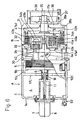
- Fig. 6 shows a further embodiment of another invention.
- the embodiment relates to a pulsation suppression device for an air driven bellows pump.
- a pulsation suppression portion A which is configured in the same manner as the pulsation suppression portions of the embodiments described above is disposed in one side of a partition wall 30 having the inflow port 2a and the outflow port 2b for the transported liquid.
- a reciprocal pump portion B is integrally disposed in the other side of the partition wall 30.
- the pulsation suppression portion A is configured in the same manner as the pulsation suppression device shown in Figs. 4 and 5. Therefore, the corresponding or equivalent portions are designated by the same reference numerals, and their detailed description is omitted.
- the configuration of the reciprocal pump portion B will be described.
- a bottomed cylindrical casing 31 is fixedly continuously disposed on the partition wall 30.
- a bellows 32 serving as a pump working member which is extendable and contractible in the axial direction of the cylinder is disposed in the bottomed cylindrical casing 31.
- An opening peripheral edge 32a of the bellows 32 is airtightly pressingly fixed to the partition wall 30 by an annular fixing plate 33.
- the inner space of the casing 31 is hermetically partitioned into a pump working chamber 34a inside the bellows 32, and a pump operating chamber 34b outside the bellows 32.
- a cylinder body 37 is fixed via a coupling member 35 to the outside of a bottom wall portion 31a of the bottomed cylindrical casing 31.
- a piston body 36 which is fixedly coupled to a closed end member 32b of the bellows 32 is slidably housed.
- Pressurized air which is fed from a pressurized air supplying device (not shown) such as a compressor is supplied to the interior of the cylinder body 37, or the pump operating chamber 34b via air holes 38a and 38b formed in the cylinder body 37 and the bottom wall portion 31a of the casing 31, thereby configuring an air cylinder portion 39 which drives the bellows 32 so as to be deformed by extension and contraction.
- a suction check valve 41a having a movable valve element 41a1, and a discharge check valve 41b having a movable valve element 41b1 are disposed in the suction port 40a and the discharge port 40b, respectively.
- the check valves are alternately opened and closed in accordance with extension and contraction of the bellows 32.
- the above-mentioned components constitute the reciprocal pump portion B.
- the transported liquid which is discharged from the pump working chamber 34a via the discharge check valve 41b in accordance with the operation of the reciprocal pump portion B is sent into the liquid chamber 3 in the pulsation suppression portion A through a communication passage 42 formed in the partition wall 30, to be temporarily stored in the liquid chamber 3, and then flows out to the outflow port 2b.
- the pump discharge pressure generates pulsation due to repetition of peak and valley portions.
- the pulsation is absorbed and suppressed by a change in the capacity of the liquid chamber 3.
- the pulsation suppression function and the function of restricting extension of the bellows 5 with respect to variation of the discharge pressure from the reciprocal pump portion B can be attained in the same manner as those which have been described with reference to Fig. 4 and the like.
- the air driven bellows pump of Fig. 6 is usually used as a horizontal type in order to extend and contract the bellows 5 and 32 in a horizontal direction. Therefore, a liquid leakage detection sensor 53 is disposed in a bottom position of the gas chamber 4 in the pulsation suppression portion A. According to this configuration, when liquid leakage from the liquid chamber 3 to the gas chamber 4 is caused by any chance by breakage of the bellows 5 or the like, the sensor 53 promptly detects the liquid leakage. When the liquid leakage is informed, it is possible to prevent the leakage from developing into a serious situation such as a leakage to the outside of the device body 1.
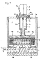
- the most portion of the pulsation suppression device is configured in the same manner as the device which has been described with reference to Fig. 1. Therefore, the portions corresponding to those shown in Fig. 1 are designated by the same reference numerals, and their detailed description is omitted. Hereinafter, the description will be made mainly on different portions.
- the cylindrical member 19 is disposed in the gas chamber 4 of the device body 1 so as to downward protrude from the upper portion.
- the cylindrical member 19 has a flange 19a in the upper end portion.
- a lower end flange 8a of the bottomed cylindrical casing 8 of the air supply and discharge switching valve mechanism 7 is opposed to the flange 19a.
- the flanges 8a and 19a under the opposed state are fixed to the upper wall 1a of the device body 1 by common bolts 20.
- the opening of the air supply and discharge passage 16a is positioned inside the upper end opening of the cylindrical member 19 which is fixed to the upper wall 1a of the device body 1 in this way.
- the cylindrical member 19 is made of a low-friction resin material which is selected from the group consisting of PP, PVC, PE, POM PA, PC, PTFE, ETFE, PVDF, and PFA.
- a guide 21 which slidingly guides the operation in the axial direction (vertical direction) of the operating rod 11 is formed in a projection end portion, i.e., the lower end portion of the cylindrical member 19.
- the flow hole 19b having a size that does not impede an air flow with respect to the gas chamber 4 is formed in a substantially middle portion in the axial direction of the peripheral wall of the cylindrical member 19.
- the lower face of the guide 21 is formed as a flat seat 22 which engagingly holds the upper end portion of the spring 18 which is interposed between the guide and the cylindrical coupling member 6.
- the spring 18 always exerts the function of elastically urging the bellows 5 in the direction of reducing the capacity of the liquid chamber 3.
- 17 denotes a spring member which is disposed in the casing 8, and which has a role of applying an upward spring force to the slide valve element 10 to hold the slide valve element 10 to the reference position.
- pulsation suppression device for a pump
- pulsation is suppressed by switching the mode of the air supply and discharge switching valve mechanism 7, in the same manner as the device which has been described with reference to Fig. 1.
- the axial reciprocal operation of the operating rod 11 which reciprocally operates in the axial direction in accordance with extension and contraction of the bellows 5 is slidingly guided by the guide 21.
- the gas chamber 4 is elongated in the extension and contraction directions of the bellows 5 so as to increase the internal capacity of the gas chamber 4, and the axial length of the operating rod 11 is elongated, therefore, the operating rod 11 which reciprocally operates is prevented from being inclined, and the spring 18 which urges the bellows 5 is prevented from being deformed. Consequently, the operating rod 11 perpendicularly acts on the bellows 5.
- the reliability of the mode switching i.e., the operation reliability of the air supply and discharge switching valve mechanism 7 which is interlocked with displacement of the bellows 5 is enhanced.
- the necessary length of the spring 18 can be suppressed to a short one, and hence it is easy to prevent the spring 18 from being deformed.
- the cylindrical member 19 constituting the guide 21 is made of a low-friction resin material which is selected from the group consisting of PP, PVC, PE, POM, PA, PC, PTFE, ETFE, PVDF, and PFA, the friction resistance in the reciprocal operation of the operating rod 11 can be reduced without using a special guiding device such as a bearing so that the expected pulsation suppression function is stably conducted.
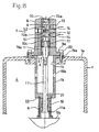
- FIG. 9 A still further embodiment of the invention will be described with reference to Fig. 9.
- the embodiment relates to a pulsation suppression device for an air driven bellows pump.
- a pulsation suppression portion A which is configured in the same manner as the pulsation suppression portion which has been described with reference to Figs. 7 and 8 is disposed in one side of the partition wall 30 having the inflow port 2a and the outflow port 2b for the transported liquid Q, and the reciprocal pump portion B is integrally disposed in the other side of the partition wall 30.
- the reciprocal pump portion B is configured in the same manner as the pump which has been described with reference to Fig. 6. Therefore, the corresponding or equivalent portions are designated by the same reference numerals, and their detailed description is omitted.
- the pulsation suppression function with respect to variation of the discharge pressure from the reciprocal pump portion B can be attained in the same manner as that of the embodiments which have been described above.
- the air driven bellows pump is usually used as a horizontal type in which the axial direction of the operating rod 11 elongates along a horizontal plane. When the operating rod 11 is long, therefore, the operating rod tends to be inclined by its gravity and the like. Even in such a horizontal type, the employment of the configuration in which the long operating rod 11 is slidingly guided by the guide 21 enables the effect of normalizing the air supplying and discharging action to be remarkably exerted.
- the lower end flange 8a of the bottomed cylindrical casing 8 of the air supply and discharge switching valve mechanism 7, and the upper end flange 19a of the cylindrical member 19 constituting the guide 21 are fixed under the opposed state to the upper wall 1a of the device body 1 by the common bolts 20.
- the employment of this configuration enables the operating rod 11 to be previously passed through the cylindrical member 19 via the cylindrical coupling member 6 and the spring 18 and then coupled to the slide valve element 10, and the coupled structure to, as an integral member, be fixed to or unfixed from the upper wall 1a of the device body 1. According to this configuration, therefore, maintenance including the assembly and repair of the whole device and replacement of a part can be facilitated.
Landscapes
- Engineering & Computer Science (AREA)
- Mechanical Engineering (AREA)
- General Engineering & Computer Science (AREA)
- Reciprocating Pumps (AREA)
- Pipe Accessories (AREA)
- Diaphragms And Bellows (AREA)
Claims (12)
- Pulsationsdämpfer für eine Pumpe, umfassend
einen Gerätekörper (1), in Form einer abgedichteten Dose;
eine Membran (5), welche einen Innenraum des Gerätekörpers in eine Flüssigkeitskammer (3), die vorübergehend eine durch eine Kolbenpumpe zu transportierende Flüssigkeit speichern kann, und eine Gaskammer (4) unterteilt, welche mit einem Gas zur Unterdrückung von Pulsationen gefüllt wird und sich erweitert und kontrahiert, um eine Kapazität der Flüssigkeitskammer zu ändern, wobei hierdurch Pulsationen aufgrund eines Ausgangsdrucks der transportierten Flüssigkeit gedämpft werden;
einen Gasvorrat und ein Auslaß-Ventilschaltmechanismus (7) welcher an einer Außenseite des Gerätekörpers befestigt ist und welcher in Übereinstimmung mit einer Änderung der Kapazität der Flüssigkeitskammer (3) abwechselnd in einen normalen Modus, in welchem das Gas weder in die Gaskammer eingelassen noch aus dieser ausgelassen wird, einen Gaseinlaßmodus, in welchem das Gas in die Gaskammer (4) eingelassen wird, und einen Gasauslaßmodus geschaltet wird, in welchem das Gas aus der Gaskammer ausgelassen wird; und
einen Betätigungsstab (11) welcher in umkehrendem Eingriff mit einer Erweiterung und Kontraktion der Membran (5) steht und welcher mittels der umkehrenden Funktion zwischen den Modi des Ventilschaltmechanismus (7) hin und her schaltet, wobei
das Gerät weiterhin einen Mechnismus zur Begrenzung der Erweiterung und Kontraktion (51) umfaßt, welcher in der Gaskammer (4) angeordnet ist und welcher mit einer geschlossenen Endfläche (5b) der sich bis auf einen
vorgegebenen Wert erweiterten Membran in Kontakt steht und hierbei eine weitere Erweiterung der Membran begrenzt,
dadurch gekennzeichnet, daß
der Mechnismus zur Begrenzung der Erweiterung und Kontraktion (51) eine zylindrische Endfläche (51a, 51b) aufweist, welche die geschlossene Endfläche (5b) der Membran parallel kontaktiert. - Pulsationsdämpfer für eine Pumpe gemäß Anspruch 1, wobei
der Mechanismus zur Begrenzung der Erweiterung und Kontraktion (51) durch mehrere zylindrische Endflächen (51a, 51b) geformt wird, welche durch die Endflächen mehrerer zylindrischer Körper (51A, 51B) gebildet werden, die konzentrisch in der Gaskammer (4) angeordnet sind. - Pulsationsdämpfer für eine Pumpe gemäß Anspruch 2, wobei
jeder der mehreren zylindrischen Körper (51A, 51B) eine Flußöffnung (52A, 52B) aufweist, die eine den Fluß des Gases nicht beeinträchtigende Größe hat. - Pulsationsdämpfer für eine Pumpe gemäß Anspruch 1, wobei
der Mechanismus zur Begrenzung der Erweiterung und Kontraktion (51) durch eine einzelne Ringförmige Platte (51C) ersetzt ist, welche in der Gaskammer (4) fest angeordnet ist. - Pulsationsdämpfer für eine Pumpe gemäß Anspruch 4, wobei
eine untere Fläche der ringförmigen Platte (51C) mit der geschlossenen Endfläche (5b) der Membran parallel kontaktiert wird. - Pulsationsdämpfer für eine Pumpe gemäß Anspruch 4, wobei
die ringförmige Platte eine Flußöffnung (52C) aufweist, die eine den Fluß des
Gases nicht beeinträchtigende Größe hat. - Pulsationsdämpfer für eine Pumpe gemäß Anspruch 1, wobei
der Gerätekörper in einer horizontalen Bauart ausgeführt ist, in welcher die Membran (5) sich in einer horizontalen Richtung erweitert und kontaktiert, und ein Sensor zur Erfassung von Leckageflüssigkeit (53) in einer Position eines Bodenabschnittes der Gaskammer angeordnet ist. - Pulsationsdämpfer für eine Pumpe gemäß Anspruch 1, wobei
das Gerät weiterhin eine Führung (6) aufweist, welche die Verschiebung des Betätigungsstabs (11) ermöglicht und welche die umkehrende Funktion des Betätigungsstabs in den Richtungen der Erweiterung und Kontraktion der Membran (5) führt. - Pulsationsdämpfer für eine Pumpe gemäß Anspruch 8, wobei
die Führung (6) in einem vorspringenden Endbereich eines zylindrischen Bauteils geformt ist, welches in die Gaskammer (4) hineinragend angeordnet ist, und in dem zylindrischen Teil eine Flußöffnung geformt ist, die eine den Fluß des Gases nicht beeinträchtigende Größe hat. - Pulsationsdämpfer für eine Pumpe gemäß Anspruch 9, wobei
das Gerät weiterhin eine Feder (18) umfaßt, welche die Membran (5) in eine Richtung drückt, entlang derer sich die Kapazität der Flüssigkeitskammer (3) verringert. - Pulsationsdämpfer für eine Pumpe gemäß Anspruch 10, wobei
die Führungseinrichtung (6) einen flachen Sitz aufweist, welcher ein Ende der Feder (18) aufnimmt. - Pulsationsdämpfer für eine Pumpe gemäß Anspruch 8, wobei
die Führung (6) aus einem Material besteht, welches aus einer Gruppe ausgewählt ist, die PP, PVC, PE, POM, PA, PC, PTFE, ETFE, PVDF und PFA enthält.
Applications Claiming Priority (4)
| Application Number | Priority Date | Filing Date | Title |
|---|---|---|---|
| JP7232198A JP2998083B2 (ja) | 1998-03-20 | 1998-03-20 | ポンプの脈動抑制装置 |
| JP10072322A JP3072555B2 (ja) | 1998-03-20 | 1998-03-20 | ポンプの脈動抑制装置 |
| JP7232298 | 1998-03-20 | ||
| JP7232198 | 1998-03-20 |
Publications (3)
| Publication Number | Publication Date |
|---|---|
| EP0943799A2 EP0943799A2 (de) | 1999-09-22 |
| EP0943799A3 EP0943799A3 (de) | 2000-10-18 |
| EP0943799B1 true EP0943799B1 (de) | 2004-10-13 |
Family
ID=26413459
Family Applications (1)
| Application Number | Title | Priority Date | Filing Date |
|---|---|---|---|
| EP99104941A Expired - Lifetime EP0943799B1 (de) | 1998-03-20 | 1999-03-12 | Pulsationsdämpfer für eine Pumpe |
Country Status (3)
| Country | Link |
|---|---|
| US (1) | US6095194A (de) |
| EP (1) | EP0943799B1 (de) |
| DE (1) | DE69920997T2 (de) |
Cited By (1)
| Publication number | Priority date | Publication date | Assignee | Title |
|---|---|---|---|---|
| US20220341406A1 (en) * | 2021-04-27 | 2022-10-27 | Blacoh Fluid Controls, Inc. | Automatic fluid pump inlet stabilizers and vacuum regulators |
Families Citing this family (18)
| Publication number | Priority date | Publication date | Assignee | Title |
|---|---|---|---|---|
| GB9920213D0 (en) * | 1999-08-27 | 1999-10-27 | Binks Ltd | Pressure regulation apparatus |
| JP3205909B2 (ja) * | 1999-10-25 | 2001-09-04 | 日本ピラー工業株式会社 | 脈動低減装置付きポンプ |
| JP3577435B2 (ja) * | 1999-11-29 | 2004-10-13 | 日本ピラー工業株式会社 | ベローズを有する流体機器 |
| JP3610272B2 (ja) * | 1999-11-29 | 2005-01-12 | 日本ピラー工業株式会社 | ベローズを有する流体機器 |
| JP2001153053A (ja) * | 1999-11-29 | 2001-06-05 | Nippon Pillar Packing Co Ltd | ベローズを有する流体機器 |
| JP3564362B2 (ja) * | 2000-05-10 | 2004-09-08 | 日本ピラー工業株式会社 | 脈動減衰装置 |
| US7096868B2 (en) * | 2004-03-09 | 2006-08-29 | Nellcor Puritan Bennett Incorporated | Laryngeal airway device |
| DE502005001026D1 (de) * | 2005-06-09 | 2007-08-23 | Thomas Magnete Gmbh | Dosierpumpe |
| CN102536778A (zh) * | 2010-12-29 | 2012-07-04 | 郑州大学 | 高压柱塞水泵进口液流脉动隔振装置 |
| EP3204733B1 (de) | 2014-10-08 | 2022-05-11 | Versum Materials US, LLC | Flusssteuerungsvorrichtung mit geringer druckschwankung und verfahren |
| GB201601194D0 (en) * | 2016-01-22 | 2016-03-09 | Carlisle Fluid Tech Inc | Active surge chamber |
| DE102017107601B4 (de) | 2017-04-10 | 2019-11-07 | Gardner Denver Deutschland Gmbh | Verfahren zur Steuerung eines Schraubenverdichters |
| DE102017107602B3 (de) | 2017-04-10 | 2018-09-20 | Gardner Denver Deutschland Gmbh | Kompressoranlage mit interner Luft-Wasser-Kühlung |
| DE102017107599A1 (de) | 2017-04-10 | 2018-10-11 | Gardner Denver Deutschland Gmbh | Pulsations-Schalldämpfer für Kompressoren |
| CN107246387A (zh) * | 2017-06-28 | 2017-10-13 | 哈尔滨工程大学 | 一种基于膜片式减振蓄能结构的三螺杆泵 |
| CN107940158A (zh) * | 2017-12-08 | 2018-04-20 | 李笑达 | 流体滤波器及其系统 |
| KR102100914B1 (ko) * | 2019-02-01 | 2020-04-17 | 한국원자력연구원 | 유체 이송 장치 |
| CN116464854A (zh) * | 2023-06-05 | 2023-07-21 | 氢友(上海)智能科技有限公司 | 自调节空气缓冲器 |
Family Cites Families (15)
| Publication number | Priority date | Publication date | Assignee | Title |
|---|---|---|---|---|
| US1950107A (en) * | 1932-07-30 | 1934-03-06 | Welford P Guinn | Pressure alleviator |
| US2828760A (en) * | 1953-05-19 | 1958-04-01 | British Messier Ltd | Automatic cut-outs for hydraulic circuits |
| FR1391050A (fr) * | 1964-01-17 | 1965-03-05 | Rech Etudes Production Sarl | Accumulateur hydropneumatique de sécurité, applicable notamment aux circuits hydrauliques des aérodynes |
| US3351097A (en) * | 1964-07-27 | 1967-11-07 | Bell Aerospace Corp | Hydraulic reservoir |
| US3454050A (en) * | 1967-01-31 | 1969-07-08 | Pressure Products Ind Inc | Accumulators |
| DE3411592C2 (de) * | 1984-03-29 | 1994-06-30 | Hydac Technology Gmbh | Hydropneumatischer Speicher |
| US4799048A (en) * | 1984-09-28 | 1989-01-17 | Nippondenso Co., Ltd. | Accumulator |
| US4646782A (en) * | 1984-10-22 | 1987-03-03 | Westinghouse Electric Corp. | Surge suppressing check valve |
| US4556087A (en) * | 1984-12-20 | 1985-12-03 | Itt Corporation | Pulsation damper |
| US4691739A (en) * | 1986-09-02 | 1987-09-08 | United Aircraft Products, Inc. | Bootstrap reservoir |
| JPH0617752A (ja) * | 1992-07-01 | 1994-01-25 | Iwaki:Kk | 脈動減少装置 |
| GB9420830D0 (en) * | 1994-10-15 | 1994-11-30 | Binks Bullows Ltd | Surge suppressor |
| JP2808415B2 (ja) * | 1994-12-12 | 1998-10-08 | 日本ピラー工業株式会社 | ポンプの脈動幅抑制装置 |
| JPH1072321A (ja) | 1996-08-29 | 1998-03-17 | Sansho Seiyaku Co Ltd | 育毛剤 |
| JPH1072322A (ja) | 1996-08-30 | 1998-03-17 | Seiwa Kasei:Kk | 毛髪用化粧品 |
-
1999
- 1999-03-10 US US09/265,355 patent/US6095194A/en not_active Expired - Lifetime
- 1999-03-12 EP EP99104941A patent/EP0943799B1/de not_active Expired - Lifetime
- 1999-03-12 DE DE69920997T patent/DE69920997T2/de not_active Expired - Fee Related
Cited By (3)
| Publication number | Priority date | Publication date | Assignee | Title |
|---|---|---|---|---|
| US20220341406A1 (en) * | 2021-04-27 | 2022-10-27 | Blacoh Fluid Controls, Inc. | Automatic fluid pump inlet stabilizers and vacuum regulators |
| US11549523B2 (en) * | 2021-04-27 | 2023-01-10 | Blacoh Fluid Controls, Inc. | Automatic fluid pump inlet stabilizers and vacuum regulators |
| US11828303B2 (en) | 2021-04-27 | 2023-11-28 | Blacoh Fluid Controls, Inc. | Automatic fluid pump inlet stabilizers and vacuum regulators |
Also Published As
| Publication number | Publication date |
|---|---|
| EP0943799A2 (de) | 1999-09-22 |
| DE69920997T2 (de) | 2006-03-09 |
| US6095194A (en) | 2000-08-01 |
| DE69920997D1 (de) | 2004-11-18 |
| EP0943799A3 (de) | 2000-10-18 |
Similar Documents
| Publication | Publication Date | Title |
|---|---|---|
| EP0943799B1 (de) | Pulsationsdämpfer für eine Pumpe | |
| KR100552137B1 (ko) | 흡인 밸브 | |
| KR101401213B1 (ko) | 오프셋 밸브 축을 갖는 다이어프램 펌프 위치 제어 | |
| EP1132668B1 (de) | Rückschlagventil | |
| EP1096147B1 (de) | Balgdämpfer für Druckschwingungen in einer Faltenbalgpumpe | |
| EP1099853B1 (de) | Schutzvorrichtung gegen Membranbruch in einer Membranpumpe | |
| US7090474B2 (en) | Diaphragm pump with overfill limiter | |
| EP1058006B1 (de) | Membranpumpe | |
| US6488487B2 (en) | Pulsation damping device | |
| US20060165541A1 (en) | Bellows Pump | |
| KR100363748B1 (ko) | 펌프의 맥동 감쇠장치 | |
| KR100291161B1 (ko) | 다이어프램펌프 | |
| US20010014291A1 (en) | Fluid apparatus such as a pump or an accumulator | |
| EP1156216B1 (de) | Fluidvorrichtung mit balg | |
| JP3497831B2 (ja) | インジェクター | |
| JP2998083B2 (ja) | ポンプの脈動抑制装置 | |
| EP1156219B1 (de) | Fluidvorrichtung wie pumpe und speicher | |
| EP1156217B1 (de) | Fluidvorrichtung mit balg | |
| JP3072555B2 (ja) | ポンプの脈動抑制装置 | |
| JP6228830B2 (ja) | バルブ及びこのバルブを用いたベローズポンプ | |
| EP1156218B1 (de) | Fluidvorrichtung mit balgen |
Legal Events
| Date | Code | Title | Description |
|---|---|---|---|
| PUAI | Public reference made under article 153(3) epc to a published international application that has entered the european phase |
Free format text: ORIGINAL CODE: 0009012 |
|
| 17P | Request for examination filed |
Effective date: 19990408 |
|
| AK | Designated contracting states |
Kind code of ref document: A2 Designated state(s): DE FR GB |
|
| AX | Request for extension of the european patent |
Free format text: AL;LT;LV;MK;RO;SI |
|
| PUAL | Search report despatched |
Free format text: ORIGINAL CODE: 0009013 |
|
| AK | Designated contracting states |
Kind code of ref document: A3 Designated state(s): AT BE CH CY DE DK ES FI FR GB GR IE IT LI LU MC NL PT SE |
|
| AX | Request for extension of the european patent |
Free format text: AL;LT;LV;MK;RO;SI |
|
| RIC1 | Information provided on ipc code assigned before grant |
Free format text: 7F 04B 11/00 A, 7F 16L 55/05 B, 7F 15B 1/08 B |
|
| AKX | Designation fees paid |
Free format text: DE FR GB |
|
| 17Q | First examination report despatched |
Effective date: 20030722 |
|
| GRAP | Despatch of communication of intention to grant a patent |
Free format text: ORIGINAL CODE: EPIDOSNIGR1 |
|
| GRAS | Grant fee paid |
Free format text: ORIGINAL CODE: EPIDOSNIGR3 |
|
| GRAA | (expected) grant |
Free format text: ORIGINAL CODE: 0009210 |
|
| AK | Designated contracting states |
Kind code of ref document: B1 Designated state(s): DE FR GB |
|
| REG | Reference to a national code |
Ref country code: GB Ref legal event code: FG4D |
|
| REF | Corresponds to: |
Ref document number: 69920997 Country of ref document: DE Date of ref document: 20041118 Kind code of ref document: P |
|
| ET | Fr: translation filed | ||
| PLBE | No opposition filed within time limit |
Free format text: ORIGINAL CODE: 0009261 |
|
| STAA | Information on the status of an ep patent application or granted ep patent |
Free format text: STATUS: NO OPPOSITION FILED WITHIN TIME LIMIT |
|
| 26N | No opposition filed |
Effective date: 20050714 |
|
| PGFP | Annual fee paid to national office [announced via postgrant information from national office to epo] |
Ref country code: GB Payment date: 20090325 Year of fee payment: 11 |
|
| PGFP | Annual fee paid to national office [announced via postgrant information from national office to epo] |
Ref country code: DE Payment date: 20090320 Year of fee payment: 11 |
|
| PGFP | Annual fee paid to national office [announced via postgrant information from national office to epo] |
Ref country code: FR Payment date: 20090312 Year of fee payment: 11 |
|
| GBPC | Gb: european patent ceased through non-payment of renewal fee |
Effective date: 20100312 |
|
| REG | Reference to a national code |
Ref country code: FR Ref legal event code: ST Effective date: 20101130 |
|
| PG25 | Lapsed in a contracting state [announced via postgrant information from national office to epo] |
Ref country code: FR Free format text: LAPSE BECAUSE OF NON-PAYMENT OF DUE FEES Effective date: 20100331 |
|
| PG25 | Lapsed in a contracting state [announced via postgrant information from national office to epo] |
Ref country code: DE Free format text: LAPSE BECAUSE OF NON-PAYMENT OF DUE FEES Effective date: 20101001 |
|
| PG25 | Lapsed in a contracting state [announced via postgrant information from national office to epo] |
Ref country code: GB Free format text: LAPSE BECAUSE OF NON-PAYMENT OF DUE FEES Effective date: 20100312 |