EP0942838B1 - Flugzeugreifen mit verbesserten hochgeschwindigkeitseigenschaften - Google Patents
Flugzeugreifen mit verbesserten hochgeschwindigkeitseigenschaften Download PDFInfo
- Publication number
- EP0942838B1 EP0942838B1 EP96941508A EP96941508A EP0942838B1 EP 0942838 B1 EP0942838 B1 EP 0942838B1 EP 96941508 A EP96941508 A EP 96941508A EP 96941508 A EP96941508 A EP 96941508A EP 0942838 B1 EP0942838 B1 EP 0942838B1
- Authority
- EP
- European Patent Office
- Prior art keywords
- reinforcement material
- tire
- belt
- modulus reinforcement
- high modulus
- Prior art date
- Legal status (The legal status is an assumption and is not a legal conclusion. Google has not performed a legal analysis and makes no representation as to the accuracy of the status listed.)
- Expired - Lifetime
Links
- 230000002787 reinforcement Effects 0.000 claims description 117
- 239000000463 material Substances 0.000 claims description 68
- 230000003014 reinforcing effect Effects 0.000 claims description 21
- 238000010276 construction Methods 0.000 claims description 19
- 239000011324 bead Substances 0.000 claims description 13
- 238000000034 method Methods 0.000 claims description 11
- 239000004677 Nylon Substances 0.000 claims description 10
- 229920001778 nylon Polymers 0.000 claims description 10
- 239000004760 aramid Substances 0.000 claims description 9
- 229920003235 aromatic polyamide Polymers 0.000 claims description 9
- 239000012779 reinforcing material Substances 0.000 description 45
- 239000000853 adhesive Substances 0.000 description 3
- 230000001070 adhesive effect Effects 0.000 description 3
- 239000004593 Epoxy Substances 0.000 description 1
- 229910000831 Steel Inorganic materials 0.000 description 1
- 230000001419 dependent effect Effects 0.000 description 1
- 238000012986 modification Methods 0.000 description 1
- 230000004048 modification Effects 0.000 description 1
- 210000002787 omasum Anatomy 0.000 description 1
- 238000000926 separation method Methods 0.000 description 1
- 239000010959 steel Substances 0.000 description 1
Images
Classifications
-
- B—PERFORMING OPERATIONS; TRANSPORTING
- B60—VEHICLES IN GENERAL
- B60C—VEHICLE TYRES; TYRE INFLATION; TYRE CHANGING; CONNECTING VALVES TO INFLATABLE ELASTIC BODIES IN GENERAL; DEVICES OR ARRANGEMENTS RELATED TO TYRES
- B60C9/00—Reinforcements or ply arrangement of pneumatic tyres
- B60C9/18—Structure or arrangement of belts or breakers, crown-reinforcing or cushioning layers
- B60C9/26—Folded plies
-
- B—PERFORMING OPERATIONS; TRANSPORTING
- B29—WORKING OF PLASTICS; WORKING OF SUBSTANCES IN A PLASTIC STATE IN GENERAL
- B29D—PRODUCING PARTICULAR ARTICLES FROM PLASTICS OR FROM SUBSTANCES IN A PLASTIC STATE
- B29D30/00—Producing pneumatic or solid tyres or parts thereof
- B29D30/06—Pneumatic tyres or parts thereof (e.g. produced by casting, moulding, compression moulding, injection moulding, centrifugal casting)
- B29D30/70—Annular breakers
-
- B—PERFORMING OPERATIONS; TRANSPORTING
- B60—VEHICLES IN GENERAL
- B60C—VEHICLE TYRES; TYRE INFLATION; TYRE CHANGING; CONNECTING VALVES TO INFLATABLE ELASTIC BODIES IN GENERAL; DEVICES OR ARRANGEMENTS RELATED TO TYRES
- B60C9/00—Reinforcements or ply arrangement of pneumatic tyres
- B60C9/18—Structure or arrangement of belts or breakers, crown-reinforcing or cushioning layers
- B60C9/20—Structure or arrangement of belts or breakers, crown-reinforcing or cushioning layers built-up from rubberised plies each having all cords arranged substantially parallel
- B60C9/2003—Structure or arrangement of belts or breakers, crown-reinforcing or cushioning layers built-up from rubberised plies each having all cords arranged substantially parallel characterised by the materials of the belt cords
- B60C9/2009—Structure or arrangement of belts or breakers, crown-reinforcing or cushioning layers built-up from rubberised plies each having all cords arranged substantially parallel characterised by the materials of the belt cords comprising plies of different materials
Definitions
- the invention relates to an aircraft tire with improved retreadability and improved high-speed properties.
- nylon is a preferred reinforcement material for aircraft tires because it is forgiving and is not as subject to fatigue as other available materials. Nylon reinforcement, however, does not have superior strength and many plies of nylon are needed in the construction of an aircraft tire.
- Prior art tires have been constructed using a nylon reinforced carcass and a folded aramid belt reinforcement in the crown area of the tire. Such tires wear well, but they are generally accepted for use only at speeds up to 306 Km/h (190 mph) although applicant on several occasions has run successful tests on the tires up to 338 Km/h (210 mph). Such tires, however, show a high level of rejection for first retreading since folded edges of the folded belt show large numbers of separations when the tread is removed. Economical use of aircraft tires is highly dependent on the number of times an aircraft tire can be retreaded.
- JP-A-07 009814 teaches a high modulus belt reinforcement made of aramid cords which is wrapped around an outer belt having no folded edges.
- FR-A-2 617 682 shows a belt reinforcement wrapped around an outer belt with no folded edges.
- LU-A-44 682 shows an aircraft tire according to the preamble of claim 1.
- An aircraft tire of the invention has at least one pair of parallel annular beads, at least one carcass ply wrapped around the beads, high modulus belt reinforcement disposed over the carcass ply in a crown area of the tire, tread disposed over the belt reinforcement, and sidewalls disposed between the tread and the beads, wherein the improvement comprises a layer of low modulus reinforcement material wrapped around the edges of the high modulus belt reinforcement.
- the high modulus belt reinforcement comprises high modulus reinforcement cords encapsulated in rubber to form a substantially two dimensional high modulus reinforcing material (18) having length and width
- the layer of low modulus reinforcement comprises low modulus reinforcement cords or filaments encapsulated in rubber to form a substantially two dimensional low modulus reinforcement material (19,19a,19b,19c) having length and width
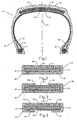
- the belt reinforcing package (23) in the illustrated embodiment comprises a high modulus reinforcing material (18) folded into a belt reinforcing package (23) wherein the high modulus reinforcing material (18) has a width about twice the width of the belt reinforcing package (23).
- the low modulus reinforcing material (19) has substantially the same width as the high modulus reinforcing material (18) and is folded completely around the folded belt reinforcing package (23).
- the low modulus reinforcing material (19a) has a width about five-eighths to seven-eighths of the width of the high modulus reinforcing material (18) and is placed radially inward of the folded belt, and the width edges of the low modulus reinforcing material (19a) are folded radially outward of the folded belt reinforcing package (23) over the folded belt edges.
- the low modulus reinforcing material (19b,19c) comprises split belt edge layers having a combined width of about five-eighths to seven-eighths of the width of the ply used to form the belt reinforcing package (23) wherein one edge of each split layer is disposed radially inward of the high modulus reinforcing material (18) and the distal end of each split layer is folded radially outward of the belt reinforcing package (23), substantially completely covering the radially outer surface of the belt reinforcing package (23).
- the high modulus reinforcement cords are aramid
- the low modulus reinforcement cords are nylon
- the high modulus reinforcement cords are disposed in a tire construction at an angle of ⁇ 15 to ⁇ 25° with respect to the equatorial plane (EP) of the tire and the low modulus reinforcement cords are aligned in the same general direction as the high modulus reinforcement cords and are disposed at an angle of ⁇ 15 to ⁇ 29° with respect to the EP of the tire.
- a method of building a belt package using the above steps is also provided.
- an aircraft tire (10) of the invention comprises a pair of parallel annular beads (12), carcass ply (13) wrapped around the beads, optional apex (22) above the bead and between the carcass ply and the carcass ply tumup, optional flipper (11) protecting the bead area, optional inner liner (14) radially inward of the carcass ply, reinforcement package (23) comprising folded belt (18) wrapped around cut belts (17) and low modulus reinforcement ply (19) wrapped around folded belt (18) disposed over carcass ply (13) in a crown area of the tire, tread (16) disposed radially above reinforcement package (23), and sidewalls (15) disposed between the tread and a bead area of the tire.
- aircraft tires are made with up to 4 pairs of beads and up to 12 carcass plies and up to 12 belt plies depending on their intended use.
- Cut belts (17) and high modulus reinforcement material (18) comprise high modulus reinforcement cords embedded in rubber. Two to five cut belts can be used in the tire of the invention. In the illustrated embodiment, three cut belts having an end count of 5,5 to 8,7 e.p.cm or ends per cm (14 to 22 e.p.i.) are used. The ply used to form high modulus reinforcement material (18) also has an end count of 5,5 to 8,7 e.p.cm (14 to 22 e.p.i.).
- the high modulus cords used in the invention may be, for example, aramid or steel, or any other high modulus material having similar properties, or a combination of such high modulus materials.
- Such reinforcement cords can comprise any suitable denier and any suitable twist.
- Such high modulus cords may be treated to increase their bond strength to rubber, and aramid reinforcement cords may be coated with an adhesive or an adhesive/epoxy combination.
- the high modulus cords used in the illustrated embodiment are 1500/3 denier aramid and have a twist of 6.9/6.9.
- cord reinforcement in the folded over part of the ply will have an equal but opposite angle with respect to the EP of the tire as the non folded over portion of the ply.
- the angle of reinforcement cords in a folded ply will be indicated with a plus/minus ( ⁇ ) in front of the angle.
- Angles of cords in other reinforcement plies in the tire will be given an absolute value, regardless of their general direction of orientation, it being understood that in most, but not all cut belt constructions, reinforcement cords in alternate cut belts are oriented in the opposite direction with respect to the EP of the tire.
- the angle of the reinforcement cords in the cut belts 17 are at an angle of 12 to 22° with respect to the EP of the tire, and reinforcement cords in alternate cut belts have the opposite angle of orientation.
- aramid cords coated with an RFL adhesive and an end count of 7,9 e.p.cm (20 e.p.i.) were used, and the ply used to form high modulus reinforcement material (18) was incorporated into the tire wherein the reinforcement cords were oriented at an angle of ⁇ 18° with respect to the EP of the tire.
- the tire is a radial ply tire wherein the reinforcement cords in the cut belts (17) are oriented at an angle of 15° with respect to the EP of the tire.
- Low modulus reinforcement material (19,19a,19b,19c) comprises low modulus reinforcement cords or filaments embedded in rubber and having an end count of 5,5 to 8,6 e.p.cm (14 to 22 e.p.i.).
- Low modulus cords or filaments of, for example, nylon can be used in the construction of low modulus reinforcement material (19,19a,19b,19c).
- Such reinforcement cords can comprise any suitable size and twist, and in the illustrated embodiment, 840/2 denier nylon cords with a twist of 12/12 were used arid incorporated in the ply at an end count of 8,3 e.p.cm (21 e.p.i.).
- the angle of the low modulus reinforcement cords or filaments in the low modulus reinforcement material (19,19a,19b,19c) may be oriented in the tire having the same angle with respect to EP as the high modulus reinforcement cords in high modulus reinforcement material (18) up to an angle 4° greater than such high modulus cords and, accordingly, may be angled at ⁇ 15 to ⁇ 29° with respect to the EP of the tire, and in the illustrated embodiment were oriented at the same angle as the reinforcement cords in high modulus reinforcement material (18).
- Tires tested according to the invention were made using cable beads and a carcass construction comprising two turn-up plies and one turndown ply. It is believed that the belt package reinforcement described will work with any conventional aircraft tire construction.
- the high modulus reinforcing material (18) and the low modulus reinforcing material (19,19a,19b,19c) is substantially two dimensional, those skilled in the art being aware that such plies are about 8 to 12 mm thick.
- the full width of the ply used to form high modulus reinforcement material (18) is 24,9 cm (9.8 inches) and the width of the ply used to form low modulus reinforcing material (19,19a,19b,19c) is 26,5 cm (10.1 inches), and the length of both plies is about 188 cm (74 inches) it being understood that the length and width can vary depending on the size of the tire and the tire construction in which the described belt reinforcement package (23) is used.
- the low modulus reinforcing material (19,19a,19b,19c) substantially covers the radially outermost surface and/or the radially innermost surface of the folded belt in addition to the folded belt edges of high modulus reinforcing material (18).
- low modulus reinforcing material (19) may be applied to fully encompass high modulus reinforcement material (18) (Fig. 2), to be placed in the tire radially below high modulus reinforcement material (18) wherein the ply ends (25) are folded around the folded ends (21) of high modulus reinforcement material (18) (Fig. 3), or provided in split layers wherein the ends 42 of low modulus reinforcement (19b,19c) radially below high modulus reinforcement material (18) cover the folded ends (21) of high modulus reinforcement material (18) and the distal ends (44) thereof are folded over high modulus reinforcement material (18) to fully encompass the radially outward portion thereof (Fig. 4).
- the ply used to form low modulus reinforcing material (19,19a,19b,19c) may have the same width or about five-eighths to seven-eighths of the width of the ply used to form high modulus reinforcement material (18).
- the various ply used to make reinforcement package (23) tend to tangle and bunch if their actual length is not adjusted to reflect their actual relationship in the tire.
- the low modulus reinforcement material (19,19a,19b,19c) is the radially innermost belt package ply in the tire
- its actual diameter in a completed tire is slightly less than the diameter of the cut belts (17) which are disposed radially above the low modulus reinforcing material (19,19a,19b,19c)
- the method of building the tires of the invention comprises the steps of, reducing the diameter of a belt building drum below that required for building a belt, applying a low modulus reinforcing material (19,19a,19b,19c) to the belt building drum, expanding the diameter of the belt building drum to a diameter which is still less than the diameter required for building a tire, applying a high modulus reinforcing material (18) over the low modulus reinforcing material (19,19a,19b,19c) on the belt building drum, expanding the diameter of the belt building drum to the diameter required for building a belt reinforcement package (23) for a tire, applying cut belts (17) over the high modulus reinforcing material (18) on the building drum, folding the high modulus reinforcing material (18) and the low modulus reinforcing material (19,19a,19b,19c) over the cut belts (17), expanding the tire carcass to the belt reinforcing package (23), and adding tread (16) and sidewalls (15) and any other external components required to complete the
- the belt reinforcing package (23) described herein may be useful in other types of tires and also provided is a method of building a belt package, said method comprising the steps for building a belt package described above.
- a low modulus reinforcing material (19,19a,19b,19c) may have a length of about 187 cm (73.5 inches)
- a ply for a folded belt comprising high modulus reinforcement (18) may have a length of about 188 cm (74 inches) and the cut belts (17) may have a length of about 189 cm (74.5 inches).
- the low modulus reinforcement material (19,19a,19b,19c) and the high modulus reinforcing material (18) are folded at the same time in the tire building procedure, and when the low modulus reinforcement material (19,19a,19b,19c) and the high modulus reinforcing material (18) are the same width, a construction where a folded high modulus reinforcement material (18) is encapsulated by a low modulus reinforcing material (19) is formed as illustrated in Fig. 2.
- a construction similar to that illustrated in Fig. 3 is obtained using the same technique. To form the construction illustrated in Fig.
- two split layers of low modulus reinforcing material (19b,19c) are applied to the building drum wherein a first end 42 of low modulus reinforcing material (19b,19c) are applied to the drum followed by application of the high modulus reinforcing material (18) to the drum, and distal ends (44) of split high modulus reinforcement material (19b,19c) are folded at the same time as the high modulus reinforcing material (18) to form high modulus reinforcement material (18) and a reinforcement package including low modulus reinforcing material (19b,19c).
- the ply used as the low modulus reinforcement material (19a) is about three-fourths as wide as the ply used to form high modulus reinforcement material (18).
- the combined width of low modulus reinforcement material (19b,19c) is about three-fourths of the width of the ply used to form high modulus reinforcement material (18).
- the folded ends (27) of the ply used to form high modulus reinforcement material (18) and ply ends (25) of low modulus reinforcement material (19,19a,19b,19c) be in abutment at the EP of the tire, but those skilled in the art will recognize that the ends (27) of the high modulus reinforcing material (18) and ends (25) of the low modulus reinforcing material (19,19a,19b,19c) can be off-set from the EP of the tire, and in some applications, the high modulus reinforcing material (18) ends (27) and low modulus reinforcing material (19,19a,19b,19c) ends (25) may be short of abutment or may form an overlap splice.
- Aircraft tires of the kind illustrated herein are qualified by a step load test where tires at a specific load are run at various increasing speed steps up to a maximum, and under an increased load are run through the speed steps again.
- Tires of the invention have been preliminarily qualified at speeds of 338 Km/h (210 mph) in a radial aircraft tire size 26x6.6R14 14PR, and it is believed that such tires will qualify at 362 Km/h (225 mph). It is believed also that retreadability will be increased substantially. It has been shown that tires of the invention show increased tread wear as compared to similarly constructed tires using nylon belt reinforcement.
Landscapes
- Engineering & Computer Science (AREA)
- Mechanical Engineering (AREA)
- Tires In General (AREA)
Claims (10)
- Flugzeugreifen (10), umfassend mindestens zwei parallele, ringförmige Wülste (12), mindestens eine Karkasslage (13), die um die Wülste (12) herumgewickelt ist, ein Gürtelverstärkungspaket (23), das ein Hochmodul-Verstärkungsmaterial (18) mit gefalteten Rändern umfasst und über der mindestens einen Karkasslage (13) in einem Kronenbereich des Reifens (10) angeordnet ist, einen Laufstreifen (16), der über dem Gürtelverstärkungspaket (23) angeordnet ist, und Seitenwände (15), die zwischen dem Laufstreifen (16) und den Wülsten (12) angeordnet sind, wobei der Reifen dadurch gekennzeichnet ist, dass das Gürtelverstärkungspaket (23) eine Schicht aus Niedermodul-Verstärkungsmaterial (19, 19a, 19b, 19c) umfasst, die um die gefalteten Ränder des Hochmodul-Verstärkungsmaterials (18) herumgewickelt ist.
- Flugzeugreifen nach Anspruch 1, wobei das Hochmodul-Verstärkungsmaterial (18) eine Breite von ungefähr der doppelten Breite des Gürtelverstärkungspakets (23) aufweist.
- Flugzeugreifen nach Anspruch 2, wobei das Niedermodul-Verstärkungsmaterial (19) im Wesentlichen die gleiche Breite wie das Hochmodul-Verstärkungsmaterial (18) aufweist und vollständig um das Hochmodul-Verstärkungsmaterial (18) herumgefaltet ist.
- Flugzeugreifen nach Anspruch 2, wobei das Niedermodul-Verstärkungsmaterial (19a) eine Breite von ungefähr fünf Achteln bis sieben Achteln der Breite des Hochmodul-Verstärkungsmaterials (18) aufweist und radial unter dem Hochmodul-Verstärkungsmaterial (18) angeordnet ist, und die Ränder des Niedermodul-Verstärkungsmaterials (19a) radial über das Hochmodul-Verstärkungsmaterial (18) gefaltet sind.
- Flugzeugreifen nach Anspruch 2, wobei das Niedermodul-Verstärkungsmaterial (19b, 19c) geteilte Gürtelrandschichten mit einer kombinierten Breite von ungefähr fünf Achteln bis sieben Achteln der Breite des Hochmodul-Verstärkungsmaterials (18) umfasst, wobei ein Rand jeder geteilten Schicht radial unter dem Hochmodul-Verstärkungsmaterial (18) angeordnet ist, und das distale Ende jeder geteilten Schicht radial über das Hochmodul-Verstärkungsmaterial (18) gefaltet ist, wobei es die radial äußere Oberfläche des Hochmodul-Verstärkungsmaterials (18) im Wesentlichen vollständig bedeckt.
- Flugzeugreifen nach Anspruch 1, wobei das Hochmodul-Verstärkungsmaterial (18) Aramid ist.
- Flugzeugreifen nach Anspruch 1, wobei das Niedermodul-Verstärkungsmaterial (19, 19a, 19b, 19c) Nylon ist.
- Flugzeugreifen nach Anspruch 1, wobei das Hochmodul-Verstärkungsmaterial (18) in einem Reifenaufbau unter einem Winkel von ±15 bis ±25° in Bezug auf die Äquatorialebene (EP) des Reifens angeordnet ist, und das Niedermodul-Verstärkungsmaterial (19, 19a, 19b, 19c) in der gleichen Hauptrichtung wie das Hochmodul-Verstärkungsmaterial (18) ausgerichtet und unter einem Winkel von ±15 bis ±29° in Bezug auf die EP des Reifens angeordnet ist.
- Verfahren zum Aufbauen eines Flugzeugreifens mit den Schritten, dass:(a) der Durchmesser einer Gürtelaufbautrommel unter denjenigen reduziert wird, der zum Aufbauen eines Gürtelverstärkungspakets (23) für einen Reifen (10) erforderlich ist,(b) ein Niedermodul-Verstärkungsmaterial (19, 19a, 19b, 19c) auf die Gürtelaufbautrommel aufgebracht wird,(c) der Durchmesser der Gürtelaufbautrommel auf einen Durchmesser ausgedehnt wird, der noch kleiner als der Durchmesser ist, der zum Aufbauen eines Gürtelverstärkungspakets (23) für einen Reifen (10) erforderlich ist,(d) ein Hochmodul-Verstärkungsmaterial (18) über dem Niedermodul-Verstärkungsmaterial (19, 19a, 19b, 19c) auf die Gürtelaufbautrommel aufgebracht wird,(e) der Durchmesser der Gürtelaufbautrommel auf den Durchmesser ausgedehnt wird, der zum Aufbauen eines Gürtelverstärkungspakets (23) für einen Reifen (10) erforderlich ist,(f) Schnittgürtel (17) über dem Hochmodul-Verstärkungsmaterial (18) aufgebracht werden,(g) das Hochmodul-Verstärkungsmaterial (18) und das Niedermodul-Verstärkungsmaterial (19, 19a, 19b, 19c) über die Schnittgürtel (17) gefaltet werden, um ein Gürtelverstärkungspaket (23) zu bilden,(h) eine Reifenkarkasse auf einer Reifenaufbautrommel bis zum Gürtelverstärkungspaket (23) ausgedehnt wird, und(i) ein Laufstreifen (16) und Seitenwände (15) und irgendwelche anderen externen Bauteile, die zur Vervollständigung des Aufbaus erforderlich sind, hinzugefügt werden.
- Verfahren zum Aufbauen eines Gürtelverstärkungspakets für einen Flugzeugreifen mit den aufeinander folgenden Schritten, dass:(a) der Durchmesser einer Gürtelaufbautrommel unter denjenigen reduziert wird, der zum Aufbauen eines Gürtelverstärkungspakets (23) für einen Reifen (10) erforderlich ist,(b) ein Niedermodul-Verstärkungsmaterial (19, 19a, 19b, 19c) auf die Gürtelaufbautrommel aufgebracht wird,(c) der Durchmesser der Gürtelaufbautrommel auf einen Durchmesser ausgedehnt wird, der noch kleiner als der Durchmesser ist, der zum Aufbauen eines Gürtelverstärkungspakets (23) für einen Reifen (10) erforderlich ist,(d) ein Hochmodul-Verstärkungsmaterial (18) über dem Niedermodul-Verstärkungsmaterial (19, 19a, 19b, 19c) auf die Gürtelaufbautrommel aufgebracht wird,(e) der Durchmesser der Gürtelaufbautrommel auf den Durchmesser ausgedehnt wird, der zum Aufbauen eines Gürtelverstärkungspakets (23) für einen Reifen (10) erforderlich ist,(f) Schnittgürtel (17) über dem Hochmodul-Verstärkungsmaterial (18) aufgebracht werden,(g) das Hochmodul-Verstärkungsmaterial (18) und das Niedermodul-Verstärkungsmaterial (19, 19a, 19b, 19c) über die Schnittgürtel (17) gefaltet werden.
Applications Claiming Priority (1)
| Application Number | Priority Date | Filing Date | Title |
|---|---|---|---|
| PCT/US1996/019055 WO1998023456A1 (en) | 1996-11-27 | 1996-11-27 | Aircraft tire with improved high speed properties |
Publications (2)
| Publication Number | Publication Date |
|---|---|
| EP0942838A1 EP0942838A1 (de) | 1999-09-22 |
| EP0942838B1 true EP0942838B1 (de) | 2002-06-05 |
Family
ID=22256209
Family Applications (1)
| Application Number | Title | Priority Date | Filing Date |
|---|---|---|---|
| EP96941508A Expired - Lifetime EP0942838B1 (de) | 1996-11-27 | 1996-11-27 | Flugzeugreifen mit verbesserten hochgeschwindigkeitseigenschaften |
Country Status (5)
| Country | Link |
|---|---|
| US (1) | US7467653B1 (de) |
| EP (1) | EP0942838B1 (de) |
| JP (1) | JP3857733B2 (de) |
| AU (1) | AU1063097A (de) |
| WO (1) | WO1998023456A1 (de) |
Families Citing this family (5)
| Publication number | Priority date | Publication date | Assignee | Title |
|---|---|---|---|---|
| US6444070B1 (en) * | 2000-11-29 | 2002-09-03 | The Goodyear Tire & Rubber Company | Method of building a tire having a segmented belt |
| US6394160B1 (en) * | 2000-11-29 | 2002-05-28 | The Goodyear Tire & Rubber Company | Tire with segmented belt |
| WO2006070570A1 (ja) * | 2004-12-27 | 2006-07-06 | Bridgestone Corporation | 空気入りタイヤ |
| EP2021192B1 (de) * | 2006-10-13 | 2012-06-13 | Société de Technologie Michelin | Verbessertes scherband |
| CN108583164A (zh) * | 2018-07-04 | 2018-09-28 | 江苏通用科技股份有限公司 | 承载型全钢子午线轮胎0°带束层胎冠肩部结构 |
Family Cites Families (9)
| Publication number | Priority date | Publication date | Assignee | Title |
|---|---|---|---|---|
| BE639433A (de) * | 1962-10-31 | |||
| US3322728A (en) * | 1963-06-17 | 1967-05-30 | Du Pont | Sulfonyl aromatic polyamides |
| DE1943842A1 (de) * | 1969-08-28 | 1971-03-18 | Metzeler Ag | Luftreifen mit Verstaerkungsguertel |
| GB1364426A (en) * | 1970-09-11 | 1974-08-21 | Dunlop Holdings Ltd | Pneumatic tyres |
| FR2462993A1 (fr) * | 1979-08-13 | 1981-02-20 | Michelin & Cie | Procede de fabrication de pneumatiques pour roues de vehicules |
| JPH01110940A (ja) * | 1987-06-26 | 1989-04-27 | Bridgestone Corp | タイヤ用ベルトの製造方法 |
| JPH01223004A (ja) * | 1988-03-01 | 1989-09-06 | Bridgestone Corp | 高内圧・重荷重用空気入りラジアルタイヤ |
| US5223061A (en) * | 1990-10-01 | 1993-06-29 | The Goodyear Tire & Rubber Company | Belt structure for a radial pneumatic tire, including spirally wound strips reinforced by cords comprising aramid yarns |
| JPH079814A (ja) * | 1993-06-29 | 1995-01-13 | Toyo Tire & Rubber Co Ltd | ラジアルタイヤ |
-
1996
- 1996-11-27 EP EP96941508A patent/EP0942838B1/de not_active Expired - Lifetime
- 1996-11-27 WO PCT/US1996/019055 patent/WO1998023456A1/en not_active Ceased
- 1996-11-27 AU AU10630/97A patent/AU1063097A/en not_active Abandoned
- 1996-11-27 US US09/297,589 patent/US7467653B1/en not_active Expired - Fee Related
- 1996-11-27 JP JP52658398A patent/JP3857733B2/ja not_active Expired - Fee Related
Also Published As
| Publication number | Publication date |
|---|---|
| AU1063097A (en) | 1998-06-22 |
| US7467653B1 (en) | 2008-12-23 |
| EP0942838A1 (de) | 1999-09-22 |
| JP2002501451A (ja) | 2002-01-15 |
| WO1998023456A1 (en) | 1998-06-04 |
| JP3857733B2 (ja) | 2006-12-13 |
Similar Documents
| Publication | Publication Date | Title |
|---|---|---|
| US4989658A (en) | Belt overlay structure for pneumatic tires comprising a single ribbon wrapped about the belt structure | |
| CA1296977C (en) | Cables and tires reinforced by said cables | |
| CA2168278C (en) | Thin gauge, fine diameter steel cord reinforced tire ply fabric and a method of lap splicing the fabric | |
| AU624223B2 (en) | Belt overlay structure for pneumatic tires | |
| EP0604807A1 (de) | Reifen mit Kohlenstoffaser-Verstärkung | |
| JPH02167736A (ja) | 帯状の積層補強体並びに空気入りタイヤ | |
| US4945967A (en) | Reinforcing armouring of tires for vehicle wheels | |
| EP0858914A2 (de) | Verstärkungsgürtel für Reifen | |
| US5007974A (en) | Method of making a belt overlay for pneumatic tires | |
| US4832103A (en) | Pneumatic tire having plural aramid carcass plies | |
| EP0942838B1 (de) | Flugzeugreifen mit verbesserten hochgeschwindigkeitseigenschaften | |
| US6546983B1 (en) | Tire with buried overlay | |
| CA1105818A (en) | Tire carcass structure | |
| EP1112869B1 (de) | Ununterbrochener, gefaltener Gürtel und Spleissung dafür | |
| US4936366A (en) | Pneumatic tire | |
| CA1280678C (en) | Pneumatic tires | |
| EP0353621A2 (de) | Metall-Kordlagen und Verwendung in Luftreifen | |
| JP2688522B2 (ja) | 空気入りタイヤ | |
| JPH11256487A (ja) | 金属コ―ド及び空気タイヤ | |
| JPH06255311A (ja) | 空気入りタイヤ | |
| EP1071567B1 (de) | Reifen mit eingebetteter gürteldecklage | |
| JPH02106406A (ja) | 空気入りラジアルタイヤ | |
| CA1324564C (en) | Pneumatic tire | |
| JPS6160301A (ja) | 重荷重用空気入りラジアルタイヤ | |
| CZ187299A3 (cs) | Letecká pneumatika a způsob její výroby |
Legal Events
| Date | Code | Title | Description |
|---|---|---|---|
| PUAI | Public reference made under article 153(3) epc to a published international application that has entered the european phase |
Free format text: ORIGINAL CODE: 0009012 |
|
| 17P | Request for examination filed |
Effective date: 19990520 |
|
| AK | Designated contracting states |
Kind code of ref document: A1 Designated state(s): FR GB |
|
| AX | Request for extension of the european patent |
Free format text: RO PAYMENT 19990520 |
|
| 17Q | First examination report despatched |
Effective date: 20001129 |
|
| GRAG | Despatch of communication of intention to grant |
Free format text: ORIGINAL CODE: EPIDOS AGRA |
|
| GRAG | Despatch of communication of intention to grant |
Free format text: ORIGINAL CODE: EPIDOS AGRA |
|
| GRAH | Despatch of communication of intention to grant a patent |
Free format text: ORIGINAL CODE: EPIDOS IGRA |
|
| GRAH | Despatch of communication of intention to grant a patent |
Free format text: ORIGINAL CODE: EPIDOS IGRA |
|
| GRAA | (expected) grant |
Free format text: ORIGINAL CODE: 0009210 |
|
| AK | Designated contracting states |
Kind code of ref document: B1 Designated state(s): FR GB |
|
| AX | Request for extension of the european patent |
Free format text: RO PAYMENT 19990520 |
|
| REG | Reference to a national code |
Ref country code: GB Ref legal event code: FG4D |
|
| ET | Fr: translation filed | ||
| PLBE | No opposition filed within time limit |
Free format text: ORIGINAL CODE: 0009261 |
|
| STAA | Information on the status of an ep patent application or granted ep patent |
Free format text: STATUS: NO OPPOSITION FILED WITHIN TIME LIMIT |
|
| 26N | No opposition filed |
Effective date: 20030306 |
|
| PGFP | Annual fee paid to national office [announced via postgrant information from national office to epo] |
Ref country code: GB Payment date: 20051004 Year of fee payment: 10 |
|
| PGFP | Annual fee paid to national office [announced via postgrant information from national office to epo] |
Ref country code: FR Payment date: 20051104 Year of fee payment: 10 |
|
| GBPC | Gb: european patent ceased through non-payment of renewal fee |
Effective date: 20061127 |
|
| REG | Reference to a national code |
Ref country code: FR Ref legal event code: ST Effective date: 20070731 |
|
| PG25 | Lapsed in a contracting state [announced via postgrant information from national office to epo] |
Ref country code: GB Free format text: LAPSE BECAUSE OF NON-PAYMENT OF DUE FEES Effective date: 20061127 |
|
| PG25 | Lapsed in a contracting state [announced via postgrant information from national office to epo] |
Ref country code: FR Free format text: LAPSE BECAUSE OF NON-PAYMENT OF DUE FEES Effective date: 20061130 |