EP0942190B1 - Ausrückevorrichtung, insbesondere für eine Kupplung - Google Patents
Ausrückevorrichtung, insbesondere für eine Kupplung Download PDFInfo
- Publication number
- EP0942190B1 EP0942190B1 EP99104690A EP99104690A EP0942190B1 EP 0942190 B1 EP0942190 B1 EP 0942190B1 EP 99104690 A EP99104690 A EP 99104690A EP 99104690 A EP99104690 A EP 99104690A EP 0942190 B1 EP0942190 B1 EP 0942190B1
- Authority
- EP
- European Patent Office
- Prior art keywords
- disengaging
- disengaging device
- force
- energy
- energy storage
- Prior art date
- Legal status (The legal status is an assumption and is not a legal conclusion. Google has not performed a legal analysis and makes no representation as to the accuracy of the status listed.)
- Expired - Lifetime
Links
Images


Classifications
-
- F—MECHANICAL ENGINEERING; LIGHTING; HEATING; WEAPONS; BLASTING
- F16—ENGINEERING ELEMENTS AND UNITS; GENERAL MEASURES FOR PRODUCING AND MAINTAINING EFFECTIVE FUNCTIONING OF MACHINES OR INSTALLATIONS; THERMAL INSULATION IN GENERAL
- F16D—COUPLINGS FOR TRANSMITTING ROTATION; CLUTCHES; BRAKES
- F16D25/00—Fluid-actuated clutches
- F16D25/12—Details not specific to one of the before-mentioned types
Definitions
- the present invention relates to a release device, in particular for a clutch.
- Such, generic release device is z. B. from DE 38 06 642 A1.
- This release device has an energy storage, which emits energy when disengaged and energy stores in an opposite process on.
- As an energy store in this case serve two perpendicular to a release piston arranged springs, which interact with a serving as a power coupler roller bearing, which is guided along a substantially conical cam track on the release piston, with the release piston.
- an assembly carrying the cam track can be displaced along the disengaging piston, whereby clutch wear can be independently taken into account. The displacement of this assembly is proportional to the path of the release piston.
- a release device in particular for a clutch to provide, which is very compact and yet allows the setting of favorable power ratios.
- the invention proposes a release device according to claim 1.
- a particularly simple and also favorable from the distribution of forces disengagement device follows when the energy storage, which is to be acted upon in a preferred direction with a force, and a substantially movable along one direction drive such that these two directions are aligned substantially parallel to each other are.
- Such a compact arrangement allows particularly short distances, on the one hand for the energy-increasing means, on the other hand, but also for a possibly necessary force deflection.
- Such short distances require on the one hand a small volume and on the other hand allow a favorable implementation of the forces occurring in the release device.
- the energy increase is proportional to the force occurring in the release device. This means that at a higher power the energy storage more energy is supplied.
- the arrangement is constructed such that energy is supplied to the energy store when the force occurring in the disengaging device or a pressure proportional thereto exceeds a corresponding value applied by the energy store.
- a simple realization of such an arrangement can take place in that the means for increasing the energy comprise a provided with a check valve hydraulic arrangement.
- This hydraulic arrangement can use a corresponding piston energy bring in the energy storage, while the check valve prevents a backflow of energy when the force occurring in the release device is reduced.
- a particularly uncomplicated arrangement follows when the release device itself comprises a hydraulic system and the hydraulic arrangement which serves to increase the energy is driven by this hydraulic system of the release device.
- the inventive arrangement allows due to their means for increasing the energy in the energy storage in response to a Force occurring in the release device a corresponding increase in energy in the energy storage. This means that the force released by the energy storage force relief over the life of the clutch takes place with a constant factor.
- this factor can be made variable. This can be z. B. done so that the power relief with increasing clutch wear also increases, so that the corresponding proportional increase in the operating pressure can be counteracted and necessary for the actuation of the clutch force over the life remains almost constant.
- Such a function implementing means may, for. B. compensation springs.
- disc springs can be used directly as compensation springs, which exert a greater force at low deflection than at greater deflection. If such disc springs are directly opposite to the force occurring in the release device, these counteract the system pressure in the new state of the clutch with a large force and with a worn clutch with a lower force.
- a disengaging device in which the energy store is coupled to the rest of the disengaging device by means of a force coupler guided along a curved path, preferably a roller bearing rolling along the curved path, means for force deflection can advantageously be provided between the energy store and the force coupler.
- the energy storage can be arranged as space-saving as possible, for example, parallel to a release piston.
- Such force deflection can z.
- this spring can be arranged around the drive. This allows the use of a relatively large spring with the corresponding properties of a large spring for energy storage.
- the directions can be defined by any coordinate in arbitrary coordinate systems.
- these directions can be selected in parallel in cylindrical coordinates or Cartesian coordinates, which means that the directions can be selected in particular radially, axially or linearly.
- the abovementioned features of the disengaging device according to the invention are particularly suitable for a disengaging device which comprises a substantially linearly driven disengaging piston or a similar drive.
- the features according to the invention can be used advantageously in any type of disengaging device.
- the term releasing device comprises any assembly that is statically or movably involved in a disengaging process, individually or in combination with further subassemblies, which may likewise be involved in the disengaging process.
- the disengagement device is connected only indirectly via a coupling member, such as a hydraulic connection, with the assembly to be removed.
- the coupling member ensures a certain independence from the ausugurenden assembly such.
- the disengaging device can be arranged directly on a clutch or operating pedal or lever.
- the coupling member then provides the corresponding force connection from the release device to the assembly to be removed, such. B. the clutch itself.
- the balance of power can be selected on the release device largely independent of the forces occurring on the coupling or the assembly ausugurenden force.
- the energy storage can be used independently of other, possibly complementary measures on the clutch itself to facilitate the Ausgurearbeit to be performed.
- the release device can be structurally simple compact, if it comprises at least one roller, which is guided by means of a guide surface and an operatively connected to the energy storage bevel and interacts with a contour of the drive.
- the slope and the contour are guided in opposite directions substantially in opposite directions.
- a coaxial alignment of the release drive and the energy storage can be realized in a simple manner.
- the radii of the contour contacting portions and the tapered portions of the roller are selected so that the roller can roll on both surfaces at approximately the same speed. In this way, a virtually slip-free power deflection is ensured.
- the roller has at least two mutually rotatably mounted assemblies, one of which rests on the slope and the other on the contour. In this way, any existing slip is transferred to the roller itself. This can be counteracted there with smaller radii and thus lower forces.
- the roller may have at least one guide body rotatably mounted on the roller, which is guided on the guide surface. In this way, a friction occurring at this point is advantageously reduced.
- the energy storage comprises a mechanical energy storage, such as a spring.
- the energy store may comprise an axially arranged to drive the release device spring. If this spring is arranged coaxially to the drive, a particularly compact embodiment of the disengagement device follows.
- the drive can represent any push or lift linkage which is moved along at least one component along its longitudinal direction.
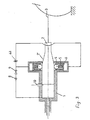
- the release device comprises a clutch master cylinder 1 of a hydraulic clutch actuation, in which a piston 2 can establish a disengaging pressure.
- the piston 2 is actuated by a clutch pedal rod 3, which is operatively connected to a corresponding clutch pedal.
- the cylinder 1 is sealed by seals 11 and 12 and surrounded by a housing part 16.
- the disengaging device has a further housing part 17, which is connected to the housing part 16 by a flared connection.
- a bellows 18 which is arranged between the housing part 17 and the clutch pedal rod 3, the housing 16; 17 completely closed.
- the piston 2 has at its pedal end a contour 2 '. On this contour 2 'run rollers 4, which are biased by springs 5. Between the springs 5 and the rollers 4, which serve as a power coupler means are provided for power deflection. These include a force deflection ring 14 with a slope and a disc 15 with a guide surface. By the springs 5, the slope and the guide surface, the rollers 4 are biased such that they exert a force radially inward on the contour 2 '. When the clutch pedal is stepped on, the rollers 4 can shift in the direction of the clutch pedal rod 3. As a result, the force deflecting ring 14 moves counter to the actuating direction of the clutch pedal rod 3. In this process, the springs relax 5 and give an appropriate work on the piston 2 from. If the clutch is engaged again, pushes a plate spring of the clutch, or something similar, the piston 2 in its initial position, and the spring 5 is stretched again.
- the rollers 4 comprise, as shown in particular in Figure 2, rollers 21 which are guided on an axis 20.
- rollers 21 which are guided on an axis 20.
- the radii of the rollers 21 and the shafts 20 are selected according to an inclination angle of 45 ° of the slope in a ratio of 1: ⁇ 2, so that an approximately slip-free movement of the rollers 4 can be ensured, even if the axes 20 and the rollers 21 are firmly connected.
- the axis 20 and the roller 21 are not made in one piece and mutually rotatable.
- the diameter of these plastic discs 19 is selected to be slightly larger than the diameter of the rollers 21. In this way, the plastic discs 19 are supported on the guide surface of the disc 15, while each of the rollers 21 is not hindered by the disc 15.
- the diameter of the plastic discs is chosen so small that they are not hindered in their rotation by the contour 2 '. Such a formation is, as shown in Figure 2, possible because of the circular cross-section of the contour 2 '.
- the spring 5 is supported on a piston 6, which in turn is subjected to a system pressure of the hydraulic clutch actuation from the cylinder 1.
- the pressure in the cylinder 1 is removed and fed to the piston 6 via a check valve 8 and a calibrated throttle 9.
- disc springs in this case has the immediate advantage that they can be designed so that they exert a larger force at low deflection than at greater deflection and thus the hydraulic pressure in the new condition of the clutch, a large force is opposed, while in worn clutch the System pressure is opposed by a lower force.
- the check valve 8 causes the pressure on the piston 6 and thus the bias of the spring 5 is maintained at its maximum value.
- the throttle allows disengagement even if after a longer service life, the pressure on the piston 6 has been lost. After a few dome operations, the necessary pressure is restored.
- the release device further comprises a vent 22, which allows relief of the hydraulic system when replacing the clutch or changing the clutch linings.
- the piston 6 further covers a sniffer bore, which is connected to a vent 10 of the hydraulic system. In this way, it is ensured that the piston 6 can not be moved beyond this sniffer bore.
- the driven by the cylinder 1 hydraulics allows as a coupling member further advantageous structural independence of the release device to the clutch itself.
- the housing 16, 17 is further provided with tabs 13, which serve to attach the release device.
- the inner diameter of the disc 15 is selected so narrow that the contour 2 ', the disc 15 can not penetrate. This serves as an assembly aid during assembly of this release device.
- FIGS. 3 to 5 The exemplary embodiment illustrated in FIGS. 3 to 5 is not quite as compact as the exemplary embodiment described above. In essence, however, it is constructed the same as the previously described embodiment. Identical modules are numbered the same in both embodiments.
- the second disengagement device has two springs 5 arranged on both sides of the piston 2. These are in the present embodiment perpendicular to the piston 2 and thus perpendicular to the drive of Release device to apply a force. It is understood that with a roller guide or the like shown with reference to the first embodiment, this preferred direction can be changed in the desired manner without further notice. Likewise, the hydraulic lines are arranged for the means for increasing energy within the housing, so that these release device compact builds compared to known release devices.
- the springs 5 are compressed in the worn state by the increased system pressure, so that in the springs 5, so the energy storage, a higher energy is stored, which can be used to facilitate Ausschreibearbeit.
Landscapes
- Engineering & Computer Science (AREA)
- General Engineering & Computer Science (AREA)
- Mechanical Engineering (AREA)
- Hydraulic Clutches, Magnetic Clutches, Fluid Clutches, And Fluid Joints (AREA)
- Mechanical Operated Clutches (AREA)
- Arrangement And Mounting Of Devices That Control Transmission Of Motive Force (AREA)
Applications Claiming Priority (6)
| Application Number | Priority Date | Filing Date | Title |
|---|---|---|---|
| DE19810955 | 1998-03-13 | ||
| DE19810955 | 1998-03-13 | ||
| DE19817904 | 1998-04-22 | ||
| DE19817904 | 1998-04-22 | ||
| DE19828198A DE19828198A1 (de) | 1998-03-13 | 1998-06-25 | Ausrückevorrichtung, insbesondere für eine Kupplung |
| DE19828198 | 1998-06-25 |
Publications (3)
| Publication Number | Publication Date |
|---|---|
| EP0942190A2 EP0942190A2 (de) | 1999-09-15 |
| EP0942190A3 EP0942190A3 (de) | 2001-01-24 |
| EP0942190B1 true EP0942190B1 (de) | 2006-05-31 |
Family
ID=27218209
Family Applications (1)
| Application Number | Title | Priority Date | Filing Date |
|---|---|---|---|
| EP99104690A Expired - Lifetime EP0942190B1 (de) | 1998-03-13 | 1999-03-10 | Ausrückevorrichtung, insbesondere für eine Kupplung |
Country Status (4)
| Country | Link |
|---|---|
| US (1) | US6213271B1 (ja) |
| EP (1) | EP0942190B1 (ja) |
| JP (1) | JP4358346B2 (ja) |
| DE (1) | DE59913473D1 (ja) |
Families Citing this family (7)
| Publication number | Priority date | Publication date | Assignee | Title |
|---|---|---|---|---|
| DE19943339A1 (de) * | 1999-09-10 | 2001-03-15 | Rohs Voigt Patentverwertungsge | Ausrückevorrichtung, insbesondere für eine Kupplung |
| EP1094234A3 (de) * | 1999-10-22 | 2002-03-13 | ZF Sachs AG | Ausrückvorrichtung |
| JP4542307B2 (ja) * | 2002-10-18 | 2010-09-15 | アイシン精機株式会社 | クラッチ制御装置 |
| US20060213748A1 (en) * | 2005-03-26 | 2006-09-28 | Luk Lamellen Und Kupplungsbau Beteiligungs Kg | Hydraulic clutch actuation system |
| FR2885657B1 (fr) * | 2005-05-11 | 2007-06-29 | Valeo Embrayages | Dispositif pour l'assistance au deplacement d'un moyen d'actionnement et ensemble d'assistance pour systeme de commmande d'embrayage, notamment de vehicule automobile |
| GB0817499D0 (en) * | 2008-09-24 | 2008-10-29 | Ricardo Uk Ltd | Assist mechanism for a clutch control system |
| JP6711858B2 (ja) * | 2018-04-03 | 2020-06-17 | 本田技研工業株式会社 | クラッチスレーブシリンダの組付け構造 |
Family Cites Families (12)
| Publication number | Priority date | Publication date | Assignee | Title |
|---|---|---|---|---|
| US811422A (en) * | 1905-01-19 | 1906-01-30 | William Harrison | Friction-clutch. |
| FR1586097A (ja) | 1964-07-08 | 1970-02-06 | ||
| DE2440039C2 (de) | 1974-08-21 | 1983-07-14 | Robert Bosch Gmbh, 7000 Stuttgart | Steuereinrichtung für die Kupplung eines Kraftfahrzeugs |
| DE3327057A1 (de) * | 1982-07-20 | 1985-02-14 | FAG Kugelfischer Georg Schäfer KGaA, 8720 Schweinfurt | Einrichtung zur betaetigungskraft-verstaerkung fuer die kupplungen von kraftfahrzeugen |
| IN161424B (ja) * | 1983-05-12 | 1987-11-28 | Westinghouse Brake & Signal | |
| DE3706849A1 (de) | 1987-03-03 | 1988-09-15 | Sachs Systemtechnik Gmbh | Stelleinrichtung, insbesondere fuer eine kraftfahrzeugreibungskupplung |
| DE3806642A1 (de) * | 1988-03-02 | 1989-09-14 | Kugelfischer G Schaefer & Co | Hydraulisch betaetigbare kupplung |
| DE3907341A1 (de) * | 1989-03-08 | 1990-09-13 | Schaeffler Waelzlager Kg | Kupplungsbetaetigungsvorrichtung |
| DE3930980A1 (de) | 1989-09-16 | 1991-03-28 | Autoflug Gmbh | Ausloesevorrichtung fuer einen mechanischen energiespeicher |
| DE4001473A1 (de) | 1990-01-19 | 1991-07-25 | Audi Ag | Vorrichtung an einer kupplungsbetaetigung in einem kraftfahrzeug |
| DE19700935A1 (de) | 1996-01-31 | 1997-08-07 | Luk Getriebe Systeme Gmbh | Vorrichtung zur Betätigung eines Aggregates im Antriebsstrang eines Kraftfahrzeuges |
| DE19722591A1 (de) * | 1997-05-30 | 1998-12-03 | Abb Daimler Benz Transp | Kraftspeicher |
-
1999
- 1999-03-10 DE DE59913473T patent/DE59913473D1/de not_active Expired - Lifetime
- 1999-03-10 EP EP99104690A patent/EP0942190B1/de not_active Expired - Lifetime
- 1999-03-12 JP JP06715199A patent/JP4358346B2/ja not_active Expired - Fee Related
- 1999-03-15 US US09/268,114 patent/US6213271B1/en not_active Expired - Fee Related
Also Published As
| Publication number | Publication date |
|---|---|
| EP0942190A3 (de) | 2001-01-24 |
| JP4358346B2 (ja) | 2009-11-04 |
| US6213271B1 (en) | 2001-04-10 |
| EP0942190A2 (de) | 1999-09-15 |
| DE59913473D1 (de) | 2006-07-06 |
| JPH11336792A (ja) | 1999-12-07 |
Similar Documents
| Publication | Publication Date | Title |
|---|---|---|
| EP1244879B1 (de) | Zuspanneinrichtung für radbremsen | |
| DE2326760A1 (de) | Ausrueckvorrichtung fuer kupplungen | |
| DE1450882B1 (de) | Planetengetriebe mit Doppelkupplung | |
| DE69501874T2 (de) | Von einem elektromotor gesteuerte steuervorrichtung mit hydraulischem zylinder, insbesondere für eine kraftfahrzeugkupplung | |
| DE102016012865A1 (de) | Selbstjustierender pneumatischer Kupplungsaktor | |
| DE19851668A1 (de) | Radbremsvorrichtung | |
| DE102017001410A1 (de) | Selbstjustierender pneumatischer Kupplungsaktor | |
| EP0425773A2 (de) | Betätigungsvorrichtung für einen Werkzeug- oder Werkstückspanner in einer Werkzeugmaschinenspindel | |
| DE19529791C2 (de) | Bremsaktor mit Nachstellvorrichtung | |
| DE3046669A1 (de) | Mechanische schnell-loeseeinrichtung fuer federspeicher-bremszylinder | |
| EP0942190B1 (de) | Ausrückevorrichtung, insbesondere für eine Kupplung | |
| EP1083357B1 (de) | Ausrückevorrichtung, insbesondere für eine Kupplung | |
| DE69007402T2 (de) | Gestänge zur Kraftübertragung für Kraftfahrzeuge. | |
| DE102014204174B4 (de) | Drehmomentbegrenzende Rücklaufsperre | |
| DE19736557C5 (de) | Reibungskupplung, insbesondere für Kraftfahrzeuge | |
| EP2673523B1 (de) | Vorrichtung mit einer rastmechanik | |
| DE19841346A1 (de) | Stufenlos verstellbares Kegelscheibenumschlingungsgetriebe, insbesondere für Kraftfahrzeuge | |
| DE19828198A1 (de) | Ausrückevorrichtung, insbesondere für eine Kupplung | |
| DE7411298U (de) | Federbremsbetätigungsvorrichtung | |
| DE1780442C3 (ja) | ||
| EP0881134A2 (de) | Kraftspeicher | |
| DE19521205C2 (de) | Walzenpaar einer Walzenpresse | |
| DE4025213A1 (de) | Betaetigungsvorrichtung fuer eine trennkupplung | |
| EP0950826B1 (de) | Betätigung für eine axial wirksame Kupplungsdruckplatte sowie dementsprechende Ausrückeeinheit | |
| DE3301317A1 (de) | Bremszylinder |
Legal Events
| Date | Code | Title | Description |
|---|---|---|---|
| PUAI | Public reference made under article 153(3) epc to a published international application that has entered the european phase |
Free format text: ORIGINAL CODE: 0009012 |
|
| AK | Designated contracting states |
Kind code of ref document: A2 Designated state(s): DE FR GB IT SE |
|
| AX | Request for extension of the european patent |
Free format text: AL;LT;LV;MK;RO;SI |
|
| PUAL | Search report despatched |
Free format text: ORIGINAL CODE: 0009013 |
|
| AK | Designated contracting states |
Kind code of ref document: A3 Designated state(s): AT BE CH CY DE DK ES FI FR GB GR IE IT LI LU MC NL PT SE |
|
| AX | Request for extension of the european patent |
Free format text: AL;LT;LV;MK;RO;SI |
|
| RIC1 | Information provided on ipc code assigned before grant |
Free format text: 7F 16D 23/12 A, 7F 16D 25/12 B |
|
| 17P | Request for examination filed |
Effective date: 20010511 |
|
| AKX | Designation fees paid |
Free format text: DE FR GB IT SE |
|
| 17Q | First examination report despatched |
Effective date: 20050429 |
|
| GRAP | Despatch of communication of intention to grant a patent |
Free format text: ORIGINAL CODE: EPIDOSNIGR1 |
|
| GRAS | Grant fee paid |
Free format text: ORIGINAL CODE: EPIDOSNIGR3 |
|
| GRAA | (expected) grant |
Free format text: ORIGINAL CODE: 0009210 |
|
| AK | Designated contracting states |
Kind code of ref document: B1 Designated state(s): DE FR GB IT SE |
|
| PG25 | Lapsed in a contracting state [announced via postgrant information from national office to epo] |
Ref country code: IT Free format text: LAPSE BECAUSE OF FAILURE TO SUBMIT A TRANSLATION OF THE DESCRIPTION OR TO PAY THE FEE WITHIN THE PRESCRIBED TIME-LIMIT;WARNING: LAPSES OF ITALIAN PATENTS WITH EFFECTIVE DATE BEFORE 2007 MAY HAVE OCCURRED AT ANY TIME BEFORE 2007. THE CORRECT EFFECTIVE DATE MAY BE DIFFERENT FROM THE ONE RECORDED. Effective date: 20060531 |
|
| REG | Reference to a national code |
Ref country code: GB Ref legal event code: FG4D Free format text: NOT ENGLISH |
|
| REF | Corresponds to: |
Ref document number: 59913473 Country of ref document: DE Date of ref document: 20060706 Kind code of ref document: P |
|
| PG25 | Lapsed in a contracting state [announced via postgrant information from national office to epo] |
Ref country code: SE Free format text: LAPSE BECAUSE OF FAILURE TO SUBMIT A TRANSLATION OF THE DESCRIPTION OR TO PAY THE FEE WITHIN THE PRESCRIBED TIME-LIMIT Effective date: 20060831 |
|
| GBT | Gb: translation of ep patent filed (gb section 77(6)(a)/1977) |
Effective date: 20060921 |
|
| ET | Fr: translation filed | ||
| PLBE | No opposition filed within time limit |
Free format text: ORIGINAL CODE: 0009261 |
|
| STAA | Information on the status of an ep patent application or granted ep patent |
Free format text: STATUS: NO OPPOSITION FILED WITHIN TIME LIMIT |
|
| 26N | No opposition filed |
Effective date: 20070301 |
|
| REG | Reference to a national code |
Ref country code: GB Ref legal event code: 732E |
|
| REG | Reference to a national code |
Ref country code: FR Ref legal event code: TP |
|
| PGFP | Annual fee paid to national office [announced via postgrant information from national office to epo] |
Ref country code: IT Payment date: 20100322 Year of fee payment: 12 Ref country code: FR Payment date: 20100408 Year of fee payment: 12 |
|
| PGFP | Annual fee paid to national office [announced via postgrant information from national office to epo] |
Ref country code: GB Payment date: 20100317 Year of fee payment: 12 |
|
| PGFP | Annual fee paid to national office [announced via postgrant information from national office to epo] |
Ref country code: DE Payment date: 20100430 Year of fee payment: 12 |
|
| GBPC | Gb: european patent ceased through non-payment of renewal fee |
Effective date: 20110310 |
|
| REG | Reference to a national code |
Ref country code: FR Ref legal event code: ST Effective date: 20111130 |
|
| PG25 | Lapsed in a contracting state [announced via postgrant information from national office to epo] |
Ref country code: FR Free format text: LAPSE BECAUSE OF NON-PAYMENT OF DUE FEES Effective date: 20110331 Ref country code: DE Free format text: LAPSE BECAUSE OF NON-PAYMENT OF DUE FEES Effective date: 20111001 |
|
| REG | Reference to a national code |
Ref country code: DE Ref legal event code: R119 Ref document number: 59913473 Country of ref document: DE Effective date: 20111001 |
|
| PG25 | Lapsed in a contracting state [announced via postgrant information from national office to epo] |
Ref country code: GB Free format text: LAPSE BECAUSE OF NON-PAYMENT OF DUE FEES Effective date: 20110310 Ref country code: IT Free format text: LAPSE BECAUSE OF NON-PAYMENT OF DUE FEES Effective date: 20110310 |