EP0941947B1 - Schüttgutbehälter mit einer um eine Achse schwenkbaren Öffnungsklappe - Google Patents
Schüttgutbehälter mit einer um eine Achse schwenkbaren Öffnungsklappe Download PDFInfo
- Publication number
- EP0941947B1 EP0941947B1 EP99104227A EP99104227A EP0941947B1 EP 0941947 B1 EP0941947 B1 EP 0941947B1 EP 99104227 A EP99104227 A EP 99104227A EP 99104227 A EP99104227 A EP 99104227A EP 0941947 B1 EP0941947 B1 EP 0941947B1
- Authority
- EP
- European Patent Office
- Prior art keywords
- opening
- opening flap
- narrow side
- flap
- seal
- Prior art date
- Legal status (The legal status is an assumption and is not a legal conclusion. Google has not performed a legal analysis and makes no representation as to the accuracy of the status listed.)
- Expired - Lifetime
Links
- 239000013590 bulk material Substances 0.000 title description 20
- 238000007789 sealing Methods 0.000 claims description 45
- 230000001154 acute effect Effects 0.000 claims description 11
- 239000004566 building material Substances 0.000 claims description 4
- 238000006073 displacement reaction Methods 0.000 claims description 3
- 239000000203 mixture Substances 0.000 claims description 2
- 238000007493 shaping process Methods 0.000 claims 1
- 230000000694 effects Effects 0.000 description 8
- 238000000034 method Methods 0.000 description 7
- 238000004140 cleaning Methods 0.000 description 3
- 230000006835 compression Effects 0.000 description 3
- 238000007906 compression Methods 0.000 description 3
- 239000000463 material Substances 0.000 description 3
- 238000004519 manufacturing process Methods 0.000 description 2
- 238000007790 scraping Methods 0.000 description 2
- 230000006978 adaptation Effects 0.000 description 1
- 239000000853 adhesive Substances 0.000 description 1
- 230000001070 adhesive effect Effects 0.000 description 1
- 230000009286 beneficial effect Effects 0.000 description 1
- 230000015572 biosynthetic process Effects 0.000 description 1
- 239000000470 constituent Substances 0.000 description 1
- 208000018459 dissociative disease Diseases 0.000 description 1
- 230000002349 favourable effect Effects 0.000 description 1
- 230000005484 gravity Effects 0.000 description 1
- 230000003993 interaction Effects 0.000 description 1
- 238000010008 shearing Methods 0.000 description 1
Images

Classifications
-
- B—PERFORMING OPERATIONS; TRANSPORTING
- B28—WORKING CEMENT, CLAY, OR STONE
- B28C—PREPARING CLAY; PRODUCING MIXTURES CONTAINING CLAY OR CEMENTITIOUS MATERIAL, e.g. PLASTER
- B28C7/00—Controlling the operation of apparatus for producing mixtures of clay or cement with other substances; Supplying or proportioning the ingredients for mixing clay or cement with other substances; Discharging the mixture
- B28C7/0046—Storage or weighing apparatus for supplying ingredients
- B28C7/0053—Storage containers, e.g. hoppers, silos, bins
- B28C7/0076—Parts or details thereof, e.g. opening, closing or unloading means
-
- B—PERFORMING OPERATIONS; TRANSPORTING
- B01—PHYSICAL OR CHEMICAL PROCESSES OR APPARATUS IN GENERAL
- B01F—MIXING, e.g. DISSOLVING, EMULSIFYING OR DISPERSING
- B01F35/00—Accessories for mixers; Auxiliary operations or auxiliary devices; Parts or details of general application
- B01F35/45—Closures or doors specially adapted for mixing receptacles; Operating mechanisms therefor
- B01F35/451—Closures or doors specially adapted for mixing receptacles; Operating mechanisms therefor by rotating them about an axis parallel to the plane of the opening
-
- B—PERFORMING OPERATIONS; TRANSPORTING
- B01—PHYSICAL OR CHEMICAL PROCESSES OR APPARATUS IN GENERAL
- B01F—MIXING, e.g. DISSOLVING, EMULSIFYING OR DISPERSING
- B01F35/00—Accessories for mixers; Auxiliary operations or auxiliary devices; Parts or details of general application
- B01F35/75—Discharge mechanisms
- B01F35/751—Discharging by opening a gate, e.g. using discharge paddles
Definitions
- the invention relates to a bulk container, according to the preamble of claim 1.
- Such a bulk container is known from DE 344 691 C.
- On the emptying opening has a downward-pointing nozzle inside crowned surface in cross section required what an elaborate production means.
- the container is still not a complete seal possible.
- Another bulk container with discharge opening and swiveling Opening flap is from EP 0 142 003 B2 - there as a batch mixer - already known. It is envisaged that the between the first Narrow side and the outside of the opening flap formed angle is an acute angle with the aim of being open and accordingly flap hanging down on this upper first narrow side no bulk goods should be able to remain because of this slant Narrow side slips. In one embodiment, this Previous publication, this angle is chosen so that the between the first narrow side of the opening flap and the corresponding housing wall joint in the closed position approximately runs horizontally and its cross-section approximately to the middle of the Axis of rotation is directed.
- the bulk goods container is also intended for bulk goods be suitable that contain powdery or dusty components or consist of such.
- the bulk container is for the majority of bulk materials, especially those that are powdery or contain dusty constituents or from such exist, suitable.
- the seal gradually as the counter surface closes is under increasing pressure because the counter surface and the sealing surface is not at a right angle in the sense approach that one surface after a touch the seal overall compressed, but because of the oblique and gradual approximation also the compression of the seal in the course the pivoting increases in the closed position.
- the seal will because of this arrangement not directly from each other approaching surfaces compressed, as is the case with the seal.
- EP 0 142 003 B1 is provided, but it can even be on the Seal adhering material first through the closing process be scraped off, the further course of the closing movement the seal increasingly from the scraping counter surface is acted upon and compressed.
- the pressure force transverse to the closing direction and not in the closing direction This means that practically no bulk material can adhere to the sealing surface and impair the sealing effect. Practically takes place at Seal an automatic self-cleaning of the sealing area.
- the oblique first narrow side of the opening flap can, in cross section seen with the inside enclosing an acute angle, its edge when pivoting in the closed position as a scraper serves at least on the counter slope.
- the slant of the first narrow side that with the outer surface encloses an obtuse angle, so it can go to the inside be continued that there is a corresponding acute angle is formed, the edge of which is suitable as a scraper of bulk material is, possibly in the area of the emptying opening on its edge or Narrow side stuck.
- the narrow side adjacent to the opening flap is an advantage because the Pinching foreign objects at this point in parallel running edge of such an opening flap corresponding to the The gap of this edge would gap significantly further.
- An embodiment of the invention can consist in that the parallel to the first narrow side close to the swivel axis second narrow side of the opening flap one at an angle to Outside of the flap, especially the circle has an approximate cross-sectional shape, that of it when pivoting is described about the pivot axis, and that that of the second Counter slopes at the narrow side in the closed position Emptying opening or one at another opening flap has a suitable, approximately parallel cross-sectional shape. Consequently can also on this second narrow side remote from the pivot axis jamming of bulk goods can be prevented, which is a would have significantly less impact, but still one Leakage could result. Also in the area of the second narrow side can be ensured that evt1. adhering bulk material at Closing process is automatically stripped at least to the extent that the closing process itself is not hindered.
- the second narrow side with the Outside of the opening flap - seen in cross section - one blunt and point with the inside of the opening flap Includes angle and that between the narrow side and the The inside edge serves as a scraper. While closing Such a bulk container is first the inner edge of the first narrow side its stripping function begin while stripping on the second narrow side during the very last part of the closing movement, so that those that may result from such stripping operations Resistances do not occur simultaneously.
- a particularly effective and for stripping bulk goods on the one hand and the tightest possible closure on the other favorable arrangement in a particularly simple embodiment can be that the cross section of the first narrow side and / or the second narrow side of a tangent to the respective swing circle or swing cylinder of these narrow sides corresponds to the pivot axis of the opening flap and the Narrow side (s) is (are) essentially flat.
- Such cases only need only one level overall To be trained on narrow sides, but on which nevertheless inventive advantageous stripping effect can be generated.
- the narrow side (s) and / or the counter bevel (s) has a polygonal shape, and for such polygonal shape of their cross-section at least two planar areas at an angle to one another can be provided, between which an obtuse angle is enclosed.
- the seal on the outside of the container and its sealing surface approximately in continuation of the Counter slopes of the discharge opening is arranged and the opening flap in continuation of its narrow side on the outside an approximately parallel running to the narrow side, with a blunt in cross section Angle-forming stop bar to interact with this seal has, the pressure surface facing the seal in cross section seen in the position of use in particular somewhat obliquely to the Sealing surface of the seal runs and the seal in this Use position somewhat suppressed.
- the bevel of the printing area is chosen relative to the sealing surface of the seal so that the greatest compression of the seal at the top edge region facing away from the container, that is, in The closed position takes the pressure between the pressure surface and the sealing surface seen from the container with increasing distance from its Outside too. This arrangement enables the closing process the sealing surface first shabby and then more and more with it Pressurize, but without two in the area of Seal directly approaching and pinching the seal Need surfaces so that no bulk material on the seal, impairing them, can be pinched.
- the seal can be designed as a sealing strip, the sealing surface with a relaxed, non-loaded seal, i.e. when the Opening flap is in the open position, runs essentially flat and this sealing strip can preferably from the sealing surface and one of these neighboring displacement areas entirely or partially enclosed by a support housing.
- the seal can not avoid, but is replaced by the sliding and thereby increasing pressure through the pressure surface of the Stop bar is gradually compressed and can be adjusted accordingly exert a good sealing effect.
- the support housing together with the seal adjustable with this transverse to the longitudinal extent of the seal and adjustable, especially towards the opening flap is adjustable.
- the The seal can always be moved into a position in which an optimal sealing effect is achieved.
- from assembly easier from the start because the seal with your Support housing pre-assembled and then on the opening flap and their counter surface can be adjusted.
- the emptying opening can be shaped appropriately and that in the area this approximately at right angles narrow sides Seals are provided on the outside on the edge of the emptying openings can be, which with counter surfaces inclined relative to them in cooperate in the sense that when you close the opening flap are increasingly compressible by this relative inclination.
- these can also run transversely to the pivot axis Narrow sides the beneficial sealing effect and self-cleaning the seal can be achieved through the corresponding narrow sides.
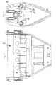
- a container designated as a whole with 1 serves for receiving and in the exemplary embodiment also for mixing bulk material and is in in this case approximately drum-shaped or cylindrical.
- These opening flap (s) 2 (18) practically form a lower one Wall area of the container 1.
- the Container 1 instead of such an approximately cylindrical container 1, the Container 1 but also any other shapes, for example have the shape of a stand silo.
- the respective opening flap 2 can be pivoted about a pivot axis 3 and has a substantially rectangular shape in the exemplary embodiments Shape, being due to the cylindrical shape of the container 1 in addition also has a curvature in one direction.
- the pivot axis 3 is bided or stored by hinges 4.
- the Pivot axis 3 near or parallel first narrow side 5 of the Opening flap 2 is formed obliquely in its cross section, that is between itself and a surface of the opening flap 2 one of Includes a 90 ° angle.
- the container or emptying opening has a counter bevel 6 that fits so that the first Narrow side 5 of the opening flap 2 and the counter bevels 6 of the edge 7 of the emptying opening in the use position at least in some areas run approximately parallel to each other, i.e. the narrowest possible joint form.
- the Edge 12 when swiveling in the closed position as a scraper serves at least on the counter slope 6.
- the Fig.4a is very clear that when closing the opening flap 2 whose narrow side 5 with the edge 12 first to the Counter-sloping 6 arrives and any bulk material located there scrapes and scrapes, just like the opposite slopes on the Narrow 5 located bulk goods can strip, so that in Closed position according to Fig.3 between the narrow side 5 and the Counter bevels 6 practically no more bulk goods can be present and especially with this closing movement at this point none Bulk material can be pinched, which affects the closing movement could prevent.
- the second narrow side 15 thus closes with the outer side 8 of the Opening flap 2 also a blunt and with the inside 11 an acute angle.
- This is Counter bevels 17 on a further opening flap 18 is only to ensure that when closing both opening flaps first the flap 18 and then the flap 2 are closed so that the located on the second narrow side 15 of the opening flap 2 Scraper edge 12 can take effect.
- the bulk material container shown in the exemplary embodiments 1 has one (Fig. 6 and 7) or two (Fig. 3 and 4) opening flaps 2 and 18, which are opposite the discharge opening by means of at least one Seal 19 are sealed.
- the seal 19 is a sealing strip formed and seals the joint between the closed opening flap 2 and counter bevels 6. It is the fugue and the Counter bevels 6 adjacent to the outside of the container 1 arranged, but could also on the outside of the opening flap 2 and / or 18 can be provided.
- Their effective sealing surface 20 runs in cross section in Area of the respective swivel circle 9 and 16 or swivel cylinder, the respective narrow side 5 and 15 of the opening flap 2 or 18 and a stop bar 21 adjacent to these narrow sides describes, the sealing surface 20 or that in the embodiment on the stop bar 21 counter surface 22 this respective Swivel circle 9 or 16 or the corresponding swivel cylinder touches or cuts at an acute angle, which is particularly the case in Fig.4a and 4b is made clear.
- seal 19 on the outside of the opening flap 2 and 18 may be provided, but it is in the embodiment arranged on the outside of the container 1 and its sealing surface 20 is in continuation of the counter slope of the discharge opening, which has the advantage that the stripping edge 12 of the first and the second narrow side also the sealing surface 20 automatically at Closing cleans.
- the opening flap 2 and 18 continues in its narrow sides 5 and 15 on the outside the already briefly mentioned, approximately parallel to the Narrow sides, with a blunt in cross section Angle-forming stop bar 21 for interaction with the seal 19, whose seal faces, in the following as a pressure surface 22 designated counter surface seen in cross section in the use position runs somewhat obliquely to the sealing surface 20 and the seal in the use position, i.e. in the closed position, something with pressure in Applied and displaced circumferential direction of the container.
- the sealing surface 20 of the seal 19 designed as a sealing strip runs in a relaxed, unencumbered situation in the essentially flat and this sealing strip is - from the sealing surface 20 and one of these adjacent displacement area 24 - enclosed by a support housing 25, so kept well chambered.
- a support housing 25 for the seal 19 together with this transverse to the longitudinal extent of the seal 19 and thus also in the transverse direction to the narrow sides 5 and 15 adjustable and adjustable and especially towards the Opening flap 2 and 18 is adjustable, in which the retaining screws 26 solved for the support housing and this, for example shifted in the direction of appropriately arranged elongated perforations can be.
- FIG. 5 shows the closed position in the left part, in which the counter or pressure surface 22 one on the outside of the Opening flap located stop bar 21 on the seal 19 compresses the sealing surface in an oblique direction, while in right part of Figure 5, the opening flap with its stop bar 21 and their counter surface 22 already in the open position is pivoted that the seal 19 and its sealing surface 20th are released.
- the bulk container especially for building materials or building material mixtures has at least one about an approximately horizontal pivot axis 3 pivoting, usually rectangular opening flap 2 for Closing a lower discharge opening.
- the pivot axis 3 is located near or parallel to a first narrow side 5 of this opening flap 2 and this first narrow side 5 is over at least a part of their cross section arranged obliquely, so that they with the surface of the outside 8 of this opening flap 2 forms an obtuse angle.
- the container or emptying opening has a matching counter bevel on the corresponding edge, so that the first narrow side 5 of the opening flap 2 and this Counter bevels 6 of the discharge opening in the use position at least partially parallel to each other.
- the obtuse angle on the first narrow side 5 is chosen so that the course this oblique narrow side 5 on the from this narrow side Opening and closing described circle 9 about the pivot axis 3rd is at least approximate.
Landscapes
- Chemical & Material Sciences (AREA)
- Chemical Kinetics & Catalysis (AREA)
- Dispersion Chemistry (AREA)
- Control And Other Processes For Unpacking Of Materials (AREA)
- Cartons (AREA)
- Closures For Containers (AREA)
- Bag Frames (AREA)
Description
- Fig.1
- eine Seitenansicht und
- Fig.2
- eine Stirnansicht eines erfindungsgemäßen, als Mischer ausgebildeten Schüttgutbehälters,
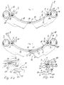
- Fig.3
- in vergrößertem Maßstab die Ausbildung der Fugen zwischen den Schmalseiten einer Öffnungsklappe und dem als Behälter dienenden Mischergehäuse einerseits im Bereich von Schwenkachsen und andererseits in dem Bereich, in dem zwei Öffnungsklappen zusammenstoßen,
- Fig.4
- eine der Fig.3 entsprechende Darstellung, bei welcher die in dieser Figur rechte Öffnungsklappe teilweise geöffnet ist,
- Fig.4a
- in noch weiter vergrößerter Darstellung eine Ansicht in Richtung einer ersten, parallel zu der Schwenkachse verlaufenden Schmalseite der Öffnungsklappe, die schräg angeordnet ist und die Gegenschräge der Entleeröffnung sowie den von der ersten Schmalseite beim Öffnen oder Schließen beschriebenen Kreis, an welchen diese erste Schmalseite und die Gegenschräge der Entleeröffnung angepaßt sind,
- Fig.4b
- im Maßstab der Fig.4a eine zweite Schmalseite der in Fig.4 rechts befindlichen Öffnungsklappe und ihren Öffnungs- oder Schließweg bzw. den diesem etwa entsprechenden Kreis sowie die zweite Schmalseite der zweiten Öffnungsklappe, die aber auch die Gegenschräge einer bis dort verlaufenden Entleeröffnung sein könnte,
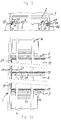
- Fig.5
- einen Längsschnitt des Behälters mit seiner Entleeröffnung,
- Fig.5a
- eine Ansicht der in Schließstellung befindlichen Öffnungsklappen von unten und jeweils eine ihrer ihre Schwenkachse bildenden Schwenklagerungen,
- Fig.6
- eine der Fig.3 entsprechende Darstellung, wobei der Behälter nur eine um eine Schwenkachse verschwenkbare Öffnungsklappe aufweist sowie
- Fig.7
- eine der Fig.6 entsprechende Darstellung, bei welcher die einzige Öffnungsklappe aus ihrer Schließstellung teilweise herausgeschwenkt ist, um bei einer weiteren Verschwenkung ihre etwa vertikale Öffnungsposition zu erreichen.
Claims (11)
- Schüttgutbehälter, insbesondere Behälter (1) für Baustoffe oder Baustoffmischungen, mit wenigstens einer um eine Schwenkachse (3) schwenkbaren, insbesondere rechteckigen Öffnungsklappe (2) zum Verschließen einer Entleeröffnung des Behälters (1), wobei zumindest die der Schwenkachse (3) nahe oder parallele erste Schmalseite (5) dieser Öffnungsklappe (2) über wenigstens einen Teil ihres Querschnittes schräg ausgebildet ist und zwischen sich und der Oberfläche der Öffnungsklappe (2) einen von 90° abweichenden Winkel einschließt, wobei die Behälter- oder Entleeröffnung eine derart dazu passende Gegenschräge (6) hat, daß die erste Schmalseite (5) der Öffnungsklappe (2) und die Gegenschräge (6) der Entleeröffnung in Gebrauchsstellung zumindest bereichsweise etwa parallel zueinander verlaufen, wobei die im Querschnitt schräg angeordnete erste Schmalseite (5) der Öffnungsklappe (2) mit der Oberfläche der Außenseite (8) dieser Öffnungsklappe (2) einen stumpfen Winkel einschließt, und wobei der Verlauf dieser Schmalseite (5) an den von ihr beim Öffnen und Schließen beschriebenen Kreis (9) um die Schwenkachse (3) der Öffnungsklappe zumindest angenähert ist, dadurch gekennzeichnet, daß der Querschnitt der Gegenschräge (6) der Entleeröffnung dazu passend mit der Außenseite (10) des Behälters (1) einen spitzen Winkel einschließt, daß die Öffnunsklappe (2) gegenüber der Entleeröffnung mittels wenigstens einer Dichtung (19) abgedichtet ist und daß die Dichtung (19) als Dichtleiste der Fuge zwischen geschlossener Öffnungsklappe (2, 18) und Gegenschräge (6, 17) benachbart an der Außenseite angeordnet ist und ihre wirksame Dichtfläche (20) im Querschnitt gesehen im Bereich des Schwenkkreises (9, 16) oder Schwenkzylinders verläuft, den die Schmalseite (5, 15) der Öffnungsklappe (2) und/oder eine dazu benachbarte Anschlagleiste (21) beschreibt, wobei die Dichtfläche (20) und/oder die Gegenfläche (22) diesen Schwenkkreis (9, 16) oder Schwenkzylinder berührt oder unter spitzem Winkel schneidet.
- Schüttgutbehälter nach Anspruch 1, dadurch gekennzeichnet, daß die schräge erste Schmalseite (5) der Öffnungsklappe (2), im Querschnitt gesehen, mit deren Innenseite (11) einen spitzen Winkel einschließt, dessen Kante (12) beim Verschwenken in Schließstellung als Abstreifer zumindest an der Gegenschräge (6) dient.
- Schüttgutbehälter nach einem der Ansprüche 1 bis 2, dadurch gekennzeichnet, daß auch die parallel zu der der Schwenkachse (3) nahen ersten Schmalseite (5) verlaufende zweite Schmalseite (15) der Öffnungsklappe (2) eine etwa schräg zur Außenseite (8) der Klappe (2) verlaufende, insbesondere an den Kreis (16) angenäherte Querschnittsform hat, der von ihr beim Verschwenken um die Schwenkachse (3) beschrieben wird, und daß die von der zweiten Schmalseite (15) in Schließstellung beaufschlagte Gegenschräge (17) an der Entleeröffnung oder an einer weiteren Öffnungsklappe (18) eine dazu passende, etwa parallel verlaufende Querschnittsform hat.
- Schüttgutbehälter nach einem der Ansprüche 1 bis 3, dadurch gekennzeichnet, daß die zweite Schmalseite (15) mit der Außenseite (8) der Öffnungsklappe (2) einen stumpfen und mit der Innenseite (11) der Öffnungsklappe (2) einen spitzen Winkel einschließt und die zwischen der Schmalseite (15) und der Innenseite (11) befindlichen Kante (12) als Abstreifer dient.
- Schüttgutbehälter nach einem der Ansprüche 1 bis 4, dadurch gekennzeichnet, daß der Querschnitt der ersten und/oder der zweiten Schmalseite (5, 15) etwa einer Tangente an den jeweiligen Schwenkkreis (9, 16) oder Schwenkzylinder dieser Schmalseiten um die Schwenkachse (3) der Öffnungsklappe (2) entspricht und die Schmalseite(n) im wesentlichen eben ausgebildet ist(sind).
- Schüttgutbehälter nach einem der vorstehenden Ansprüche, dadurch gekennzeichnet, daß die Öffnungsklappe eine große Wandstärke und/oder eine große Dicke hat, und daß die Schmalseite(n) einen polygonalen Querschnitt, also Bereiche mit unterschiedlichen Schrägungswinkel haben, wobei diese Bereiche jeweils Tangenten an den Hüllkreis oder den Hüllzylinder entsprechen, der beim Verschwenken der Öffnungsklappe von der/den Schmalseiten beschrieben wird.
- Schüttgutbehälter nach einem der Ansprüche 1 bis 6, dadurch gekennzeichnet, daß die Schmalseite(n) und/oder die Gegenschräge(n) für eine polygonale Formgebung ihres Querschnittes wenigstens zwei im Winkel zueinander stehende ebene Bereiche aufweisen, wobei der Winkel zwischen ihnen stumpf ist.
- Schüttgutbehälter nach Anspruch 1, dadurch gekennzeichnet, daß die Dichtung an der Außenseite des Behälters und ihre Dichtfläche (20) etwa in Fortsetzung der Gegenschräge der Entleeröffnung angeordnet ist und die Öffnungsklappe (2, 18) in Fortsetzung ihrer Schmalseite (5, 15) außenseitig eine etwa parallel zu der Schmalseite verlaufende, mit ihr im Querschnitt einen stumpfen Winkel bildende Anschlagleiste (21) zum Zusammenwirken mit dieser Dichtung (19) aufweist, deren der Dichtung zugewandte Druckfläche (22) im Querschnitt gesehen in Gebrauchsstellung insbesondere etwas schräg zu der Dichtfläche (20) der Dichtung verläuft und die Dichtung in dieser Gebrauchsstellung etwas verdrängt.
- Schüttgutbehälter nach Anspruch 1 oder 8, dadurch gekennzeichnet, daß die Dichtung (19) als Dichtleiste ausgebildet ist, deren Dichtfläche (20) bei entspannter, nicht beaufschlagter Dichtung im wesentlichen eben verläuft, und daß diese Dichtleiste vorzugsweise von der Dichtfläche (20) und einem dieser benachbarten Verdrängungsbereich (24) abgesehen ganz oder teilweise von einem Stützgehäuse (25) umschlossen ist.
- Schüttgutbehälter nach Anspruch 9, dadurch gekennzeichnet, daß das Stützgehäuse (25) für die Dichtung (19) zusammen mit dieser quer zur Längserstreckung der Dichtung (19) verstellbar und justierbar, insbesondere in Richtung zu der Öffnungsklappe (2, 18) hin verstellbar ist.
- Schüttgutbehälter nach einem der Ansprüche 1 bis 10, dadurch gekennzeichnet, daß die quer oder rechtwinklig zu der Schwenkachse (2) der Öffnungsklappe (2, 18) verlaufenden Schmalseiten (27) der Öffnungsklappe im Querschnitt gesehen mit deren Außen- und Innenseiten einen rechten Winkel bilden und die Ränder der Entleeröffnung dazu passend geformt sind und daß im Bereich dieser etwa rechtwinklig angeordneten Schmalseiten (27) vorzugsweise außenseitig an dem Rand der Entleeröffnung oder der Öffnungsklappe Dichtungen (19) vorgesehen sind, die mit relativ zu ihnen geneigten Gegenflächen (22) in dem Sinne zusammenwirken, daß sie beim Schließen der Öffnungsklappe (2, 18) durch diese relative Schrägung zunehmend zusammendrückbar sind.
Applications Claiming Priority (2)
| Application Number | Priority Date | Filing Date | Title |
|---|---|---|---|
| DE29804378U DE29804378U1 (de) | 1998-03-12 | 1998-03-12 | Schüttgutbehälter mit einer um eine Achse schwenkbaren Öffnungsklappe |
| DE29804378U | 1998-03-12 |
Publications (2)
| Publication Number | Publication Date |
|---|---|
| EP0941947A1 EP0941947A1 (de) | 1999-09-15 |
| EP0941947B1 true EP0941947B1 (de) | 2002-06-12 |
Family
ID=8054001
Family Applications (1)
| Application Number | Title | Priority Date | Filing Date |
|---|---|---|---|
| EP99104227A Expired - Lifetime EP0941947B1 (de) | 1998-03-12 | 1999-03-03 | Schüttgutbehälter mit einer um eine Achse schwenkbaren Öffnungsklappe |
Country Status (2)
| Country | Link |
|---|---|
| EP (1) | EP0941947B1 (de) |
| DE (2) | DE29804378U1 (de) |
Cited By (2)
| Publication number | Priority date | Publication date | Assignee | Title |
|---|---|---|---|---|
| US8225458B1 (en) | 2001-07-13 | 2012-07-24 | Hoffberg Steven M | Intelligent door restraint |
| USD684811S1 (en) | 2011-02-18 | 2013-06-25 | Buhler Ag | Batch mixer |
Family Cites Families (4)
| Publication number | Priority date | Publication date | Assignee | Title |
|---|---|---|---|---|
| DE344691C (de) * | ||||
| DE2903951C3 (de) * | 1979-02-02 | 1985-01-03 | Eirich, Hubert | Vorrichtung zum Verschließen einer Entleerungsöffnung in einem Behälterboden |
| DE3337437A1 (de) | 1983-10-14 | 1985-05-02 | Mathis System-Technik GmbH, 7844 Neuenburg | Chargenmischer |
| CH689667A5 (de) * | 1994-04-29 | 1999-08-13 | Buehler Ag | Chargenmischer. |
-
1998
- 1998-03-12 DE DE29804378U patent/DE29804378U1/de not_active Expired - Lifetime
-
1999
- 1999-03-03 EP EP99104227A patent/EP0941947B1/de not_active Expired - Lifetime
- 1999-03-03 DE DE59901692T patent/DE59901692D1/de not_active Expired - Lifetime
Cited By (4)
| Publication number | Priority date | Publication date | Assignee | Title |
|---|---|---|---|---|
| US8225458B1 (en) | 2001-07-13 | 2012-07-24 | Hoffberg Steven M | Intelligent door restraint |
| US9045927B1 (en) | 2001-07-13 | 2015-06-02 | Steven M. Hoffberg | Intelligent door restraint |
| US9121217B1 (en) | 2001-07-13 | 2015-09-01 | Steven M. Hoffberg | Intelligent door restraint |
| USD684811S1 (en) | 2011-02-18 | 2013-06-25 | Buhler Ag | Batch mixer |
Also Published As
| Publication number | Publication date |
|---|---|
| EP0941947A1 (de) | 1999-09-15 |
| DE59901692D1 (de) | 2002-07-18 |
| DE29804378U1 (de) | 1998-06-04 |
Similar Documents
| Publication | Publication Date | Title |
|---|---|---|
| EP0142003B1 (de) | Chargenmischer | |
| EP0255916B1 (de) | Auf eine Blechkante einer Fahrzeugkarosserie aufzusetzendes Dichtungsprofil | |
| DE3921339A1 (de) | Verpackung aus einem einteiligen zuschnitt aus karton | |
| EP0118883A2 (de) | Duschabtrennung in Form einer Klapptür | |
| CH676376A5 (en) | Strip-type door-leaf seal | |
| DE19714465C1 (de) | Elastische Strangdichtung für Fenster, Türen oder dgl. | |
| EP0941947B1 (de) | Schüttgutbehälter mit einer um eine Achse schwenkbaren Öffnungsklappe | |
| CH691616A5 (de) | Kunststoff-Fenster und Verfahren zu dessen Herstellung. | |
| WO2004029395A2 (de) | Fingerklemmschutz für ein aus gelenkig miteinander verbundenen sektionen bestehendes torblatt eines sektional- oder falltores | |
| EP0003132B1 (de) | Dosenverschlusskappe | |
| DE3922995C2 (de) | ||
| DE19809255A1 (de) | Kartusche zur Aufnahme einer viskosen oder pastösen Masse | |
| DE4240971C1 (de) | Beschickungskammer | |
| EP0416152A1 (de) | Fingerschutzprofil für Sektionaltore | |
| AT390123B (de) | Profil-strangdichtung aus elastischem material fuer fenster, tueren oder dgl. | |
| EP1780369A1 (de) | Elastisches Strangdichtungsprofil für Fenster, Türen oder dgl. | |
| EP3342973B1 (de) | Schwenk- und/oder schiebetüranlage | |
| DE102007006339B4 (de) | Tür für einen Aktenvernichter | |
| DE102018104922B3 (de) | Schaltprofil und Verfahren zu dessen Herstellung | |
| AT390300B (de) | Elastisches dichtungsprofil fuer fenster oder dgl. raumabschlussorgane | |
| DE60205154T2 (de) | Kopf zum Verdichten von Abfallstoffen | |
| DE69932149T2 (de) | Eine Tür, ein Türblatt und ein Türschliessverfahren | |
| DE2403078C2 (de) | Behälter für Massengüter | |
| DE8403073U1 (de) | Schwing- und drehfluegelfenster | |
| DE202005019332U1 (de) | Dichtungsprofil |
Legal Events
| Date | Code | Title | Description |
|---|---|---|---|
| PUAI | Public reference made under article 153(3) epc to a published international application that has entered the european phase |
Free format text: ORIGINAL CODE: 0009012 |
|
| AK | Designated contracting states |
Kind code of ref document: A1 Designated state(s): DE FR IT |
|
| AX | Request for extension of the european patent |
Free format text: AL;LT;LV;MK;RO;SI |
|
| 17P | Request for examination filed |
Effective date: 19990821 |
|
| AKX | Designation fees paid |
Free format text: DE FR IT |
|
| RIN1 | Information on inventor provided before grant (corrected) |
Inventor name: ELSAESSER, BERND Inventor name: KNOEPFLE XAVER Inventor name: DILGER UDO |
|
| 17Q | First examination report despatched |
Effective date: 20010313 |
|
| GRAG | Despatch of communication of intention to grant |
Free format text: ORIGINAL CODE: EPIDOS AGRA |
|
| GRAG | Despatch of communication of intention to grant |
Free format text: ORIGINAL CODE: EPIDOS AGRA |
|
| GRAH | Despatch of communication of intention to grant a patent |
Free format text: ORIGINAL CODE: EPIDOS IGRA |
|
| GRAH | Despatch of communication of intention to grant a patent |
Free format text: ORIGINAL CODE: EPIDOS IGRA |
|
| GRAA | (expected) grant |
Free format text: ORIGINAL CODE: 0009210 |
|
| AK | Designated contracting states |
Kind code of ref document: B1 Designated state(s): DE FR IT |
|
| REF | Corresponds to: |
Ref document number: 59901692 Country of ref document: DE Date of ref document: 20020718 |
|
| ET | Fr: translation filed | ||
| PLBE | No opposition filed within time limit |
Free format text: ORIGINAL CODE: 0009261 |
|
| STAA | Information on the status of an ep patent application or granted ep patent |
Free format text: STATUS: NO OPPOSITION FILED WITHIN TIME LIMIT |
|
| 26N | No opposition filed |
Effective date: 20030313 |
|
| REG | Reference to a national code |
Ref country code: FR Ref legal event code: PLFP Year of fee payment: 18 |
|
| REG | Reference to a national code |
Ref country code: FR Ref legal event code: PLFP Year of fee payment: 19 |
|
| PGFP | Annual fee paid to national office [announced via postgrant information from national office to epo] |
Ref country code: FR Payment date: 20170119 Year of fee payment: 19 |
|
| PGFP | Annual fee paid to national office [announced via postgrant information from national office to epo] |
Ref country code: IT Payment date: 20170328 Year of fee payment: 19 |
|
| PGFP | Annual fee paid to national office [announced via postgrant information from national office to epo] |
Ref country code: DE Payment date: 20170411 Year of fee payment: 19 |
|
| REG | Reference to a national code |
Ref country code: DE Ref legal event code: R119 Ref document number: 59901692 Country of ref document: DE |
|
| PG25 | Lapsed in a contracting state [announced via postgrant information from national office to epo] |
Ref country code: DE Free format text: LAPSE BECAUSE OF NON-PAYMENT OF DUE FEES Effective date: 20181002 |
|
| PG25 | Lapsed in a contracting state [announced via postgrant information from national office to epo] |
Ref country code: IT Free format text: LAPSE BECAUSE OF NON-PAYMENT OF DUE FEES Effective date: 20180303 |
|
| PG25 | Lapsed in a contracting state [announced via postgrant information from national office to epo] |
Ref country code: FR Free format text: LAPSE BECAUSE OF NON-PAYMENT OF DUE FEES Effective date: 20180331 |