EP0941853B1 - Tintenschreibervorrichtung - Google Patents
Tintenschreibervorrichtung Download PDFInfo
- Publication number
- EP0941853B1 EP0941853B1 EP99301935A EP99301935A EP0941853B1 EP 0941853 B1 EP0941853 B1 EP 0941853B1 EP 99301935 A EP99301935 A EP 99301935A EP 99301935 A EP99301935 A EP 99301935A EP 0941853 B1 EP0941853 B1 EP 0941853B1
- Authority
- EP
- European Patent Office
- Prior art keywords
- ink
- pen
- cartridge
- nest
- pen cartridge
- Prior art date
- Legal status (The legal status is an assumption and is not a legal conclusion. Google has not performed a legal analysis and makes no representation as to the accuracy of the status listed.)
- Expired - Lifetime
Links
- 239000000758 substrate Substances 0.000 claims description 16
- 230000004888 barrier function Effects 0.000 claims description 11
- 239000003595 mist Substances 0.000 claims description 8
- 238000004891 communication Methods 0.000 claims description 7
- 239000012530 fluid Substances 0.000 claims description 5
- 230000000903 blocking effect Effects 0.000 claims description 4
- 239000007921 spray Substances 0.000 claims description 3
- 229910001220 stainless steel Inorganic materials 0.000 claims description 3
- 239000010935 stainless steel Substances 0.000 claims description 3
- 239000003086 colorant Substances 0.000 description 3
- 230000037452 priming Effects 0.000 description 3
- MCMNRKCIXSYSNV-UHFFFAOYSA-N Zirconium dioxide Chemical compound O=[Zr]=O MCMNRKCIXSYSNV-UHFFFAOYSA-N 0.000 description 2
- 239000004593 Epoxy Substances 0.000 description 1
- 239000000919 ceramic Substances 0.000 description 1
- 238000004140 cleaning Methods 0.000 description 1
- 239000011248 coating agent Substances 0.000 description 1
- 238000000576 coating method Methods 0.000 description 1
- 230000001419 dependent effect Effects 0.000 description 1
- 238000005530 etching Methods 0.000 description 1
- 230000001939 inductive effect Effects 0.000 description 1
- 238000003780 insertion Methods 0.000 description 1
- 230000037431 insertion Effects 0.000 description 1
- 239000000155 melt Substances 0.000 description 1
- 238000000034 method Methods 0.000 description 1
- 238000005192 partition Methods 0.000 description 1
- 229920002120 photoresistant polymer Polymers 0.000 description 1
- 238000004382 potting Methods 0.000 description 1
- 239000007787 solid Substances 0.000 description 1
- 230000000638 stimulation Effects 0.000 description 1
- 238000012384 transportation and delivery Methods 0.000 description 1
Images




Classifications
-
- B—PERFORMING OPERATIONS; TRANSPORTING
- B41—PRINTING; LINING MACHINES; TYPEWRITERS; STAMPS
- B41J—TYPEWRITERS; SELECTIVE PRINTING MECHANISMS, i.e. MECHANISMS PRINTING OTHERWISE THAN FROM A FORME; CORRECTION OF TYPOGRAPHICAL ERRORS
- B41J2/00—Typewriters or selective printing mechanisms characterised by the printing or marking process for which they are designed
- B41J2/005—Typewriters or selective printing mechanisms characterised by the printing or marking process for which they are designed characterised by bringing liquid or particles selectively into contact with a printing material
- B41J2/01—Ink jet
- B41J2/015—Ink jet characterised by the jet generation process
- B41J2/02—Ink jet characterised by the jet generation process generating a continuous ink jet
- B41J2/025—Ink jet characterised by the jet generation process generating a continuous ink jet by vibration
-
- B—PERFORMING OPERATIONS; TRANSPORTING
- B41—PRINTING; LINING MACHINES; TYPEWRITERS; STAMPS
- B41J—TYPEWRITERS; SELECTIVE PRINTING MECHANISMS, i.e. MECHANISMS PRINTING OTHERWISE THAN FROM A FORME; CORRECTION OF TYPOGRAPHICAL ERRORS
- B41J2/00—Typewriters or selective printing mechanisms characterised by the printing or marking process for which they are designed
- B41J2/005—Typewriters or selective printing mechanisms characterised by the printing or marking process for which they are designed characterised by bringing liquid or particles selectively into contact with a printing material
- B41J2/01—Ink jet
- B41J2/07—Ink jet characterised by jet control
- B41J2/075—Ink jet characterised by jet control for many-valued deflection
- B41J2/08—Ink jet characterised by jet control for many-valued deflection charge-control type
-
- B—PERFORMING OPERATIONS; TRANSPORTING
- B41—PRINTING; LINING MACHINES; TYPEWRITERS; STAMPS
- B41J—TYPEWRITERS; SELECTIVE PRINTING MECHANISMS, i.e. MECHANISMS PRINTING OTHERWISE THAN FROM A FORME; CORRECTION OF TYPOGRAPHICAL ERRORS
- B41J2/00—Typewriters or selective printing mechanisms characterised by the printing or marking process for which they are designed
- B41J2/005—Typewriters or selective printing mechanisms characterised by the printing or marking process for which they are designed characterised by bringing liquid or particles selectively into contact with a printing material
- B41J2/01—Ink jet
- B41J2/17—Ink jet characterised by ink handling
- B41J2/175—Ink supply systems ; Circuit parts therefor
-
- B—PERFORMING OPERATIONS; TRANSPORTING
- B41—PRINTING; LINING MACHINES; TYPEWRITERS; STAMPS
- B41J—TYPEWRITERS; SELECTIVE PRINTING MECHANISMS, i.e. MECHANISMS PRINTING OTHERWISE THAN FROM A FORME; CORRECTION OF TYPOGRAPHICAL ERRORS
- B41J2/00—Typewriters or selective printing mechanisms characterised by the printing or marking process for which they are designed
- B41J2/005—Typewriters or selective printing mechanisms characterised by the printing or marking process for which they are designed characterised by bringing liquid or particles selectively into contact with a printing material
- B41J2/01—Ink jet
- B41J2/17—Ink jet characterised by ink handling
- B41J2/175—Ink supply systems ; Circuit parts therefor
- B41J2/17503—Ink cartridges
- B41J2/1752—Mounting within the printer
-
- B—PERFORMING OPERATIONS; TRANSPORTING
- B41—PRINTING; LINING MACHINES; TYPEWRITERS; STAMPS
- B41J—TYPEWRITERS; SELECTIVE PRINTING MECHANISMS, i.e. MECHANISMS PRINTING OTHERWISE THAN FROM A FORME; CORRECTION OF TYPOGRAPHICAL ERRORS
- B41J2/00—Typewriters or selective printing mechanisms characterised by the printing or marking process for which they are designed
- B41J2/005—Typewriters or selective printing mechanisms characterised by the printing or marking process for which they are designed characterised by bringing liquid or particles selectively into contact with a printing material
- B41J2/01—Ink jet
- B41J2/17—Ink jet characterised by ink handling
- B41J2/18—Ink recirculation systems
- B41J2/185—Ink-collectors; Ink-catchers
-
- B—PERFORMING OPERATIONS; TRANSPORTING
- B41—PRINTING; LINING MACHINES; TYPEWRITERS; STAMPS
- B41J—TYPEWRITERS; SELECTIVE PRINTING MECHANISMS, i.e. MECHANISMS PRINTING OTHERWISE THAN FROM A FORME; CORRECTION OF TYPOGRAPHICAL ERRORS
- B41J2/00—Typewriters or selective printing mechanisms characterised by the printing or marking process for which they are designed
- B41J2/005—Typewriters or selective printing mechanisms characterised by the printing or marking process for which they are designed characterised by bringing liquid or particles selectively into contact with a printing material
- B41J2/01—Ink jet
- B41J2/17—Ink jet characterised by ink handling
- B41J2/18—Ink recirculation systems
- B41J2/185—Ink-collectors; Ink-catchers
- B41J2002/1853—Ink-collectors; Ink-catchers ink collectors for continuous Inkjet printers, e.g. gutters, mist suction means
Definitions
- the invention relates to an ink pen assembly of a continuous ink jet printer.
- continuous ink jet printers produce a continuous stream of ink drops directed at a substrate.
- the ink drops include printing and non-printing drops.
- the ink drops are selectively charged such that the non-printing drops are deflected to prevent the non-printing drops from reaching the substrate.
- a removable nozzle unit including a charging tunnel for producing a continuous stream of ink drops and charging the non-printing drops is described in Fargo et al., U.S Patent No. 5,160,938, titled METHOD AND MEANS FOR CALIBRATING AN INK JET PRINTER.
- a modular printhead system forming the preamble of claim 1 is disclosed in US-A-4809015.
- a catcher for inkjet droplets is disclosed in US-A-3813675.
- an ink pen cartridge as claimed in claim 1 herein.
- an ink pen assembly as claimed in claim 15 herein.
- an ink pen assembly 10 of a continuous ink jet printer includes a printhead nest 16 and up to four disposable ink pen cartridges 14, one cartridge being shown in Fig. 1, received by nest 16.
- Nest 16 is a component of a pen electronics board assembly 20 mounted to move along a lead screw 22 (Figs. 6B and 7) of the printer.
- Each ink pen preferably deliveries a different color ink to a substrate to produce a multi-color image on the substrate, as described, e.g., in Ingraham et al., U.S. Patent No. 5,416,612.
- the ink pen can be removed from the nest and replaced with a new ink pen.
- ink pen cartridge 14 includes a pen body 30 and a nozzle body 40.
- Nozzle body 40 is mounted to pen body 30 with pins 62, 64 which pass through mounting holes 32, 34 in pen body 30 and corresponding mounting holes 42, 44 in nozzle body 40.
- An ink block actuator e.g., knife edge arm 50, is mounted to pen body 30 to pivot about a pivot pin 66 received in mounting holes 36 of pen body 30.
- a finger grip 54 of arm 50 provides an easy means for the user to grasp ink pen 14 for insertion and removal from nest 16.
- a charge tunnel 72 housed within an electrode mounting section 70 of pen body 30 is a charge tunnel 72, a ground deflection electrode 74, a high voltage deflection electrode 76, and an ink blocking element, e.g., knife edge 94.
- a barrier plate 71 defines a drop charging chamber 93 in which the charge tunnel, electrodes, and knife edge are located. Extending from either side of barrier plate 71 are a knife edge mount 84, a charge tunnel mount 73, a ground electrode mount 75, and a deflection electrode mount 77.
- Each of the mounts 84, 73, 75, 77 defines a through bore 83, 73a, 75a, 77a, respectively.
- a knife edge housing 80 includes a shaft 82 which extends through bore 83 of knife edge mount 84. Bore 83 has a slot 85 which permits flow of air into charging chamber 93.
- end 86 of shaft 82 is received within arm 50 such that a hole 88 in shaft 82 is aligned with a pair of holes 56 (only one hole is shown in Fig. 3A) in arm 50.
- holes 56 and 88 are aligned with a pair of slots 38 in pen body 30.
- a pin 68 passes through slots 38 and holes 56 and 88 such that movement of arm 50 about its pivot point causes pin 68 to slide vertically within slots 38 thus changing the vertical position of knife edge 94.
- a spring 90 captured between guide 84 and arm 50 biases arm 50 to pivot about pivot pin 66 in the direction of arrow 90a.
- Shafts 72a, 74a, 76a of the charge tunnel, ground electrode, and deflection electrode, respectively, are mounted within through bores 73a, 75a, 77a, respectively.
- the charge tunnel, electrodes and knife edge are spaced from barrier plate 71, e.g., by about 0.95 cm (3/8 inch), and barrier plate 71 is inclined, e.g., by about 45 degrees, with respect to a side wall 95 of drop charging chamber 93. This spacing tends to limit spray of ink onto barrier plate 71, and the inclined position of the barrier plate facilitates dripping of any ink that does reach the barrier plate off of the barrier plate.
- printing ink is received at a first end 46 of nozzle body 40 and is delivered as discrete ink droplets from a second end 48 of the nozzle body.
- Non-printing ink drops exiting from nozzle body 40 are charged when passing through a hole 92 in charge tunnel 72.
- the charged non-printing ink drops are deflected by electrodes 74, 76 in a direction transverse to a direction of travel of the substrate (see arrow A, Fig. 6B) such that the non-printing drops impact knife edge 94 preventing the non-printing ink drops from reaching the substrate.
- knife edge 94 has a curved ink contacting surface 94a along an edge 94b.
- the knife edge is preferably formed from, e.g., zirconia ceramic, that is injected molded and then ground on one side to produce a sharp edge. Non-printing ink drops hit surface 94a and roll down the knife edge.
- a bottom cap 100 (Figs. 3A and 4A) mounted to pen body 30 includes a drain port 102 through which non-printing ink drops falling from knife edge 94 pass to a collection tray 104 of nest 16 (Fig. 1).
- Bottom cap 100 also defines a drip-inducing post 103 positioned below ground electrode 74 to induce any ink which may fall on electrode 74 to drip off of electrode 74.
- a nest mounting guide 79 extends from a bottom surface 101 of cap 100.
- Printing ink drops passing through charge tunnel 72 are charged to a lesser degree than the non-printing ink drops such that the printing ink drops are not deflected by the electrodes into the knife edge.
- the printing ink drops pass by the knife edge and through an outlet 98 to contact the substrate.
- a mist bib 110 is positioned over lower section 111 of mounting section 70.
- Lower section 111 includes four protrusions 113 (two protrusions are shown in Fig. 3A) over which holes 115 in mist bib 110 are positioned to mount mist bib 110 to lower section 111.
- Mist bib 110 defines an outlet 98a through which the printing ink drops pass to contact the substrate.
- Mist bib 110 acts to collect spray formed when the ink drops contact the substrate.
- Mist bib 110 is formed, e.g., by photo-mask engraving stainless steel having a photoresist coating, and acid-etching the exposed areas of the stainless steel.
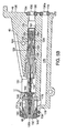
- the ink jet nozzle body 40 defines an ink passage 120 having an inlet 130 and an outlet 132.
- An o-ring cavity 134 located at inlet 130 in a face 135 of nozzle body 40 houses an o-ring 136.
- O-ring 136 provides a seal with nest 16, described further below.
- a jet housing 122 is received in passage 120 with an o-ring 123 providing a seal between jet housing 122 and a wall 121 of passage 120.
- Jet housing 122 includes a body 124 defining a channel 126.
- a capillary tube 128, e.g., a 100 micron inner diameter tube, located within channel 126 has an inlet end 128a and an outlet end 128b extending to outlet 132.
- Tube 128 has a 10 micron restriction at outlet end 128b.
- a piezoelectric transducer 140 is received over capillary tube 128. The restriction in tube 128 and transducer 140 cause ink flowing through tube 128 to be broken into discrete ink drops, as described in West et al., U.S. Patent No. 5,407,136, titled INK-JET NOZZLE. Transducer 140 acts to synchronize the breakup of the ink into drops. Ink flowing in inlet 130 passes through filter 129 before entering tube 128. Filter 129 is glued in place, e.g., by a preformed epoxy ring which melts at a given temperature.
- a pair of springs 142, 144 are positioned over tube 128 on either side of transducer 140.
- the springs locate transducer 140 with respect to tube 128 prior to fixing the transducer to the tube.
- Spring 142 is connected to a ground plane of the transducer to act as a shield.
- a nozzle 146 supports tube 128.
- An end cap 148 provides a seal around tube 128 at outlet end 132 of ink passage 120.
- An o-ring 150 provides a seal between pen body 30 and nozzle body 40.
- solid potting is applied through an opening 151 in nozzle body 40.
- Nozzle body 40 also defines a vacuum passage 170.
- a second o-ring cavity 172 located at a vacuum inlet 130a in end face 135 of the nozzle body houses an o-ring 174.
- O-ring 174 provides a seal with nest 16, described further below.
- An outlet 176 of vacuum passage 179 communicates with the distal end of the tube through region 178 surrounding nozzle 146 and channel 180 defined between end cap 148 and nozzle 146. Cleaning fluid can be pumped into chamber 93 through vacuum passage 170.
- An o-ring cover 188 (Fig. 2) is provided to retain o-rings 136, 174 in o-ring cavities 134, 172, respectively, prior to positioning of the ink pen in the printhead nest.
- O-ring cover 188 includes a t-slot 189 which fits over a nozzle body lip 121.
- ink pen 14 is also in electrical and mechanical connection with nest 16.
- an electrical connection board 202 mounted to an underside 200 of ink pen body 30 is an electrical connection board 202.
- Board 202 includes electrical contacts 204 which interface with nest 16 to provide signals to transducer 140, charge tunnel 72, and electrodes 74, 76, as described further below.
- the charge applied to the printing ink drops by the charge tunnel is varied to adjust the deflection of the printing ink drops in a direction transverse to the direction of travel of the substrate.
- electrodes 74, 76 are oriented with respect to the direction of travel of the substrate (along arrow A) such that the electrodes deflect the ink drops along arrow B, oriented in a direction transverse to substrate travel and in the direction of travel of ink pen assembly 10. This results in a trajectory of the ink drop along arrow C.
- the knife edge is moved by adjusting the position of the knife edge arm, as described below, to insure that non-printing drops hit the knife edge while the printing drops pass by the knife edge.
- Registration of four ink colors delivered by the four ink pens is performed by adjusting the charge applied to the printing ink drops by the charge tunnel (by varying the voltage applied to the charge tunnel), and by adjusting the pixel locations in the direction of substrate travel, as described in Ingraham et al., supra.
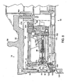
- nest 16 includes five partitions 220 defining four ink pen receiving t-slots 222. Lip 221 (Fig. 3A) of nozzle body 40 slides into t-slot 222 to connect nozzle body 40 to nest 16.
- Nest 16 also includes four pins 240. Guide 79 of ink pen cap 100 is received over a respective pin 240 to help align the ink pen with the nest.
- In a back wall 224 of each slot 222 is an ink outlet 230 and a vacuum outlet 232.
- ink outlet 230 is in fluid communication with ink passage 120 of nozzle body 40
- vacuum outlet 232 is in fluid communication with vacuum passage 170 of nozzle body 40.
- O-rings 136, 174 provide seals between wall 224 of nest 16 and end face 135 of nozzle body 40.
- nest 16 includes four electrical contact regions 250. with ink pen 14 positioned in nest 16, contacts 204 of board 202 interface with contact region 250.
- Each contact region 250 includes six contact points: a 2000 volt power supply; a charge tunnel charge level signal for adjusting the charge imparted to the ink drops by the charge tunnel; a 1 MHz stimulation voltage to the transducer; an ink pen ground; an ink pen sensor; and a primer fixture (described below) sensor.
- the ink pen sensor and primer fixture sensor sense when an ink pen or the primer fixture are in place in the nest.
- LEDs 252 (Fig. 1) signal when an ink pen or the primer fixture is in position in the nest.
- Nest 16 also includes motor actuated, knife edge positioning pins 260.
- Each pin 260 contacts an undersurface 210 of arm 50. Raising and lowering of pin 260 causes arm 50 to pivot about its pivot point, thus adjusting the vertical position of knife edge 94.
- An ink pen is inserted into nest 16 simply by grasping finger grip 54 and sliding lip 221 of nozzle body 14 into slot 222.
- the individual ink pen is removed from nest 16 simply by pulling up on finger grip 54.
- the ink pen is hot swapable, i.e., the power to the ink jet printer can be left on when an ink pen is removed from the nest and a new ink pen inserted into the nest.
- the ink pen sensing contact of the nest detects when the ink pen has been removed and shuts down dangerous voltages until the new ink pen is inserted.
- a priming pen 300 is provided.
- Pen 300 includes four slots 302 which are received within t-slots 222.
- Pen 300 includes four electrical contacts 304 which interface with contact region 250 to provide a signal indicating that the priming pen is in position in nest 16.
- the nest can be configured to accept more than four ink pens. Eight ink pens would permit color printing twice as fast as with four ink pens, would allow the use of high and low density colors to expand the color range, and would also permit additional colors to be used while printing.
Landscapes
- Ink Jet (AREA)
- Particle Formation And Scattering Control In Inkjet Printers (AREA)
- Pens And Brushes (AREA)
Claims (16)
- Tintenpatrone (14), die so angeordnet ist, dass sie entfernbar in einer Druckkopfaufnahme eines Tintenstrahlsdruckers mit kontinuierlicher Tintenzufuhr aufgenommen wird, wobei die Tintenpatrone folgendes umfasst:einen Patronenkörper (30), der so konfiguriert ist, dass er in elektrischer Übertragungsverbindung mit der Druckkopfaufnahme platziert werden kann;einen Düsenkörper (40), der mit dem Patronenkörper verbunden ist, wobei der Düsenkörper einen Einlass definiert, der so konfiguriert ist, dass er in Fluidübertragungsverbindung mit der Druckkopfaufnahme platziert werden kann, um davon Tinte zu empfangen, wobei der Düsenkörper ferner einen Auslass definiert, durch den Tinte ausgestoßen wird;eine Ablenkelektrode (76), die mit dem Patronenkörper verbunden ist, um geladene Tintentröpfchen abzulenken, die von der aus dem Düsenkörperauslass ausgestoßenen Tinte ausbrechen; gekennzeichnet durch:ein Tintenblockierungs-Betätigungselement (50), das mit dem Patronenkörper verbunden ist, wobei das Tinteblockierungs-Betätigungselement so konfiguriert ist, dass es in mechanischer Verbindung (66) mit der Druckkopfaufnahme platziert werden kann, wobei die Bewegung der Tintenblockierungs-Betätigungseinrichtung im Verhältnis zu dem Patronenkörper dazu dient, die Position eines Tintenblockierungselements anzupassen.
- Tintenpatrone nach Anspruch 1, wobei diese ferner eine Ladungselektrode (74) umfasst, die mit dem Patronenkörper verbunden ist, um Tintentröpfchen zu laden, die von der aus dem Düsenkörperauslass ausgestoßenen Tinte ausbrechen.
- Tintenpatrone nach Anspruch 1 oder 2, wobei diese ferner eine Tintenblockierungsfassung umfasst, die mit dem Patronenkörper und dem Tintenblockierungs-Betätigungselement verbunden ist, wobei die Tintenblockierungsfassung das Tintenblockierungselement (94) zum Ableiten der abgelenkten Tintentröpfchen aufweist.
- Tintenpatrone nach Anspruch 3, wobei das Tintenblockierungs-Betätigungselement an dem Patronenkörper angebracht wird, um sich im Verhältnis zu dem Patronenkörper zu drehen.
- Tintenpatrone nach Anspruch 1, wobei der Düsenkörper eine Röhre (120) aufweist, durch welche Tinte fließt, und wobei ein Messwandler (140) an der Röhre angebracht ist, um das Ausbrechen von aus dem Düsenkörperauslass ausgestoßener Tinte in Tintentröpfchen zu synchronisieren.
- Tintenpatrone nach Anspruch 1, wobei der Patronenkörper einen Tintenauslass für das Auslassen von Tinte aus dem Patronenkörper zu der Druckkopfaufnahme definiert.
- Tintenpatrone nach Anspruch 1, wobei diese ferner einen Sprühnebelfänger (110) umfasst, der an dem Patronenkörper angebracht ist, um den Sprühnebel zu sammeln, der erzeugt wird, wenn Tintentröpfchen ein Substrat berühren.
- Tintenpatrone nach Anspruch 7, wobei der Sprühnebelfänger aus säuregeätztem Edelstahl gebildet wird.
- Tintenpatrone nach Anspruch 1, wobei diese ferner eine elektrische Anschlussplatte (202) umfasst, die an dem Patronenkörper angebracht ist, um die elektrische Kommunikation mit der Druckkopfaufnahme bereitzustellen.
- Tintenpatrone nach Anspruch 1, wobei der Patronenkörper eine Grenzplatte (71) aufweist, die eine Tropfenladungskammer definiert, einen Ladungstunnel und die Ablenkelektroden, die in der Tropfenladungskammer und räumlich getrennt von der Grenzplatte angeordnet sind.
- Tintenpatrone nach Anspruch 10, wobei die Grenzplatte im Verhältnis zu einer Seitenwand der Tropfenladungskammer schräg steht.
- Druckkopfaufnahme (16), die so angeordnet ist, dass sie eine Tintenpatrone nach Anspruch 1 aufnimmt, wobei die genannte Aufnahme folgendes aufweist:ein Gehäuse, das einen Tintenauslass zur Bereitstellung der Tinte an die Tintenpatrone definiert;eine mechanische Verbindung (66) zur Schnittstellenverbindung mit der Tintenpatrone, um die Position des Tintenblockierungselements der Tintenpatrone anzupassen; undeine elektrische Verbindung zur Schnittstellenverbindung mit der Tintenpatrone, um die Ablenkelektrode (76) der Tintenpatrone zu steuern.
- Druckkopfaufnahme nach Anspruch 12, wobei diese ferner einen Fluidfänger (104) zur Aufnahme der Tinte umfasst, die aus der Tintenpatrone ausläuft.
- Druckkopfaufnahme nach Anspruch 12 oder 13, wobei diese ferner vier Tintenauslässe umfasst, die durch das Gehäuse definiert sind, wobei jeder Tintenauslass dazu dient, Tinte an eine von vier Tintenpatronen, vier mechanische Verbindungen bereitzustellen, wobei jede mechanische Verbindung dazu dient, eine Schnittstellenverbindung mit einer der vier Tintenpatronen und vier elektrischen Verbindungen herzustellen, wobei jede elektrische Verbindung dazu dient, eine Schnittstellenverbindung mit einer der vier Tintenpatronen herzustellen.
- Tintenpatroneneinheit, die folgendes umfasst:eine Tintenpatrone nach Anspruch 1 und eine Druckkopfaufnahme nach Anspruch 12.
- Tintenstrahldrucker mit kontinuierlicher Tintenzufuhr, der folgendes umfasst:eine Druckaufnahme nach Anspruch 14.
Applications Claiming Priority (2)
| Application Number | Priority Date | Filing Date | Title |
|---|---|---|---|
| US42031 | 1998-03-13 | ||
| US09/042,031 US6270204B1 (en) | 1998-03-13 | 1998-03-13 | Ink pen assembly |
Publications (3)
| Publication Number | Publication Date |
|---|---|
| EP0941853A2 EP0941853A2 (de) | 1999-09-15 |
| EP0941853A3 EP0941853A3 (de) | 2000-04-19 |
| EP0941853B1 true EP0941853B1 (de) | 2006-10-25 |
Family
ID=21919681
Family Applications (1)
| Application Number | Title | Priority Date | Filing Date |
|---|---|---|---|
| EP99301935A Expired - Lifetime EP0941853B1 (de) | 1998-03-13 | 1999-03-12 | Tintenschreibervorrichtung |
Country Status (3)
| Country | Link |
|---|---|
| US (1) | US6270204B1 (de) |
| EP (1) | EP0941853B1 (de) |
| DE (1) | DE69933723T2 (de) |
Families Citing this family (18)
| Publication number | Priority date | Publication date | Assignee | Title |
|---|---|---|---|---|
| US6007318A (en) | 1996-12-20 | 1999-12-28 | Z Corporation | Method and apparatus for prototyping a three-dimensional object |
| US7037382B2 (en) | 1996-12-20 | 2006-05-02 | Z Corporation | Three-dimensional printer |
| US7147314B2 (en) * | 2003-06-18 | 2006-12-12 | Lexmark International, Inc. | Single piece filtration for an ink jet print head |
| US20040257412A1 (en) * | 2003-06-18 | 2004-12-23 | Anderson James D. | Sealed fluidic interfaces for an ink source regulator for an inkjet printer |
| US6786580B1 (en) | 2003-06-18 | 2004-09-07 | Lexmark International, Inc. | Submersible ink source regulator for an inkjet printer |
| US6837577B1 (en) * | 2003-06-18 | 2005-01-04 | Lexmark International, Inc. | Ink source regulator for an inkjet printer |
| US6776478B1 (en) | 2003-06-18 | 2004-08-17 | Lexmark International, Inc. | Ink source regulator for an inkjet printer |
| US6817707B1 (en) | 2003-06-18 | 2004-11-16 | Lexmark International, Inc. | Pressure controlled ink jet printhead assembly |
| US6796644B1 (en) | 2003-06-18 | 2004-09-28 | Lexmark International, Inc. | Ink source regulator for an inkjet printer |
| ATE425287T1 (de) | 2003-09-22 | 2009-03-15 | Ten Cate Advanced Textiles Bv | Verfahren und vorrichtung zur digitalen verbesserung von textil |
| US20050280185A1 (en) * | 2004-04-02 | 2005-12-22 | Z Corporation | Methods and apparatus for 3D printing |
| US7824001B2 (en) * | 2004-09-21 | 2010-11-02 | Z Corporation | Apparatus and methods for servicing 3D printers |
| US7387359B2 (en) * | 2004-09-21 | 2008-06-17 | Z Corporation | Apparatus and methods for servicing 3D printers |
| US7325912B2 (en) * | 2004-10-06 | 2008-02-05 | Hewlett-Packard Development Company, L.P. | Breachable seal |
| US7971991B2 (en) | 2006-05-26 | 2011-07-05 | Z Corporation | Apparatus and methods for handling materials in a 3-D printer |
| EP2926200B1 (de) | 2012-11-29 | 2020-06-03 | HP Indigo B.V. | Inkjet-drucksystem und tintenstrahldruckverfahren |
| US11780259B2 (en) | 2019-06-07 | 2023-10-10 | Hewlett-Packard Development Company, L.P. | Carriage bases |
| WO2020246983A1 (en) | 2019-06-07 | 2020-12-10 | Hewlett-Packard Development Company, L.P. | Rotating manifolds |
Family Cites Families (60)
| Publication number | Priority date | Publication date | Assignee | Title |
|---|---|---|---|---|
| US3798656A (en) | 1972-07-28 | 1974-03-19 | Ibm | Ink return system for a multijet ink jet printer |
| US3813675A (en) | 1973-03-28 | 1974-05-28 | Mead Corp | Catching apparatus for a jet drop recorder |
| US4035811A (en) | 1976-07-12 | 1977-07-12 | The Mead Corporation | Ink jet recorder and catcher therefor |
| DE2808275C2 (de) | 1978-02-27 | 1983-03-10 | NCR Corp., 45479 Dayton, Ohio | Tintenstrahldruckkopf |
| JPS5637171A (en) | 1979-09-03 | 1981-04-10 | Ricoh Co Ltd | Multideflection electrode unit for ink jet printer |
| US4246589A (en) | 1979-09-17 | 1981-01-20 | International Business Machines Corporation | Inertial deflection field tilting for bi-directional printing in ink jet printers |
| US4268836A (en) | 1979-10-25 | 1981-05-19 | The Mead Corporation | Ink jet printer having improved catcher |
| JPS5784858A (en) | 1980-11-18 | 1982-05-27 | Ricoh Co Ltd | Ink mist recovery device |
| JPS5869057A (ja) | 1981-10-20 | 1983-04-25 | Ricoh Co Ltd | インクシエツトプリンタのキヤリツジ装置 |
| US4442440A (en) | 1982-04-05 | 1984-04-10 | Xerox Corporation | Ink jet gutter method and apparatus |
| SE448845B (sv) | 1983-10-24 | 1987-03-23 | Esselte Sanden Ab | Forfarande och anordning for laddning vid bleckstraleskrivare |
| US4614953A (en) | 1984-04-12 | 1986-09-30 | The Laitram Corporation | Solvent and multiple color ink mixing system in an ink jet |
| US4540990A (en) | 1984-10-22 | 1985-09-10 | Xerox Corporation | Ink jet printer with droplet throw distance correction |
| WO1986002959A1 (en) | 1984-11-12 | 1986-05-22 | Commonwealth Scientific And Industrial Research Or | Droplet stream alignment for jet printers |
| US4639736A (en) * | 1985-07-09 | 1987-01-27 | Iris Graphics, Inc. | Ink jet recorder |
| US4636808A (en) | 1985-09-09 | 1987-01-13 | Eastman Kodak Company | Continuous ink jet printer |
| US4620198A (en) | 1985-11-20 | 1986-10-28 | Xerox Corporation | Multicolor ink jet printhead |
| US4668959A (en) | 1985-12-10 | 1987-05-26 | Iris Graphics Inc. | Mist reduction for ink jet printers |
| US4638328A (en) | 1986-05-01 | 1987-01-20 | Xerox Corporation | Printhead for an ink jet printer |
| GB8617123D0 (en) | 1986-07-14 | 1986-08-20 | Ici Plc | Printers |
| US4734711A (en) | 1986-12-22 | 1988-03-29 | Eastman Kodak Company | Pressure regulation system for multi-head ink jet printing apparatus |
| US4897667A (en) | 1987-12-17 | 1990-01-30 | Minolta Camera Kabushiki Kaisha | Ink jet printer |
| US4879565A (en) | 1988-01-27 | 1989-11-07 | Minolta Camera Kabushiki Kaisha | Ink jet printer |
| US4809015A (en) * | 1988-03-14 | 1989-02-28 | Eastman Kodak Company | Continuous ink jet printer having modular print head assembly |
| US4811035A (en) | 1988-03-14 | 1989-03-07 | Eastman Kodak Company | Modular two-color fluid system for continuous ink jet printer |
| USRE34932E (en) | 1988-03-16 | 1995-05-09 | Elmjet Limited | Continuous ink jet printing device |
| US4928113A (en) | 1988-10-31 | 1990-05-22 | Eastman Kodak Company | Constructions and fabrication methods for drop charge/deflection in continuous ink jet printer |
| US4928115A (en) | 1988-10-31 | 1990-05-22 | Eastman Kodak Company | Continuous ink jet printer having remotely operable print head assembly |
| US4928114A (en) | 1988-10-31 | 1990-05-22 | Eastman Kodak Company | Air skiving system for ink jet printer start-up |
| GB8829620D0 (en) | 1988-12-20 | 1989-02-15 | Elmjet Ltd | Continuous ink jet printer |
| GB8829625D0 (en) | 1988-12-20 | 1989-02-15 | Elmjet Ltd | Continuous ink jet printing device |
| US4929966A (en) | 1989-01-03 | 1990-05-29 | Eastman Kodak Company | Continuous ink jet printer with a gravity drain, catcher return system |
| KR0165677B1 (ko) | 1989-01-20 | 1999-05-01 | 요하네스 야코부스 스모렌버그 | 잉크-제트 방식 인쇄기용 노즐 |
| GB8915819D0 (en) | 1989-07-11 | 1989-08-31 | Domino Printing Sciences Plc | Continuous ink jet printer |
| US4937589A (en) | 1989-08-23 | 1990-06-26 | Eastman Kodak Company | Continuous ink jet print heads |
| US4999644A (en) | 1989-12-18 | 1991-03-12 | Eastman Kodak Company | User selectable drop charge synchronization for traveling wave-stimulated, continuous ink jet printers |
| US4999647A (en) | 1989-12-28 | 1991-03-12 | Eastman Kodak Company | Synchronous stimulation for long array continuous ink jet printer |
| GB9001654D0 (en) | 1990-01-24 | 1990-03-21 | Domino Printing Sciences Plc | Printhead for continuous ink jet printer |
| GB9001606D0 (en) | 1990-01-24 | 1990-03-21 | Domino Printing Sciences Plc | Continuous ink jet printer |
| US5160938A (en) | 1990-08-06 | 1992-11-03 | Iris Graphics, Inc. | Method and means for calibrating an ink jet printer |
| JP2673837B2 (ja) | 1990-11-05 | 1997-11-05 | シルバー精工株式会社 | 連続噴射型インクジェット記録装置 |
| JP2608806B2 (ja) | 1990-11-29 | 1997-05-14 | シルバー精工株式会社 | インクジェットプリンタにおけるレジストレーション調整装置 |
| US5105205A (en) | 1991-07-01 | 1992-04-14 | Eastman Kodak Company | Continuous ink jet catcher device having improved flow control construction |
| FR2678549B1 (fr) | 1991-07-05 | 1993-09-17 | Imaje | Procede et dispositif d'impression haute-resolution dans une imprimante a jet d'encre continu. |
| US5227813A (en) | 1991-08-16 | 1993-07-13 | Compaq Computer Corporation | Sidewall actuator for a high density ink jet printhead |
| GB2259276B (en) | 1991-09-06 | 1995-09-27 | Linx Printing Tech | Ink jet printer |
| JP2891439B2 (ja) | 1992-03-02 | 1999-05-17 | シルバー精工株式会社 | 連続噴射型インクジェット記録装置および そのインクジェット飛翔軸自動調整方法 |
| US5477254A (en) | 1992-03-30 | 1995-12-19 | Scitex Digital Printing, Inc. | Apparatus for mounting and aligning components of an ink jet printhead |
| US5428375A (en) | 1992-05-29 | 1995-06-27 | Simon; Robert J. | Multiple print head ink jet printer |
| US5475409A (en) | 1992-05-29 | 1995-12-12 | Scitex Digital Printing, Inc. | Alignment structure for components of an ink jet print head |
| US5407136A (en) * | 1992-09-18 | 1995-04-18 | Iris Graphics, Inc. | Ink-jet nozzle |
| US5416612A (en) | 1992-11-06 | 1995-05-16 | Iris Graphics Inc. | Apparatus and method for producing color half-tone images |
| US5675367A (en) * | 1992-12-23 | 1997-10-07 | Hewlett-Packard Company | Inkjet print cartridge having handle which incorporates an ink fill port |
| EP0647526A3 (de) | 1993-10-08 | 1995-08-23 | Iris Graphics Inc | Ablenkelektrode. |
| WO1995011424A1 (en) | 1993-10-20 | 1995-04-27 | Lasermaster Corporation | Automatic ink refill system for disposable ink jet cartridges |
| US5682191A (en) * | 1994-01-24 | 1997-10-28 | Iris Graphics Inc. | Ink jet printing apparatus having modular components |
| US5625397A (en) | 1994-11-23 | 1997-04-29 | Iris Graphics, Inc. | Dot on dot ink jet printing using inks of differing densities |
| EP0721844A1 (de) | 1995-01-11 | 1996-07-17 | Iris Graphics, Inc. | Tintenstrahldüse |
| EP0741040B1 (de) | 1995-05-04 | 2000-01-19 | SCITEX DIGITAL PRINTING, Inc. | Tintennebelsammler mit porösem Boden |
| GB9525970D0 (en) | 1995-12-19 | 1996-02-21 | Domino Printing Sciences Plc | Continuous ink jet printer |
-
1998
- 1998-03-13 US US09/042,031 patent/US6270204B1/en not_active Expired - Lifetime
-
1999
- 1999-03-12 EP EP99301935A patent/EP0941853B1/de not_active Expired - Lifetime
- 1999-03-12 DE DE69933723T patent/DE69933723T2/de not_active Expired - Lifetime
Also Published As
| Publication number | Publication date |
|---|---|
| EP0941853A2 (de) | 1999-09-15 |
| US6270204B1 (en) | 2001-08-07 |
| DE69933723T2 (de) | 2007-10-04 |
| DE69933723D1 (de) | 2006-12-07 |
| EP0941853A3 (de) | 2000-04-19 |
Similar Documents
| Publication | Publication Date | Title |
|---|---|---|
| US6270204B1 (en) | Ink pen assembly | |
| EP1047560B1 (de) | VORRICHTUNG UND VERFAHREN ZUR MEHRSTRAHLERZEUGUNG VON FLüSSIGKEIT HOHER VISKOSITÄt | |
| US4628332A (en) | Ink printhead with holder mount | |
| EP2130678B1 (de) | Kopfchip, Flüssigkeitsstrahlkopf, Flüssigkeitsstrahlaufzeichnungsvorrichtung und Verfahren zur Herstellung des Kopfchips | |
| IL165538A (en) | Printhead with ink reservoir and breather hole | |
| US8366241B2 (en) | Printhead having capped fluid passages | |
| WO2015187983A2 (en) | Continuous ink jet print head with zero adjustment embedded charging electrode | |
| US6588952B1 (en) | Ink feed arrangement for a print engine | |
| CA1258001A (en) | Ink jet recorder | |
| US6623113B2 (en) | Inkjet recording head including electrode assembly for deflecting ink droplets | |
| ATE224302T1 (de) | Tintenstrahlkopf und druckgerät damit versehen | |
| CA2060047A1 (en) | Ink jet recording head | |
| JPH07241998A (ja) | インクジェットプリンタのインクカートリッジ | |
| AU2004203190B2 (en) | An ink supply arrangement for a print engine | |
| JPH106518A (ja) | インクジェット記録装置 | |
| EP0805036A3 (de) | Oberseitig gespeister Tröpfchengenerator | |
| JP4066625B2 (ja) | インクジェット式記録装置 | |
| JP2003072053A (ja) | インクジェット式記録装置 | |
| KR100718192B1 (ko) | 프린트엔진용 잉크공급 조립체 | |
| JPS60204330A (ja) | 液体噴射記録装置 | |
| JPH01267045A (ja) | 記録装置 |
Legal Events
| Date | Code | Title | Description |
|---|---|---|---|
| PUAI | Public reference made under article 153(3) epc to a published international application that has entered the european phase |
Free format text: ORIGINAL CODE: 0009012 |
|
| AK | Designated contracting states |
Kind code of ref document: A2 Designated state(s): BE DE FR GB |
|
| AX | Request for extension of the european patent |
Free format text: AL;LT;LV;MK;RO;SI |
|
| RIC1 | Information provided on ipc code assigned before grant |
Free format text: 7B 41J 2/08 A, 7B 41J 2/135 B, 7B 41J 2/185 B |
|
| PUAL | Search report despatched |
Free format text: ORIGINAL CODE: 0009013 |
|
| AK | Designated contracting states |
Kind code of ref document: A3 Designated state(s): AT BE CH CY DE DK ES FI FR GB GR IE IT LI LU MC NL PT SE |
|
| AX | Request for extension of the european patent |
Free format text: AL;LT;LV;MK;RO;SI |
|
| 17P | Request for examination filed |
Effective date: 20001002 |
|
| AKX | Designation fees paid |
Free format text: BE DE FR GB |
|
| 17Q | First examination report despatched |
Effective date: 20040907 |
|
| GRAP | Despatch of communication of intention to grant a patent |
Free format text: ORIGINAL CODE: EPIDOSNIGR1 |
|
| RAP1 | Party data changed (applicant data changed or rights of an application transferred) |
Owner name: KODAK GRAPHIC COMMUNICATIONS COMPANY |
|
| GRAS | Grant fee paid |
Free format text: ORIGINAL CODE: EPIDOSNIGR3 |
|
| GRAA | (expected) grant |
Free format text: ORIGINAL CODE: 0009210 |
|
| AK | Designated contracting states |
Kind code of ref document: B1 Designated state(s): BE DE FR GB |
|
| PG25 | Lapsed in a contracting state [announced via postgrant information from national office to epo] |
Ref country code: BE Free format text: LAPSE BECAUSE OF FAILURE TO SUBMIT A TRANSLATION OF THE DESCRIPTION OR TO PAY THE FEE WITHIN THE PRESCRIBED TIME-LIMIT Effective date: 20061025 |
|
| REG | Reference to a national code |
Ref country code: GB Ref legal event code: FG4D |
|
| REF | Corresponds to: |
Ref document number: 69933723 Country of ref document: DE Date of ref document: 20061207 Kind code of ref document: P |
|
| PGFP | Annual fee paid to national office [announced via postgrant information from national office to epo] |
Ref country code: GB Payment date: 20070323 Year of fee payment: 9 |
|
| EN | Fr: translation not filed | ||
| PLBE | No opposition filed within time limit |
Free format text: ORIGINAL CODE: 0009261 |
|
| STAA | Information on the status of an ep patent application or granted ep patent |
Free format text: STATUS: NO OPPOSITION FILED WITHIN TIME LIMIT |
|
| 26N | No opposition filed |
Effective date: 20070726 |
|
| PG25 | Lapsed in a contracting state [announced via postgrant information from national office to epo] |
Ref country code: FR Free format text: LAPSE BECAUSE OF FAILURE TO SUBMIT A TRANSLATION OF THE DESCRIPTION OR TO PAY THE FEE WITHIN THE PRESCRIBED TIME-LIMIT Effective date: 20070608 |
|
| GBPC | Gb: european patent ceased through non-payment of renewal fee |
Effective date: 20080312 |
|
| PG25 | Lapsed in a contracting state [announced via postgrant information from national office to epo] |
Ref country code: FR Free format text: LAPSE BECAUSE OF FAILURE TO SUBMIT A TRANSLATION OF THE DESCRIPTION OR TO PAY THE FEE WITHIN THE PRESCRIBED TIME-LIMIT Effective date: 20061025 |
|
| PG25 | Lapsed in a contracting state [announced via postgrant information from national office to epo] |
Ref country code: GB Free format text: LAPSE BECAUSE OF NON-PAYMENT OF DUE FEES Effective date: 20080312 |
|
| PGFP | Annual fee paid to national office [announced via postgrant information from national office to epo] |
Ref country code: DE Payment date: 20140331 Year of fee payment: 16 |
|
| REG | Reference to a national code |
Ref country code: DE Ref legal event code: R119 Ref document number: 69933723 Country of ref document: DE |
|
| PG25 | Lapsed in a contracting state [announced via postgrant information from national office to epo] |
Ref country code: DE Free format text: LAPSE BECAUSE OF NON-PAYMENT OF DUE FEES Effective date: 20151001 |