EP0940995A2 - Verfahren und Gerät für die Herausziehung von Farbkonturinformation aus Videohalbbildern - Google Patents
Verfahren und Gerät für die Herausziehung von Farbkonturinformation aus Videohalbbildern Download PDFInfo
- Publication number
- EP0940995A2 EP0940995A2 EP99104390A EP99104390A EP0940995A2 EP 0940995 A2 EP0940995 A2 EP 0940995A2 EP 99104390 A EP99104390 A EP 99104390A EP 99104390 A EP99104390 A EP 99104390A EP 0940995 A2 EP0940995 A2 EP 0940995A2
- Authority
- EP
- European Patent Office
- Prior art keywords
- chrominance
- shape information
- sub
- shape
- luminance
- Prior art date
- Legal status (The legal status is an assumption and is not a legal conclusion. Google has not performed a legal analysis and makes no representation as to the accuracy of the status listed.)
- Granted
Links
Images


Classifications
-
- H—ELECTRICITY
- H04—ELECTRIC COMMUNICATION TECHNIQUE
- H04N—PICTORIAL COMMUNICATION, e.g. TELEVISION
- H04N11/00—Colour television systems
- H04N11/04—Colour television systems using pulse code modulation
- H04N11/042—Codec means
-
- H—ELECTRICITY
- H04—ELECTRIC COMMUNICATION TECHNIQUE
- H04N—PICTORIAL COMMUNICATION, e.g. TELEVISION
- H04N7/00—Television systems
- H04N7/01—Conversion of standards, e.g. involving analogue television standards or digital television standards processed at pixel level
-
- H—ELECTRICITY
- H04—ELECTRIC COMMUNICATION TECHNIQUE
- H04N—PICTORIAL COMMUNICATION, e.g. TELEVISION
- H04N19/00—Methods or arrangements for coding, decoding, compressing or decompressing digital video signals
- H04N19/10—Methods or arrangements for coding, decoding, compressing or decompressing digital video signals using adaptive coding
- H04N19/134—Methods or arrangements for coding, decoding, compressing or decompressing digital video signals using adaptive coding characterised by the element, parameter or criterion affecting or controlling the adaptive coding
- H04N19/157—Assigned coding mode, i.e. the coding mode being predefined or preselected to be further used for selection of another element or parameter
- H04N19/16—Assigned coding mode, i.e. the coding mode being predefined or preselected to be further used for selection of another element or parameter for a given display mode, e.g. for interlaced or progressive display mode
-
- H—ELECTRICITY
- H04—ELECTRIC COMMUNICATION TECHNIQUE
- H04N—PICTORIAL COMMUNICATION, e.g. TELEVISION
- H04N19/00—Methods or arrangements for coding, decoding, compressing or decompressing digital video signals
- H04N19/10—Methods or arrangements for coding, decoding, compressing or decompressing digital video signals using adaptive coding
- H04N19/169—Methods or arrangements for coding, decoding, compressing or decompressing digital video signals using adaptive coding characterised by the coding unit, i.e. the structural portion or semantic portion of the video signal being the object or the subject of the adaptive coding
- H04N19/186—Methods or arrangements for coding, decoding, compressing or decompressing digital video signals using adaptive coding characterised by the coding unit, i.e. the structural portion or semantic portion of the video signal being the object or the subject of the adaptive coding the unit being a colour or a chrominance component
-
- H—ELECTRICITY
- H04—ELECTRIC COMMUNICATION TECHNIQUE
- H04N—PICTORIAL COMMUNICATION, e.g. TELEVISION
- H04N19/00—Methods or arrangements for coding, decoding, compressing or decompressing digital video signals
- H04N19/20—Methods or arrangements for coding, decoding, compressing or decompressing digital video signals using video object coding
- H04N19/21—Methods or arrangements for coding, decoding, compressing or decompressing digital video signals using video object coding with binary alpha-plane coding for video objects, e.g. context-based arithmetic encoding [CAE]
-
- H—ELECTRICITY
- H04—ELECTRIC COMMUNICATION TECHNIQUE
- H04N—PICTORIAL COMMUNICATION, e.g. TELEVISION
- H04N19/00—Methods or arrangements for coding, decoding, compressing or decompressing digital video signals
- H04N19/85—Methods or arrangements for coding, decoding, compressing or decompressing digital video signals using pre-processing or post-processing specially adapted for video compression
- H04N19/86—Methods or arrangements for coding, decoding, compressing or decompressing digital video signals using pre-processing or post-processing specially adapted for video compression involving reduction of coding artifacts, e.g. of blockiness
Definitions
- the present invention relates in general to the extraction of chrominance shape information for an interlaced scan type image, and more particularly to a method and apparatus for extracting the chrominance shape information for the interlaced scan type image, in which chrominance and luminance signals are matched with each other in consideration of a characteristic of the interlaced scan type image, thereby overcoming a color bleeding phenomenon to enhance a subjective picture quality.
- video signal coding methods may be classified into a frame-based coding method which encodes the entire rectangular frame or picture and an object-based coding method which encodes only an arbitrary shaped region.
- the representative examples of the object-based coding method may be standards such as ISO/IEC JTC1/SC29/WG11 MPEG-4, ISO/IEC JTC1/SC29/WG1 JPEG2000, etc.
- the object-based coding method using shape information is adapted to extract only specific regions, or objects, desired by the user from the entire image sequence by virtue of a segmentation technique, code the extracted regions and reconstruct the coded regions in a frame in a predetermined order.
- the shape information is used in the object-based coding method to make a distinction between the extracted objects.
- the shape information can be used to classify an image into an object region and a non-object region (background). Accordingly, the shape information allows a coder and decoder to effect a signal process based on the object region rather than the entire image.
- the shape information may be either binary information or gray scale information.
- the binary shape information is used to make a distinction between two objects in one image sequence
- the gray scale shape information is used to make a distinction among a plurality of objects in one image sequence.
- the binary shape information is represented by two values - for example, 0 and 1, or 0 and 255, etc.
- the gray scale shape information is represented by any value within a predetermined range - for example, from 0 to 255.
- MPEG-4 supports both progressive and interlaced scan type images, similarly to MPEG-2.
- Video scanning methods will hereinafter be described briefly.
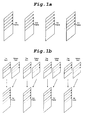
- the video scanning methods may greatly be classified into a progressive scan type as shown in Fig. la and an interlaced scan type as shown in Fig. 1b.
- a progressive scanning method of Fig. la a one-frame image is composed of lines which are sequentially scanned.
- a one-frame image is composed of lines which are alternately scanned.
- a one-frame image consists of two field images sampled at different times, or a top field image and a bottom field image.
- a video signal should be coded in a field unit as well as in a frame unit for the efficient coding of the field images.
- chrominance shape information is extracted by sub-sampling luminance shape information of the video signal in consideration of a sampling frequency ratio of luminance signal Y to chrominance signals Cb and Cr of chrominance signals. For example, considering the object-based vide codec, only the luminance shape information is inputted and transmitted to indicate a region in a frame and the chrominance shape information is extracted on the basis of the luminance shape information by virtue of an appropriate sub-sampling technique.
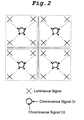
- a sampling frequency ratio of luminance signal Y to chrominance signals Cb and Cr is 4:2:0, as shown in Fig. 2.
- the total number of chrominance pixels is 1/4 that of luminance pixels (because the amount of chrominance data is reduced by 1/2, respectively, in horizontal and vertical directions).
- one chrominance component i.e., Cb or Cr
- This luminance-to-chrominance ratio must identically be applied to the extraction of chrominance shape information used in coding the chrominance signals.
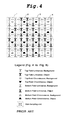
- a conservative chrominance shape sub-sampling method is used to extract chrominance shape information as shown in Fig. 4 with respect to luminance shape information as shown in Fig. 3 regardless of a video scanning type.
- a conventional conservative sub-sampling method as shown in Fig. 4, four adjacent luminance shape pixels(also designated as alpha pixel) surrounding a chrominance pixel corresponding to chrominance shape information to be extracted and nearest to the chrominance shape pixel are set to a sub-sampling unit. If all of the four luminance shape pixels are background pixels as in sub-sampling units 1 and 4, the corresponding chrominance shape pixel is determined as background shape pixel. In the case where at least one of the four luminance shape pixels is an object pixel as in sub-sampling units 2 and 3, the corresponding chrominance shape pixel is determined as object shape pixel.
- Fig. 5a shows an arrangement of chrominance shape information extracted with respect to the luminance shape information of Fig. 3 by the conventional conservative sub-sampling method, where " ⁇ " indicates background shape pixel and " ⁇ " indicates object shape pixel.
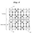
- Fig. 6 shows color bleeding portions appearing when the result extracted by the conventional conservative sub-sampling method in Fig. 4 is projected on a screen in an interlaced scanning manner.
- a color bleeding phenomenon occurs in which there are present portions 91, 92 and 93 with luminance components and no chrominance component corresponding thereto and a portion 94 with a chrominance component and no luminance component corresponding thereto.
- Such a sampling error of chrominance shape information results in the occurrence of an error in extracting the chrominance shape information.
- a chrominance signal of a background may be processed as that of an object. This has no effect on an objective picture quality, but it results in a significant degradation in subjective picture quality because the background signal is shown in the object.
- the picture quality of a video signal may be estimated in a quantitative manner based on a signal-to-noise ratio (SNR) or in a qualitative manner based on human visual sense.
- SNR signal-to-noise ratio
- the former is called the objective picture quality and the latter is called the subjective picture quality.
- the subjective picture quality is estimated qualitatively according to a difference between human visual impressions on image regions in a frame.
- the subjective picture quality cannot be estimated in such a quantitative manner as the SNR, but it is as important as the objective picture quality in estimating the performance of video processing techniques or units.
- a method is keenly required which is capable of extracting accurate chrominance shape information.
- the present invention has been made in view of the above problem, and it is an object of the present invention to provide a method of accurately extracting chrominance shape information for an interlaced scan type image, in which the chrominance shape information is sub-sampled in consideration of a characteristic of the interlaced scan type image.
- a method of extracting chrominance shape information for an interlaced scan type image comprising the step of setting, to one sub-sampling unit, every four adjacent luminance shape pixels in two lines of the same type field of an interlaced scan type image signal, and extracting the chrominance shape information on the basis of the four adjacent luminance shape pixels in each of the sub-sampling units.
- an apparatus for extracting chrominance shape information for an interlaced scan type image comprising a field separator for separating input luminance shape information into top and bottom fields; a top field sub-sampler for extracting chrominance shape information on the basis of luminance shape pixels in two lines of top field; a bottom field sub-sampler for extracting chrominance shape information on the basis of luminance shape pixels in two lines of bottom field; and frame reconstruction means for reconstructing the chrominance shape of a frame based on the chrominance shape information extracted by the top and bottom field sub-samplers.
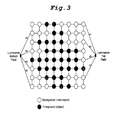
- Fig. 3 shows an example of arrangement of luminance shape information in one block (8 pixels / line x 8 lines) of an interlaced scan type image with arbitrary shape information.
- a one-frame image consists of two field images sampled at different times, or a top field image and a bottom field image.
- a chrominance shape information extraction method of the present invention does not employ a conventional conservative sub-sampling method but a new sub-sampling method of performing a sub-sampling operation using two lines of the same type field.
- chrominance shape information is extracted on the basis of four adjacent luminance shape pixels in two lines of the same type field by the chrominance shape information extraction method of the present invention.
- the chrominance shape information extraction method of the present invention is used in the current MPEG-4 video standard.
- Fig. 9 is a flowchart illustrating the chrominance shape information extraction method of the present invention. As shown in this drawing, it is first checked whether a desired chrominance pixel corresponding to chrominance shape information to be extracted belongs to the top field or bottom field. If the desired chrominance shape pixel belongs to the top field, four (2 pixels / line x 2 lines or 2x2) adjacent luminance shape pixels in the top field nearest thereto, are set to one sub-sampling unit at step S1. To the contrary, in the case where the desired chrominance shape pixel belongs to the bottom field, four (2x2) adjacent luminance shape pixels in the bottom field nearest thereto, are set to one sub-sampling unit at step S2.
- the desired chrominance shape pixel is determined as an object pixel at step S3.
- the desired chrominance shape pixel is determined as a background pixel at step S4.
- the chrominance shape information, extracted from the luminance shape information in this manner maybe defined in the form of a matrix based on various logic values, each of which indicates whether the corresponding chrominance shape pixel is an object pixel or a background pixel.
- the object shape information may be represented by either a binary value 1 or a gray scale value greater than 0, which indicates actual video data to be coded by a coder.
- the sum or average of logic values of the four adjacent luminance shape pixels in each sub-sampling unit may be used for the extraction of chrominance shape information.
- the sum or average of logic values is compared with a predetermined threshold value.
- the chrominance shape information is determined as object shape information if the sum or average exceeds the threshold value and as background shape information if not so.
- the threshold value maybe either a binary value 0 or a gray scale value selected according to a user's intention.
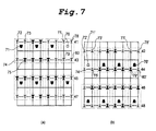
- Figs. 7a and 7b illustrate a luminance -chrominance shape information relation when chrominance shape information is extracted with respect to the luminance shape information of Fig. 3 by the chrominance shape information extraction method of the present invention.
- chrominance shape information is extracted on the basis of four luminance shape pixels in each sub-sampling unit.
- a chrominance pixel corresponding to chrominance shape information to be extracted is present in the top field, four adjacent luminance shape pixels in the top field, nearest thereto, are used to extract the chrominance shape information. If at least one of the four luminance shape pixels is an object pixel, the chrominance shape pixel is determined as object pixel.
- a chrominance shape pixel 71 corresponding to chrominance shape information to be extracted is present in the top field
- four (2x2) adjacent luminance shape pixels 72, 73, 74 and 75 on the first and the second lines 41 and 43 out of pixel lines 41, 43, 45 and 47 in the top field, surrounding the chrominance shape pixel 71 and nearest thereto are set to a sub-sampling unit. Because one 75 of the four luminance shape pixels 72-75 in the sub-sampling unit is an object pixel, the chrominance shape pixel 71 is determined as an object pixel. As a result, object shape information is extracted as the chrominance shape information. Then, chrominance shape information of the next chrominance shape pixel is extracted in the same manner.
- a chrominance shape pixel 76 in Fig. 7a In case of a chrominance shape pixel 76 in Fig. 7a, four adjacent luminance shape pixels 77, 78, 79 and 80 on the first and the second lines 41 and 43 in the top field, surrounding the chrominance shape pixel 76 and nearest thereto, are set to a sub-sampling unit. Because all of the four luminance shape pixels 77-80 in the sub-sampling unit are background pixels, the chrominance shape pixel 76 is determined as a background pixel. As a result, background shape information is extracted as the chrominance shape information. Then, chrominance shape information of the next chrominance shape information pixel is extracted in the same manner. Fig.
- FIG. 8 shows an arrangement of luminance and chrominance shape information pixels based on scanning time when chrominance shape information is extracted with respect to the interlaced scan type image with the luminance shape information of Fig. 3 by the chrominance shape information extraction method of the present invention.
- the top field in which the extracted chrominance shape information and the luminance shape information are arranged is shown above a center partition line 101.
- a chrominance shape pixel 71' corresponding to chrominance shape information to be extracted is present in the bottom field, four adjacent luminance shape pixels 72', 73', 74' and 75' on the first and the second lines 42 and 44 out of pixel lines 42, 44, 46 and 48 in the bottom field, surrounding the chrominance shape pixel 71' and nearest thereto, are set to a sub-sampling unit. Because all of the four luminance shape pixels 72'-75' in the sub-sampling unit are background pixels, the chrominance shape pixel 71' is determined as a background pixel. As a result, background shape information is extracted as the chrominance shape information. Then, chrominance shape information of the next chrominance shape pixel is extracted in the same manner.
- a chrominance shape pixel 76' corresponding to chrominance shape information to be extracted is present in the bottom field, four adjacent luminance shape pixels 77', 78', 79' and 80' on the first and the second lines 42 and 44 in the bottom field, surrounding the chrominance shape pixel 76' and nearest thereto, are set to a sub-sampling unit. Because one 79' of the four luminance shape pixels 77'-80' in the sub-sampling unit is an object pixel, the chrominance shape pixel 76' is determined as an object pixel. As a result, object shape information is extracted as the chrominance shape information. Then, chrominance shape information of the next chrominance shape pixel is extracted in the same manner. In Fig. 8, the bottom field in which the extracted chrominance shape information and the luminance shape information are arranged is shown below the center partition line 101.
- an apparatus for extracting chrominance shape information for an interlaced scan type image comprises sub-sampling means for extracting the chrominance shape information on the basis of four adjacent luminance shape pixels in two lines of the same type field of an interlaced scanned video signal.
- an apparatus for extracting chrominance shape information for an interlaced scan type image comprises means for setting, to one sub-sampling unit, every four adjacent luminance shape pixels in two lines of the same type field of an interlaced scan type image signal, and sub-sampling means for extracting chrominance shape information corresponding to an object, if at least one of the four luminance shape pixels in each of the sub-sampling units is an object pixel.
- the chrominance shape information extraction method and apparatus of the present invention is used in an MPEG-4 video compression coder and decoder for the object-based process. Further, the present method and apparatus are applicable to a content creation field where the user extracts and manipulates a desired region (object) in the entire image.
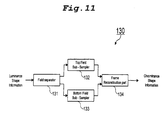
- Fig. 10 shows an embodiment of an object-based video compression coder/decoder system to which the chrominance shape information extraction method of the present invention is applied.
- the coder/decoder system comprises a coder 100 including a preprocessor 110, shape coding part 120, chrominance shape information extracting part 130, motion estimation/compensation part 140, texture coding part 160, subtracter 150, adder 170, previous reconstructed object information memory 180 and multiplexer(MUX) 190; a transmission medium 200 ; and a decoding part 300 including shape decoding part 320, chrominance shape information extracting part 330, motion decoding/motion compensation part 350, texture decoding part 340, adder 360, previous reconstructed object information memory 370, demultiplexer (DEMUX) 310 and reconstructed object composition part 380.
- a coder 100 including a preprocessor 110, shape coding part 120, chrominance shape information extracting part 130, motion estimation/compensation part 140, texture coding part 160
- the preprocessor 110 segments an input video signal into individual objects and represents the segmented object using its shape information and texture information, which are then applied to the shape coding part 120 and motion estimation/compensation part 140, respectively.
- the shape coding part 120 encodes the shape information of each object from the preprocessor 110 and generates reconstructed shape information.
- the reconstructed luminance shape information from the shape coding part 120 is transmitted to the chrominance shape information extracting part 130, motion estimation/compensation part 140 and texture coding part 160, thereby allowing them to perform their operations in the unit of objects.
- Another output from the shape coding part 120, or a luminance shape information bitstream, is applied to the multiplexer 190.
- the chrominance shape information extracting part 130 also receives picture type information. This information indicates whether the input video signal is generated by progressive scan type or interlaced scan type. If a given picture has a frame format of the progressive scan type, the chrominance shape information extracting part 130 performs a conventional conservative chrominance shape sub-sampling operation with respect to the luminance shape information from the shape coding part 120. However, in the case where the given picture has a field format of the interlaced scan type, the chrominance shape information extracting part 130 performs the chrominance shape information extraction method of the present invention with respect to the luminance shape information from the shape coding part 120.
- the chrominance shape information extracting part 130 comprises a field separator 131 for separating the luminance shape information from the shape coding part 120 into top and bottom fields, a top field sub-sampler 132 for setting every four adjacent luminance shape pixels in two lines of top field to one sub-sampling unit and extracting chrominance shape information corresponding to an object, if at least one of the four luminance shape pixels in each of the sub-sampling units is an object pixel, a bottom field sub-sampler 133 for setting every four adjacent luminance shape pixels in two lines of bottom field to one sub-sampling unit and extracting chrominance shape information corresponding to an object, if at least one of the four luminance shape pixels in each of the sub-sampling units is an object pixel, and a frame reconstruction part 134 for reconstructing the chrominance shape of a frame
- Each of the top and the bottom field sub-samplers 132 and 133 includes means for setting every four adjacent luminance shape pixels in two lines of the same type field to one sub-sampling unit, and sub-sampling means for extracting chrominance shape information corresponding to an object, if at least one of the four luminance shape pixels in each of the sub-sampling units is an object pixel.
- a motion estimation unit in the motion estimation/compensation part 140 estimates motion information of the current object texture information by comparing texture information of the current object based on the shape information from the shape coding part 120 with texture information of the previous object stored in the previous reconstructed object information memory 180.
- the motion information estimated by the motion estimation unit is fed to a motion compensation unit in the motion estimation/compensation part 140 for motion compensated prediction. Further, the estimated motion information is efficiently encoded in the motion estimation/compensation part 140 and then transmitted to the multiplexer 190 in the form of a motion information bitstream.
- the motion compensation unit performs a motion compensated prediction operation on the basis of the motion information estimated by the motion estimation unit and the previous object texture information from the previous reconstructed object information memory 180.
- the subtracter 150 obtains a prediction error, or a difference between input texture information of the current object to be coded and motion compensated prediction texture information from the motion compensation unit.
- the prediction error obtained by the subtracter 150 is encoded by the texture coding part 160 which then transmits a texture information bitstream to the multiplexer 190.
- the texture coding part 160 also supplies a reconstructed prediction error signal to the adder 170 which adds it to a motion compensated prediction signal from the motion compensation unit to produce reconstructed texture information of the corresponding object.
- the reconstructed texture information from the adder 170 is stored in the previous reconstructed object information memory 180 so that it can be used for the coding of the subsequent input object.
- the multiplexer 190 multiplexes the luminance shape information bitstream from the shape coding part 120, motion information bitstream from the motion estimation/compensation part 140 and texture information bitstream from the texture coding part 160 and then transmits the resultant video bitstream to the decoding part 300 via the transmission medium 200.
- the demultiplexer 310 separates the video bitstream transmitted via the transmission medium 200 into the motion information bitstream, luminance shape information bitstream, texture information bitstream and picture type information bitstream.
- the shape decoding part 320 receives the luminance shape information bitstream from the demultiplexer 310 and provides reconstructed shape information to the chrominance shape information extracting part 330, motion compensation part 350 and texture decoding part 340 for the object-based decoding process. It should be noted herein that only luminance shape information is transmitted via the transmission medium 200.
- the chrominance shape information extracting part 330 extracts chrominance shape information on the basis of the transmitted luminance shape information.
- the chrominance shape information extracting part 330 is substantially the same in construction and operation as the chrominance shape information extracting part 130 in the coder 100.
- the chrominance shape information extracted by the chrominance shape information extracting part 330 is inputted to the texture decoding part 340 and motion decoding/compensation part 350.
- the texture decoding part 340 decodes the texture information bitstream using the reconstructed shape information from the shape decoding part 320 to provide reconstructed texture information.
- the motion decoding unit of motion decoding/compensation part 350 decodes motion information from the motion information bitstream.
- the motion compensation unit of motion decoding/compensation part 350 performs a motion compensated prediction operation on the basis of motion information from a motion decoding part and previous texture information stored in the previous reconstructed object information memory 370.
- the reconstructed shape information from the shape decoding part 320 is, of course, applied to the motion compensation part 350 because the motion compensated prediction operation must be performed in the unit of objects.
- the adder 360 adds a motion compensated prediction signal from the motion compensation part 350 to the reconstructed texture information from the texture decoding part 340 to reconstruct the corresponding object.
- This reconstructed object is stored in the previous reconstructed object information memory 370 so that it can be used for the coding of the subsequent frames.
- the reconstructed object from the adder 360 is also combined with other objects by the reconstructed object composition part 380 for the reproduction of a video signal.
- the chrominance shape information extraction method and apparatus are adapted to set, to one sub-sampling unit, every four adjacent luminance shape pixels in two lines of the same type field of an interlaced scan type image signal of field format and extract chrominance shape information on the basis of the four luminance shape pixels in each of the sub-sampling units. Therefore, the present invention overcomes a color bleeding problem in a conventional chrominance shape information extraction method considering no characteristic of an interlaced scan type image. As a result, the present invention has the effect of significantly improving a subjective picture quality.
Landscapes
- Engineering & Computer Science (AREA)
- Multimedia (AREA)
- Signal Processing (AREA)
- Compression Or Coding Systems Of Tv Signals (AREA)
- Color Television Systems (AREA)
- Image Analysis (AREA)
- Processing Of Color Television Signals (AREA)
- Manufacture Or Reproduction Of Printing Formes (AREA)
- Compression Of Band Width Or Redundancy In Fax (AREA)
Priority Applications (2)
| Application Number | Priority Date | Filing Date | Title |
|---|---|---|---|
| DK99104390T DK0940995T3 (da) | 1998-03-05 | 1999-03-04 | Fremgangsmåde og apparat til uddragning af krominanskonturinformation for billeder af linjespringsscanningstypen |
| SI9930778T SI0940995T1 (en) | 1998-03-05 | 1999-03-04 | Method and apparatus for extracting chrominance shape information for interlaced scan type image |
Applications Claiming Priority (4)
| Application Number | Priority Date | Filing Date | Title |
|---|---|---|---|
| KR19980007374 | 1998-03-05 | ||
| KR9807374 | 1998-03-05 | ||
| KR9904674 | 1999-02-10 | ||
| KR1019990004674A KR100374717B1 (ko) | 1998-03-05 | 1999-02-10 | 비월주사방식 영상을 위한 색차신호 모양정보 추출방법 및 장치 |
Publications (3)
| Publication Number | Publication Date |
|---|---|
| EP0940995A2 true EP0940995A2 (de) | 1999-09-08 |
| EP0940995A3 EP0940995A3 (de) | 2002-10-23 |
| EP0940995B1 EP0940995B1 (de) | 2005-02-16 |
Family
ID=37416804
Family Applications (1)
| Application Number | Title | Priority Date | Filing Date |
|---|---|---|---|
| EP99104390A Expired - Lifetime EP0940995B1 (de) | 1998-03-05 | 1999-03-04 | Verfahren und Gerät für die Herausziehung von Farbkonturinformation aus Videohalbbildern |
Country Status (10)
| Country | Link |
|---|---|
| US (1) | US7899112B1 (de) |
| EP (1) | EP0940995B1 (de) |
| JP (1) | JP3439146B2 (de) |
| KR (1) | KR100374717B1 (de) |
| AT (1) | ATE289467T1 (de) |
| DE (1) | DE69923725T2 (de) |
| DK (1) | DK0940995T3 (de) |
| ES (1) | ES2236979T3 (de) |
| PT (1) | PT940995E (de) |
| SI (1) | SI0940995T1 (de) |
Cited By (2)
| Publication number | Priority date | Publication date | Assignee | Title |
|---|---|---|---|---|
| WO2010028107A1 (en) * | 2008-09-07 | 2010-03-11 | Dolby Laboratories Licensing Corporation | Conversion of interleaved data sets, including chroma correction and/or correction of checkerboard interleaved formatted 3d images |
| US20100171817A1 (en) * | 2009-01-07 | 2010-07-08 | Dolby Laboratories Licensing Corporation | Conversion, correction, and other operations related to multiplexed data sets |
Families Citing this family (2)
| Publication number | Priority date | Publication date | Assignee | Title |
|---|---|---|---|---|
| JP5033375B2 (ja) * | 2006-08-11 | 2012-09-26 | 株式会社 ペンジュラム | 保護回路及び負荷電流検出回路 |
| WO2014196118A1 (ja) * | 2013-06-04 | 2014-12-11 | 三菱電機株式会社 | 画像符号化装置、画像解析装置、画像符号化方法及び画像解析方法 |
Family Cites Families (17)
| Publication number | Priority date | Publication date | Assignee | Title |
|---|---|---|---|---|
| DE2644706C3 (de) * | 1976-10-04 | 1985-12-05 | Robert Bosch Gmbh, 7000 Stuttgart | System zur Übertragung bzw. Speicherung eines Farbfernsehsignals |
| KR940002196B1 (ko) * | 1990-03-27 | 1994-03-18 | 미쯔비시덴끼 가부시끼가이샤 | 움직임 적응형 휘도신호 색신호 분리 필터 |
| JP2991833B2 (ja) * | 1991-10-11 | 1999-12-20 | 松下電器産業株式会社 | インターレス走査ディジタルビデオ信号の符号化装置及びその方法 |
| JP2936299B2 (ja) * | 1993-07-22 | 1999-08-23 | 日本テレビ放送網株式会社 | 信号伝送・記録、及び入力・出力方法 |
| US5712687A (en) * | 1996-04-25 | 1998-01-27 | Tektronix, Inc. | Chrominance resampling for color images |
| KR100209412B1 (ko) * | 1996-05-10 | 1999-07-15 | 전주범 | 비디오 신호의 유호 색차 성분 부호화 방법 |
| US5974172A (en) * | 1997-02-14 | 1999-10-26 | At&T Corp | Method and apparatus for coding segmented regions which may be transparent in video sequences for content-based scalability |
| US6208693B1 (en) * | 1997-02-14 | 2001-03-27 | At&T Corp | Chroma-key for efficient and low complexity shape representation of coded arbitrary video objects |
| US6005980A (en) * | 1997-03-07 | 1999-12-21 | General Instrument Corporation | Motion estimation and compensation of video object planes for interlaced digital video |
| US6057884A (en) * | 1997-06-05 | 2000-05-02 | General Instrument Corporation | Temporal and spatial scaleable coding for video object planes |
| US6002812A (en) * | 1997-07-10 | 1999-12-14 | Samsung Electronics Co., Ltd. | Interpolation method for binary image |
| JP3813320B2 (ja) * | 1997-08-27 | 2006-08-23 | 株式会社東芝 | 動きベクトル検出方法および装置 |
| US6532022B1 (en) * | 1997-10-15 | 2003-03-11 | Electric Planet, Inc. | Method and apparatus for model-based compositing |
| US6407735B2 (en) * | 1997-11-13 | 2002-06-18 | Crump Group Inc. | Method for generating surface representations of objects from layered data |
| US5973743A (en) * | 1997-12-02 | 1999-10-26 | Daewoo Electronics Co., Ltd. | Mode coding method and apparatus for use in an interlaced shape coder |
| US6137837A (en) * | 1998-01-23 | 2000-10-24 | Motorola, Inc. | Motion estimation for digital video with reduced number of search window pixels |
| GB2336058B (en) * | 1998-04-02 | 2002-03-27 | Daewoo Electronics Co Ltd | Apparatus and method for adaptively coding an image signal |
-
1999
- 1999-02-10 KR KR1019990004674A patent/KR100374717B1/ko not_active Expired - Fee Related
- 1999-03-03 US US09/261,246 patent/US7899112B1/en not_active Expired - Fee Related
- 1999-03-04 JP JP05690399A patent/JP3439146B2/ja not_active Expired - Fee Related
- 1999-03-04 SI SI9930778T patent/SI0940995T1/xx unknown
- 1999-03-04 DK DK99104390T patent/DK0940995T3/da active
- 1999-03-04 ES ES99104390T patent/ES2236979T3/es not_active Expired - Lifetime
- 1999-03-04 DE DE1999623725 patent/DE69923725T2/de not_active Expired - Lifetime
- 1999-03-04 AT AT99104390T patent/ATE289467T1/de active
- 1999-03-04 PT PT99104390T patent/PT940995E/pt unknown
- 1999-03-04 EP EP99104390A patent/EP0940995B1/de not_active Expired - Lifetime
Cited By (5)
| Publication number | Priority date | Publication date | Assignee | Title |
|---|---|---|---|---|
| WO2010028107A1 (en) * | 2008-09-07 | 2010-03-11 | Dolby Laboratories Licensing Corporation | Conversion of interleaved data sets, including chroma correction and/or correction of checkerboard interleaved formatted 3d images |
| KR101258106B1 (ko) | 2008-09-07 | 2013-04-25 | 돌비 레버러토리즈 라이쎈싱 코오포레이션 | 크로마 정정 및/또는 체커보드 인터리브된 포맷의 3d 이미지들의 정정을 포함하는 인터리브된 데이터 세트들의 컨버젼 |
| US9264690B2 (en) | 2008-09-07 | 2016-02-16 | Dolby Laboratories Licensing Corporation | Conversion of interleaved data sets, including chroma correction and/or correction of checkerboard interleaved formatted 3D images |
| US20100171817A1 (en) * | 2009-01-07 | 2010-07-08 | Dolby Laboratories Licensing Corporation | Conversion, correction, and other operations related to multiplexed data sets |
| US9055278B2 (en) | 2009-01-07 | 2015-06-09 | Dolby Laboratories Licensing Corporation | Conversion, correction, and other operations related to multiplexed data sets |
Also Published As
| Publication number | Publication date |
|---|---|
| EP0940995B1 (de) | 2005-02-16 |
| SI0940995T1 (en) | 2005-08-31 |
| US7899112B1 (en) | 2011-03-01 |
| KR19990077416A (ko) | 1999-10-25 |
| PT940995E (pt) | 2005-04-29 |
| KR100374717B1 (ko) | 2003-03-04 |
| JP3439146B2 (ja) | 2003-08-25 |
| ES2236979T3 (es) | 2005-07-16 |
| JPH11331867A (ja) | 1999-11-30 |
| DE69923725D1 (de) | 2005-03-24 |
| DE69923725T2 (de) | 2006-01-05 |
| EP0940995A3 (de) | 2002-10-23 |
| ATE289467T1 (de) | 2005-03-15 |
| DK0940995T3 (da) | 2005-04-11 |
Similar Documents
| Publication | Publication Date | Title |
|---|---|---|
| CN110324626B (zh) | 一种面向物联网监控的双码流人脸分辨率保真的视频编解码方法 | |
| DE69839100T2 (de) | Verbesserte Videokodierung unter Verwendung von adaptiven Blockparametern für kodierte/unkodierte Blöcke | |
| US6546142B2 (en) | Motion image coding apparatus for performing hierarchical coding | |
| US7362804B2 (en) | Graphical symbols for H.264 bitstream syntax elements | |
| US5438374A (en) | System and method for filtering video signals | |
| US6577679B1 (en) | Method and apparatus for transcoding coded picture signals from object-based coding to block-based coding | |
| US20050036759A1 (en) | Efficient motion vector coding for video compression | |
| EP1289301A1 (de) | Verfahren und vorrichtung zur bildkodierung | |
| US6069976A (en) | Apparatus and method for adaptively coding an image signal | |
| JP4033554B2 (ja) | インタレース形状情報符号化方法 | |
| KR100367831B1 (ko) | 영상의 색차신호 필터링 방법 및 장치 | |
| US20070086666A1 (en) | Compatible interlaced sdtv and progressive hdtv | |
| US20060274833A1 (en) | Text recognition during video compression | |
| EP0939554A2 (de) | Verfahren und Vorrichtung zur Kodierung eines Transparenzsignals | |
| EP0940995B1 (de) | Verfahren und Gerät für die Herausziehung von Farbkonturinformation aus Videohalbbildern | |
| US20070274687A1 (en) | Video Signal Encoder, A Video Signal Processor, A Video Signal Distribution System And Methods Of Operation Therefor | |
| US7426311B1 (en) | Object-based coding and decoding apparatuses and methods for image signals | |
| JP2868445B2 (ja) | 動画像圧縮方法および装置 | |
| Soryani et al. | Segmented coding of digital image sequences | |
| KR100559713B1 (ko) | 격행주사를 위한 색상 정보 부호화/복호화 장치 및 그 방법 | |
| Guaragnella et al. | Object oriented motion estimation by sliced-block matching algorithm | |
| Sakaida et al. | Moving object extraction using background difference and region growing with a spatiotemporal watershed algorithm | |
| Lebègue et al. | Video compression for the grand alliance: A historical perspective | |
| WO1999059342A1 (en) | Method and system for mpeg-2 encoding with frame partitioning | |
| Pronina et al. | Improving MPEG performance using frame partitioning |
Legal Events
| Date | Code | Title | Description |
|---|---|---|---|
| PUAI | Public reference made under article 153(3) epc to a published international application that has entered the european phase |
Free format text: ORIGINAL CODE: 0009012 |
|
| AK | Designated contracting states |
Kind code of ref document: A2 Designated state(s): AT BE CH CY DE DK ES FI FR GB GR IE IT LI LU MC NL PT SE |
|
| AX | Request for extension of the european patent |
Free format text: AL;LT;LV;MK;RO;SI |
|
| RAP1 | Party data changed (applicant data changed or rights of an application transferred) |
Owner name: HYUNDAI ELECTRONICS INDUSTRIES CO., LTD. |
|
| K1C1 | Correction of patent application (title page) published |
Effective date: 19990908 |
|
| RAP1 | Party data changed (applicant data changed or rights of an application transferred) |
Owner name: HYNIX SEMICONDUCTOR INC. |
|
| RAP1 | Party data changed (applicant data changed or rights of an application transferred) |
Owner name: HYUNDAI CURITEL, INC. |
|
| PUAL | Search report despatched |
Free format text: ORIGINAL CODE: 0009013 |
|
| AK | Designated contracting states |
Kind code of ref document: A3 Designated state(s): AT BE CH CY DE DK ES FI FR GB GR IE IT LI LU MC NL PT SE |
|
| AX | Request for extension of the european patent |
Free format text: AL;LT;LV;MK;RO;SI |
|
| RIC1 | Information provided on ipc code assigned before grant |
Free format text: 7H 04N 9/64 A, 7H 04N 7/26 B, 7H 04N 9/77 B |
|
| 17P | Request for examination filed |
Effective date: 20030130 |
|
| AKX | Designation fees paid |
Designated state(s): AT BE CH CY DE DK ES FI FR GB GR IE IT LI LU MC NL PT SE |
|
| AXX | Extension fees paid |
Extension state: SI Payment date: 20030130 Extension state: RO Payment date: 20030130 Extension state: MK Payment date: 20030130 Extension state: LV Payment date: 20030130 Extension state: LT Payment date: 20030130 Extension state: AL Payment date: 20030130 |
|
| GRAP | Despatch of communication of intention to grant a patent |
Free format text: ORIGINAL CODE: EPIDOSNIGR1 |
|
| GRAS | Grant fee paid |
Free format text: ORIGINAL CODE: EPIDOSNIGR3 |
|
| GRAA | (expected) grant |
Free format text: ORIGINAL CODE: 0009210 |
|
| AK | Designated contracting states |
Kind code of ref document: B1 Designated state(s): AT BE CH CY DE DK ES FI FR GB GR IE IT LI LU MC NL PT SE |
|
| AX | Request for extension of the european patent |
Extension state: AL LT LV MK RO SI |
|
| REG | Reference to a national code |
Ref country code: GB Ref legal event code: FG4D |
|
| REG | Reference to a national code |
Ref country code: CH Ref legal event code: EP |
|
| REG | Reference to a national code |
Ref country code: IE Ref legal event code: FG4D |
|
| REF | Corresponds to: |
Ref document number: 69923725 Country of ref document: DE Date of ref document: 20050324 Kind code of ref document: P |
|
| REG | Reference to a national code |
Ref country code: DK Ref legal event code: T3 |
|
| REG | Reference to a national code |
Ref country code: PT Ref legal event code: SC4A Free format text: AVAILABILITY OF NATIONAL TRANSLATION Effective date: 20050223 |
|
| REG | Reference to a national code |
Ref country code: CH Ref legal event code: NV Representative=s name: ISLER & PEDRAZZINI AG |
|
| REG | Reference to a national code |
Ref country code: GR Ref legal event code: EP Ref document number: 20050401195 Country of ref document: GR |
|
| REG | Reference to a national code |
Ref country code: SE Ref legal event code: TRGR |
|
| REG | Reference to a national code |
Ref country code: ES Ref legal event code: FG2A Ref document number: 2236979 Country of ref document: ES Kind code of ref document: T3 |
|
| PLBE | No opposition filed within time limit |
Free format text: ORIGINAL CODE: 0009261 |
|
| STAA | Information on the status of an ep patent application or granted ep patent |
Free format text: STATUS: NO OPPOSITION FILED WITHIN TIME LIMIT |
|
| ET | Fr: translation filed | ||
| 26N | No opposition filed |
Effective date: 20051117 |
|
| REG | Reference to a national code |
Ref country code: CH Ref legal event code: PCAR Free format text: ISLER & PEDRAZZINI AG;POSTFACH 1772;8027 ZUERICH (CH) |
|
| REG | Reference to a national code |
Ref country code: FR Ref legal event code: PLFP Year of fee payment: 17 |
|
| REG | Reference to a national code |
Ref country code: FR Ref legal event code: PLFP Year of fee payment: 18 |
|
| REG | Reference to a national code |
Ref country code: DE Ref legal event code: R082 Ref document number: 69923725 Country of ref document: DE Representative=s name: KUHNEN & WACKER PATENT- UND RECHTSANWALTSBUERO, DE Ref country code: DE Ref legal event code: R081 Ref document number: 69923725 Country of ref document: DE Owner name: PANTECH INC., KR Free format text: FORMER OWNER: HYUNDAI CURITEL, INC., ICHON, KYOUNGKI, KR |
|
| REG | Reference to a national code |
Ref country code: CH Ref legal event code: PUE Owner name: PANTECH INC., KR Free format text: FORMER OWNER: PANTECH CO., LTD., KR Ref country code: CH Ref legal event code: PFUS Owner name: PANTECH CO., LTD., KR Free format text: FORMER OWNER: PANTECH AND CURITEL COMMUNICATIONS INC., KR Ref country code: CH Ref legal event code: PFA Owner name: PANTECH AND CURITEL COMMUNICATIONS INC., KR Free format text: FORMER OWNER: CURITEL COMMUNICATIONS INC., KR Ref country code: CH Ref legal event code: PFA Owner name: CURITEL COMMUNICATIONS INC., KR Free format text: FORMER OWNER: HYUNDAI CURITEL, INC., KR Ref country code: CH Ref legal event code: NV Representative=s name: SCHNEIDER FELDMANN AG PATENT- UND MARKENANWAEL, CH |
|
| REG | Reference to a national code |
Ref country code: ES Ref legal event code: PC2A Owner name: PANTECH INC. Effective date: 20170130 |
|
| REG | Reference to a national code |
Ref country code: NL Ref legal event code: PD Owner name: PANTECH PROPERTY MANAGEMENT INC.; KR Free format text: DETAILS ASSIGNMENT: CHANGE OF OWNER(S), MERGE; FORMER OWNER NAME: PANTECH & CURITEL COMMUNICATIONS INC. Effective date: 20170404 Ref country code: NL Ref legal event code: HC Owner name: PANTECH & CURITEL COMMUNICATIONS INC.; KR Free format text: DETAILS ASSIGNMENT: CHANGE OF OWNER(S), CHANGE OF OWNER(S) NAME; FORMER OWNER NAME: HYUNDAI CURITEL, INC. Effective date: 20170404 |
|
| REG | Reference to a national code |
Ref country code: SI Ref legal event code: SP73 Owner name: PANTECH INC.; KR Effective date: 20170531 |
|
| REG | Reference to a national code |
Ref country code: SI Ref legal event code: SP73 Owner name: PANTECH INC.; KR Effective date: 20170602 |
|
| REG | Reference to a national code |
Ref country code: NL Ref legal event code: PD Owner name: PANTECH INC.; KR Free format text: DETAILS ASSIGNMENT: CHANGE OF OWNER(S), MERGE, DEMERGE; FORMER OWNER NAME: PANTECH PROPERTY MANAGEMENT INC. Effective date: 20170807 Ref country code: FR Ref legal event code: CD Owner name: PANTECH INC., KR Effective date: 20170719 |
|
| REG | Reference to a national code |
Ref country code: FR Ref legal event code: TP Owner name: PANTECH INC., KR Effective date: 20170719 Ref country code: FR Ref legal event code: CD Owner name: PANTECH INC., KR Effective date: 20170719 Ref country code: FR Ref legal event code: CA Effective date: 20170719 |
|
| REG | Reference to a national code |
Ref country code: FR Ref legal event code: PLFP Year of fee payment: 19 |
|
| PGFP | Annual fee paid to national office [announced via postgrant information from national office to epo] |
Ref country code: NL Payment date: 20170830 Year of fee payment: 19 Ref country code: LU Payment date: 20170829 Year of fee payment: 19 |
|
| PGFP | Annual fee paid to national office [announced via postgrant information from national office to epo] |
Ref country code: GR Payment date: 20170829 Year of fee payment: 19 Ref country code: MC Payment date: 20170831 Year of fee payment: 19 Ref country code: FI Payment date: 20170829 Year of fee payment: 19 Ref country code: ES Payment date: 20170913 Year of fee payment: 19 Ref country code: CH Payment date: 20170830 Year of fee payment: 19 Ref country code: DE Payment date: 20170829 Year of fee payment: 19 |
|
| PGFP | Annual fee paid to national office [announced via postgrant information from national office to epo] |
Ref country code: IE Payment date: 20170829 Year of fee payment: 19 Ref country code: SE Payment date: 20170830 Year of fee payment: 19 Ref country code: PT Payment date: 20170829 Year of fee payment: 19 Ref country code: BE Payment date: 20170830 Year of fee payment: 19 Ref country code: AT Payment date: 20170829 Year of fee payment: 19 Ref country code: DK Payment date: 20170830 Year of fee payment: 19 |
|
| REG | Reference to a national code |
Ref country code: AT Ref legal event code: PC Ref document number: 289467 Country of ref document: AT Kind code of ref document: T Owner name: PANTECH INC., KR Effective date: 20171017 |
|
| PGFP | Annual fee paid to national office [announced via postgrant information from national office to epo] |
Ref country code: CY Payment date: 20170830 Year of fee payment: 19 |
|
| REG | Reference to a national code |
Ref country code: GB Ref legal event code: 732E Free format text: REGISTERED BETWEEN 20180412 AND 20180418 |
|
| REG | Reference to a national code |
Ref country code: FR Ref legal event code: PLFP Year of fee payment: 20 |
|
| REG | Reference to a national code |
Ref country code: LT Ref legal event code: MM9D Effective date: 20180304 |
|
| REG | Reference to a national code |
Ref country code: DE Ref legal event code: R119 Ref document number: 69923725 Country of ref document: DE |
|
| REG | Reference to a national code |
Ref country code: DK Ref legal event code: EBP Effective date: 20180331 |
|
| PG25 | Lapsed in a contracting state [announced via postgrant information from national office to epo] |
Ref country code: CY Free format text: LAPSE BECAUSE OF NON-PAYMENT OF DUE FEES Effective date: 20180304 Ref country code: SE Free format text: LAPSE BECAUSE OF NON-PAYMENT OF DUE FEES Effective date: 20180305 Ref country code: PT Free format text: LAPSE BECAUSE OF NON-PAYMENT OF DUE FEES Effective date: 20180904 Ref country code: FI Free format text: LAPSE BECAUSE OF NON-PAYMENT OF DUE FEES Effective date: 20180304 |
|
| PGFP | Annual fee paid to national office [announced via postgrant information from national office to epo] |
Ref country code: FR Payment date: 20180906 Year of fee payment: 20 Ref country code: IT Payment date: 20180907 Year of fee payment: 20 |
|
| REG | Reference to a national code |
Ref country code: CH Ref legal event code: PL |
|
| REG | Reference to a national code |
Ref country code: NL Ref legal event code: MM Effective date: 20180401 |
|
| REG | Reference to a national code |
Ref country code: AT Ref legal event code: MM01 Ref document number: 289467 Country of ref document: AT Kind code of ref document: T Effective date: 20180304 |
|
| PG25 | Lapsed in a contracting state [announced via postgrant information from national office to epo] |
Ref country code: MC Free format text: LAPSE BECAUSE OF NON-PAYMENT OF DUE FEES Effective date: 20180403 |
|
| PGFP | Annual fee paid to national office [announced via postgrant information from national office to epo] |
Ref country code: GB Payment date: 20180906 Year of fee payment: 20 |
|
| REG | Reference to a national code |
Ref country code: SI Ref legal event code: KO00 Effective date: 20181008 |
|
| REG | Reference to a national code |
Ref country code: BE Ref legal event code: MM Effective date: 20180331 |
|
| REG | Reference to a national code |
Ref country code: IE Ref legal event code: MM4A |
|
| PG25 | Lapsed in a contracting state [announced via postgrant information from national office to epo] |
Ref country code: NL Free format text: LAPSE BECAUSE OF NON-PAYMENT OF DUE FEES Effective date: 20180401 Ref country code: LU Free format text: LAPSE BECAUSE OF NON-PAYMENT OF DUE FEES Effective date: 20180304 |
|
| PG25 | Lapsed in a contracting state [announced via postgrant information from national office to epo] |
Ref country code: DE Free format text: LAPSE BECAUSE OF NON-PAYMENT OF DUE FEES Effective date: 20181002 Ref country code: AT Free format text: LAPSE BECAUSE OF NON-PAYMENT OF DUE FEES Effective date: 20180304 Ref country code: IE Free format text: LAPSE BECAUSE OF NON-PAYMENT OF DUE FEES Effective date: 20180304 Ref country code: GR Free format text: LAPSE BECAUSE OF NON-PAYMENT OF DUE FEES Effective date: 20181003 |
|
| PG25 | Lapsed in a contracting state [announced via postgrant information from national office to epo] |
Ref country code: LI Free format text: LAPSE BECAUSE OF NON-PAYMENT OF DUE FEES Effective date: 20180331 Ref country code: CH Free format text: LAPSE BECAUSE OF NON-PAYMENT OF DUE FEES Effective date: 20180331 Ref country code: BE Free format text: LAPSE BECAUSE OF NON-PAYMENT OF DUE FEES Effective date: 20180331 |
|
| REG | Reference to a national code |
Ref country code: GB Ref legal event code: PE20 Expiry date: 20190303 |
|
| PG25 | Lapsed in a contracting state [announced via postgrant information from national office to epo] |
Ref country code: GB Free format text: LAPSE BECAUSE OF EXPIRATION OF PROTECTION Effective date: 20190303 |
|
| PG25 | Lapsed in a contracting state [announced via postgrant information from national office to epo] |
Ref country code: DK Free format text: LAPSE BECAUSE OF NON-PAYMENT OF DUE FEES Effective date: 20180331 Ref country code: PT Free format text: LAPSE BECAUSE OF EXPIRATION OF PROTECTION Effective date: 20190314 |
|
| REG | Reference to a national code |
Ref country code: ES Ref legal event code: FD2A Effective date: 20190904 |
|
| PG25 | Lapsed in a contracting state [announced via postgrant information from national office to epo] |
Ref country code: ES Free format text: LAPSE BECAUSE OF NON-PAYMENT OF DUE FEES Effective date: 20180305 |