EP0940792B1 - Procédé de détection de véhicules - Google Patents
Procédé de détection de véhicules Download PDFInfo
- Publication number
- EP0940792B1 EP0940792B1 EP99103249A EP99103249A EP0940792B1 EP 0940792 B1 EP0940792 B1 EP 0940792B1 EP 99103249 A EP99103249 A EP 99103249A EP 99103249 A EP99103249 A EP 99103249A EP 0940792 B1 EP0940792 B1 EP 0940792B1
- Authority
- EP
- European Patent Office
- Prior art keywords
- signal
- alarm
- confidence
- vehicle noise
- signals
- Prior art date
- Legal status (The legal status is an assumption and is not a legal conclusion. Google has not performed a legal analysis and makes no representation as to the accuracy of the status listed.)
- Expired - Lifetime
Links
Images
Classifications
-
- G—PHYSICS
- G08—SIGNALLING
- G08G—TRAFFIC CONTROL SYSTEMS
- G08G1/00—Traffic control systems for road vehicles
- G08G1/01—Detecting movement of traffic to be counted or controlled
- G08G1/04—Detecting movement of traffic to be counted or controlled using optical or ultrasonic detectors
Definitions
- the invention relates to a method for detecting itself a surveillance area approaching vehicles in the Preamble of claim 1 defined genus.
- Such a method is preferably used in wake-up devices used to serve autonomous surveillance systems of terrain areas on and / or to secure Terrain areas against the intrusion of objects, here Vehicles to activate (wake up) only when is reasonably certain that such objects in the Surveillance area appear and / or that the appearing objects also around the surveillance-specific Objects and not others.
- the wake up must be included false alarm rate is as low as possible, that the object is still within the radius of action of the Systems is located.
- a geophone and a microphone are used as sensors and their Output signals preprocessed in accordance with signaling technology.
- the pre-processed output signals of the microphone continuous signal peaks for specified time segments or impulses detected, and in the equally pre-processed Output signals of the geophone become signal peaks or -impulses eliminated at those places in same time pieces of the microphone output signal signal peaks or pulses occur.
- the through this pulse elimination adjusted time pieces of the geophone output signal becomes a predetermined maximum number of the largest signal peaks or -Pulses extracted and by means of the extracted signal peaks or pulses the likelihood of pedestrian detection rated.
- This process involves eliminating signatures in the geophone output signal, which is also in the microphone output signal occur, such sound events, e.g. removed air blasts, imposed on the detection of air in the medium Generate sound impulses, which in turn hit the ground couple and a similar signature in the geophone output signal evoke like the steps of the pedestrian.
- the Detection reliability is increased in that the Detection result no longer with a yes / no decision displayed, but in terms of its probability is evaluated so that the surgeon based on the Degree of probability or measure of confidence of the detection again the reliability of the detection result can include your own calculation.
- the invention has for its object a method for Detection of vehicles of the type mentioned above with high Detection probability and low false alarm rate create that without interpretation or evaluation by one Surgeon gets along, so it is fully autonomous, and only one relative requires simple signal processing so that it is in unattended wakeup devices that are a bulk item represent, can be used.
- the task is in a procedure in the preamble of Claim specified genus according to the invention by the Features in the characterizing part of claim 1 solved.
- the inventive method has the advantage that Independence of the alarm levels makes each alarm level easy regarding the required time and frequency range, the Realize method and scope for signal processing leaves.
- the exploitation of different physical characteristics in the sensor signals for detection in the different Wakeup levels lead to a significant improvement in Detection method with regard to its reliability Vehicle detection and robustness to interference and to a high level of functional reliability one with such a Process operated alarm device.
- the one in the individual Wakeup signals can be processed by a single or removed from multiple sensors.
- the exchange The sensors are problem-free, making the process easy can be adapted to the specifics of the area of application.
- the Linking the slave wake-up signals generated in each wake-up level to the actual detection or wake-up signal, the so-called Master wake-up signal, is based on simple heuristic Rules that are easily changed and reflect the specifics of the Field of application can be adapted and beyond are easy to implement. According to the requirements regarding the false alarm rate and the Detection probability based on the justifiable Effort can freely choose the number of wake-up levels available and different alarm levels can be combined differently. A wake-up device operating according to the method can thus be used easily on the requirements in one specific area of application both technically and in terms of price be tailored.
- Linking the slave wake-up signals to the master wake-up signal can e.g. by cascading the wake-up levels done so that each slave wake-up signal of a wake-up stage subsequent wake-up level activated and in that order last alarm stage generates the master alarm signal.
- the individual wake-up stages can also be operated in parallel be switched on at the same time, and their Slave wake-up signals are linked, the link weighted according to the confidence measures of the individual slave wake-up signals he follows. This has the advantage of being less Signal / interference ratios long detection ranges possible and the false alarm rate is kept low. additionally an early wake is possible.
- the method according to the invention is based on a Drawing shown device for performing the Process described in more detail below.
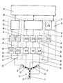
- the shows Drawing a block diagram of a according to the invention Process working, responsive to vehicle noise Wake-up device.
- the one shown in the drawing in the block diagram Wake-up device is used to activate or wake up autonomously Area monitoring systems for the Penetration of or being run over by vehicles of all kinds, the autonomous system being a reconnaissance system for capturing of troop movements or a control system, e.g. on Mine system, to destroy all or selected vehicles can be.
- That deployed together with the autonomous system in the field Wake-up device has an acoustic antenna 10 which three arranged at 120 ° to each other in a star shape Has antenna arms 11, 12 and 13. On each antenna arm 11 to 13 are three microphones 14 at a constant distance arranged from each other. At the star point of the three antenna arms 11 to 13 there is another microphone 14.
- a signal processing for the preparation and evaluation of the Output signals of the microphones 14 and for generating a Wake-up signal is in three individual wake-up levels 15, 16 and 17 split that work independently and qualitatively different characteristics that are significant for that Presence of vehicle noise is in them Extract and evaluate supplied signals and at sufficient confidence of the extracted characteristics Wake-up signal, the so-called slave wake-up signal.
- the slave wake-up signals the alarm levels 15 to 17 become functional connecting linking unit 18, which in turn the master wake-up signal is generated.
- the connection of the slave wake-up signals can be done in done in different ways.
- the wake-up stages 15 to 17 by the linking unit 18 connected in series, d. H. the slave wake-up signal Alarm level 15 is used to activate alarm level 16 and that Slave wake-up signal of wake-up level 16 to activate the wake-up level 17 used.
- the slave wake-up signal of the last wake-up stage 17 is then the master wake-up signal.
- the order of Activation of alarm levels 15 to 17 can be swapped become.
- the wake-up level with the lowest energy consumption (here alarm 15) first switched on and the subsequent stages with qualitative higher-quality signal processing and thus much larger Energy consumption only switched on when in each case previous wake-up stage another preliminary decision in Direction towards the probability of vehicle detection has been hit.
- the wake-up stages 15 through 17 can also be connected in parallel, d. H. the slave wake-up signals the wake-up levels 15 to 17 working at the same time are in the linkage unit 18, weighting their Confidence linked together according to predetermined rules and the master wake-up signal is derived from the confidence-weighted Link generated.
- the wake-up stage 15 is with a single microphone 14 acoustic antenna 10 connected, the wake-up stage 16 at least to those on an antenna arm 11, 12, 13 arranged microphones 14 connected in Embodiment to all three antenna arms 11 to 13, and the wake-up stage 17 with all the microphones 14 is the acoustic one Antenna 10 connected.
- alarm clock 15 is divided into two Signal processing channels 21, 22 two time-dependent Level signals generated by both Signal processing channels 21, 22 the amplified Filtered, rectified and microphone output signal is integrated, with the first signal processing channel 21 a broadband tuned to the vehicle noise Filtering in a bandpass filter 23 with a bandwidth that the Frequency range of vehicle noise with a good usage / interference ratio (Signal Noise Ratio SNR) corresponds (in following briefly frequency range of vehicle noise called), and integration after rectification with a large time constant occurs in block 24 while that amplified microphone output signal in the second Signal processing channel 22 is filtered broadband (Bandpass 25 with a wide bandwidth, typically in the of predictive events in the surveillance area, e.g.
- Second Noise Ratio SNR Signal Noise Ratio SNR
- the two level signals are an analysis and Evaluation unit 27 supplied.
- the second Level signal from the signal processing channel 22 Signal peaks and peaks are analyzed Peak detection rated.
- the first level signal from the Signal processing channel 21 becomes both the background level as well as the proportions of vehicle noise estimated and the Confidence of vehicle noise detection assessed.
- the Behavior of the estimation filter used for the estimation is thereby in terms of how they work, how to set them Functional parameters and their decision thresholds through the Confidence of peak detection and vehicle noise detection affected. From the analysis and evaluation unit 27 finally with sufficient confidence in vehicle detection the slave wake-up signal is output to the logic unit 18.
- the two signal processing channels 21, 22 can alternatively also each separately on a microphone 14 of the acoustic Antenna 10 may be connected.
- the second wake-up stage 16 has three parallel ones Signal processing channels 31, 32, 33, which in a Analysis and evaluation unit 34 are brought together.
- everyone Signal processing channel 31 or 32 or 33 is to the Microphones 14 of an antenna arm 12 or 13 or 14 of the acoustic antenna 10 connected.
- the amplified output signals of the microphones 14 are the amplified output signals of the microphones 14 by means of a Adder 35 added up and by means of a bandpass 38 or 39 or 40 in the frequency range of vehicle noise filtered.
- the analysis and evaluation unit 34 the Spectra of the digitized sum signals formed and therein narrowband signal components, so-called lines, are detected and the Confidence of line detection determined. With sufficient The analysis and evaluation unit 34 generates confidence Slave alarm.
- a suitable method for education normalized spectra and extraction of lines is in the DE 30 35 757 C2 described.
- a procedure for determining the DE 195 42 871 C2 shows the measure of confidence.
- the second alarm stage 16 can one or two of the parallel signal processing channels 31 to 33 are omitted, so that the effort for Signal processing reduced.
- each adder 35 or 36 or 37 is replaced by a so-called beamformer, in which the microphone output signals appropriately out of phase and can then be added together.
- the output signals of all Microphones 14 of the acoustic antenna 10 in the frequency range filtered by vehicles, including a bandpass 41 with a narrow bandwidth in the frequency range of vehicle noise is provided.
- the output signals filtered in this way are digitized and fed to a so-called beamformer 42, the by appropriate time delay and addition of time-delayed, digitized signals receiving directions greatest sensitivity, so-called preformed beams.
- the Analysis and evaluation unit 43 becomes the maximum of Reception level determined in the various preformed beams, and by the direction of the preformed beam with the maximum Receiving level is the direction of incidence of vehicle noise and thus the bearing angle to the vehicle.
- the Analysis and evaluation unit 43 now becomes one DF tracking carried out and their confidence assessed.
- the three analysis and evaluation units 27, 34 and 43 output slave wake-up signals are in the Linking unit 18 in the manner described above linked together, and at the output of the link unit 18 is the so-called.
- Master wake-up signal which is used for Activation of an autonomous surveillance or Control system can be used.
Landscapes
- Physics & Mathematics (AREA)
- General Physics & Mathematics (AREA)
- Measurement Of Velocity Or Position Using Acoustic Or Ultrasonic Waves (AREA)
- Radar Systems Or Details Thereof (AREA)
Claims (9)
- Procédé pour la détection de véhicules se rapprochant d'une zone de surveillance, pour lequel les signaux de sortie d'au moins un détecteur prévu pour la réception des bruits de véhicules dans la zone de surveillance sont préparés selon la technique des signaux et sont analysés en ce qui concerne des caractéristiques spécifiques de bruits de véhicules, et pour lequel en cas de détection de telles caractéristiques, un signal de détection ou d'appel électrique indiquant la détection d'un véhicule est émis, caractérisé en ce que l'analyse des signaux est réalisée selon plusieurs niveaux d'appels (15, 16, 17) indépendants les uns des autres en fonction de caractéristiques de qualité différentes, et en ce que dans chaque niveau d'appel (15, 16, 17), après l'extraction d'une telle caractéristique avec suffisamment de confiance, un signal d'appel esclave est généré, et en ce que les signaux d'appel esclaves sont enchaínés pour former un signal d'appel maítre représentant le signal de détection ou d'appel.
- Procédé selon la revendication 1, caractérisé en ce que l'enchaínement s'effectue de manière à ce que le signal d'appel esclave d'un niveau d'appel (15 et/ou 16) active respectivement le niveau d'appel (16 et/ou 17) suivant, et en ce que le signal d'appel esclave du dernier niveau d'appel (17) de la suite, représente le signal d'appel maítre.
- Procédé selon la revendication 1, caractérisé en ce que l'enchaínement s'effectue de manière à ce que les signaux d'appel esclaves des niveaux d'appel (15, 16, 17) génèrent le signal d'appel maítre grâce à un enchaínement pondéré en fonction de la confiance.
- Procédé selon l'une quelconque des revendications 1 à 3, caractérisé en ce que l'on utilise une antenne acoustique (10) avec une multitude de microphones (14) en guise de détecteur, et en ce que les niveaux d'appel (15, 16, 17) sont raccordés à la sortie de microphone d'un microphone (14) et/ou aux sorties de microphone d'au moins un groupe de microphones (11 et/ou 12 et/ou 13).
- Procédé selon la revendication 4, caractérisé en ce qu'à partir du signal de sortie d'un microphone (14), on génère deux signaux de niveau asservis au temps, dont le premier signal de niveau est obtenu grâce à un filtrage à large bande, un redressement et une intégration avec une constante de temps longue adaptée aux bruits des véhicules, et dont le deuxième signal de niveau est obtenu grâce à un filtrage à bande étroite, un redressement et une intégration avec une constante de temps longue adaptée à un événement prédictif dans la zone de surveillance, par exemple une détonation ou des bourrasques de vent, en ce que le deuxième signal de niveau est analysé en ce qui concerne les crêtes de signaux (peaks) et en ce que la confiance de la reconnaissance du peak est évaluée, en ce que dans le premier signal de niveau, le niveau de bruit de fond et les parts de bruits de véhicules sont estimés et en ce que la confiance concernant la reconnaissance des bruits de véhicules est évaluée, moyennant quoi l'estimation est influencée par les confiances concernant la reconnaissance du peak et la reconnaissance du bruit des véhicules, et en ce que le signal d'appel esclave est émis lorsque la confiance concernant la reconnaissance du bruit des véhicules est suffisante.
- Procédé selon l'une quelconque des revendications 4 ou 5, caractérisé en ce que plusieurs ou tous les signaux de sortie des microphones (14) d'au moins un groupe de microphones (11 et/ou 12 et/ou 13) de l'antenne acoustique (10) sont additionnés de manière cohérente, et en ce que les signaux de la somme sont filtrés dans la plage de fréquence de bruits de véhicules, en ce que l'on détecte des fractions de signaux à bande étroite, des dénommées lignes, dans le spectre des signaux de la somme numérisés, et en ce que la confiance concernant la reconnaissance des lignes est déterminée et en ce que le signal d'appel esclave est émis en cas de confiance suffisante.
- Procédé selon la revendication 6, caractérisé en ce que les microphones (14) sont alignés les uns à côté des autres à distance les uns des autres sur trois bras d'antennes (11, 12, 13) en forme de tige disposés en forme d'étoile, en décalage les uns par rapport aux autres autour d'angles de rotation identiques, et en ce que les microphones (14) placés sur un bras d'antenne (11 et/ou 12 et/ou 13) sont respectivement regroupés pour former un groupe de microphones.
- Procédé selon l'une quelconque des revendications 4 ou 5, caractérisé en ce que le signal de sortie d'au moins un microphone (14) est filtré dans la plage de fréquence de bruits de véhicules, en ce que l'on détecte des fractions de signaux à bande étroite, des dénommées lignes, dans le spectre du signal de sortie numérisé, et en ce que la confiance concernant la reconnaissance des lignes est déterminée et en ce que le signal d'appel esclave est émis en cas de confiance suffisante.
- Procédé selon l'une quelconque des revendications 4 à 8, caractérisé en ce que les signaux de sortie de tous les microphones (14) de l'antenne acoustique (10) sont filtrés dans la plage de fréquence de bruits de véhicules, et en ce que par addition des signaux numérisés à retardement correspondant, des directions d'extrême sensibilité de réception, des dénommées preformed beams, sont formées, en ce que la direction d'incidence des bruits de véhicules est déterminée (repérée par radiogonio), et en ce qu'une poursuite par repérage est réalisée, dont la confiance est évaluée, et en ce que le signal d'appel esclave est émis en cas de confiance suffisante.
Applications Claiming Priority (2)
| Application Number | Priority Date | Filing Date | Title |
|---|---|---|---|
| DE19809058 | 1998-03-04 | ||
| DE19809058A DE19809058A1 (de) | 1998-03-04 | 1998-03-04 | Verfahren zum Detektieren von Fahrzeugen |
Publications (3)
| Publication Number | Publication Date |
|---|---|
| EP0940792A2 EP0940792A2 (fr) | 1999-09-08 |
| EP0940792A3 EP0940792A3 (fr) | 2000-09-06 |
| EP0940792B1 true EP0940792B1 (fr) | 2004-07-28 |
Family
ID=7859572
Family Applications (1)
| Application Number | Title | Priority Date | Filing Date |
|---|---|---|---|
| EP99103249A Expired - Lifetime EP0940792B1 (fr) | 1998-03-04 | 1999-02-19 | Procédé de détection de véhicules |
Country Status (3)
| Country | Link |
|---|---|
| EP (1) | EP0940792B1 (fr) |
| DE (2) | DE19809058A1 (fr) |
| DK (1) | DK0940792T3 (fr) |
Families Citing this family (2)
| Publication number | Priority date | Publication date | Assignee | Title |
|---|---|---|---|---|
| DE10345948B4 (de) | 2003-10-02 | 2018-08-23 | Robert Bosch Gmbh | Verfahren zur Bewertung und zeitlichen Stabilisierung von Klassifizierungsergebnissen |
| DE102012017387A1 (de) | 2012-09-01 | 2014-03-06 | Volkswagen Aktiengesellschaft | Verfahren zum Bestimmen einer Position eines Empfängers und Ortungssystem für einen Empfänger |
Family Cites Families (4)
| Publication number | Priority date | Publication date | Assignee | Title |
|---|---|---|---|---|
| DE3035757A1 (de) * | 1980-09-22 | 1986-05-15 | Fried. Krupp Gmbh, 4300 Essen | Verfahren und vorrichtung zum extrahieren von zielsignalen |
| DE4237721B4 (de) * | 1992-11-09 | 2005-09-01 | Rheinmetall Defence Electronics Gmbh | Verfahren und Vorrichtung zur Identifizierung von Verkehrsteilnehmern |
| US5619616A (en) * | 1994-04-25 | 1997-04-08 | Minnesota Mining And Manufacturing Company | Vehicle classification system using a passive audio input to a neural network |
| DE19542871C1 (de) * | 1995-11-17 | 1996-11-28 | Stn Atlas Elektronik Gmbh | Verfahren und Vorrichtung zur Detektion von Fußgängern |
-
1998
- 1998-03-04 DE DE19809058A patent/DE19809058A1/de not_active Ceased
-
1999
- 1999-02-19 EP EP99103249A patent/EP0940792B1/fr not_active Expired - Lifetime
- 1999-02-19 DK DK99103249T patent/DK0940792T3/da active
- 1999-02-19 DE DE59910034T patent/DE59910034D1/de not_active Expired - Lifetime
Also Published As
| Publication number | Publication date |
|---|---|
| EP0940792A2 (fr) | 1999-09-08 |
| DE19809058A1 (de) | 1999-09-09 |
| EP0940792A3 (fr) | 2000-09-06 |
| DE59910034D1 (de) | 2004-09-02 |
| DK0940792T3 (da) | 2004-10-04 |
Similar Documents
| Publication | Publication Date | Title |
|---|---|---|
| DE19524781C2 (de) | Verfahren zur Innenraumüberwachung in einem Kraftfahrzeug | |
| DE60125181T2 (de) | Verfahren und vorrichtung zur radarzielerkennung | |
| DE2816332C3 (de) | Vorrichtung zur Identifizierung einer bewegten Schallquelle | |
| CH666974A5 (de) | Ueberwachung von elektrischen parametern und deren einstellung bei einem einbruchmelder. | |
| DE10034524B4 (de) | Verfahren und Vorrichtung zur Erkennung einer unfallbedingten Verformung mindestens eines Bauteils eines Kraftfahrzeugs | |
| WO2012052229A1 (fr) | Procédé et dispositif de détection d'objets | |
| DE102017113752A1 (de) | Fahrzeug mit der ereignisaufzeichnung | |
| DE102018201605A1 (de) | Verfahren und Vorrichtung zum Lokalisieren und Verfolgen akustischer aktiver Quellen | |
| DE102019200141A1 (de) | Verfahren zum Erfassen von Teilbereichen eines Objekts | |
| EP2005209B1 (fr) | Procédé et dispositif de saisie d'un ou de plusieurs objets dans l'environnement d'un véhicule à moteur | |
| EP1484620B1 (fr) | Procédé et dispositif pour détecter le contour d'un objet | |
| EP0845686A2 (fr) | Système et méthode pour la classification automatique de cibles | |
| EP0940792B1 (fr) | Procédé de détection de véhicules | |
| DE19962949A1 (de) | Vorrichtung zur abtaststrahlungsbasierten Oberflächenzustandserkennung insbesondere von Straßen | |
| DE10344299B4 (de) | Klassifizierung der in einer Umgebung eines Kraftfahrzeugs befindlichen Objekte | |
| DE3808983A1 (de) | Vorrichtung zur erzeugung einer mehrzahl von akustischen energiespektren | |
| EP0990177B1 (fr) | Systeme de mesure electromagnetique pour la meteorologie | |
| EP0861447B1 (fr) | Procede et dispositif pour la detection de pietons | |
| WO2023046441A1 (fr) | Procédé de reconstruction de spectre à partir d'un signal radar perturbé par des interférences | |
| DE4441015A1 (de) | Verfahren und Vorrichtung zur Richtungsbestimmung | |
| EP0241737B1 (fr) | Procédé de reconnaissance d'objets sous-marins | |
| DE19809059C2 (de) | Weckvorrichtung | |
| DE102013223707A1 (de) | Einstellbare Abstrahlcharakteristik in Ultraschallsystemen | |
| DE3932681A1 (de) | Hochfehlalarmsicheres objektsicherungssystem mit einer vielzahl von passiv-infrarot-(ir)-sensoren | |
| DE19504628C2 (de) | Verfahren zur Früherkennung von Wurzelfraß an Holzgewächsen |
Legal Events
| Date | Code | Title | Description |
|---|---|---|---|
| PUAI | Public reference made under article 153(3) epc to a published international application that has entered the european phase |
Free format text: ORIGINAL CODE: 0009012 |
|
| AK | Designated contracting states |
Kind code of ref document: A2 Designated state(s): CH DE DK FR GB IT LI NL |
|
| AX | Request for extension of the european patent |
Free format text: AL;LT;LV;MK;RO;SI |
|
| PUAL | Search report despatched |
Free format text: ORIGINAL CODE: 0009013 |
|
| AK | Designated contracting states |
Kind code of ref document: A3 Designated state(s): AT BE CH CY DE DK ES FI FR GB GR IE IT LI LU MC NL PT SE |
|
| AX | Request for extension of the european patent |
Free format text: AL;LT;LV;MK;RO;SI |
|
| RIC1 | Information provided on ipc code assigned before grant |
Free format text: 7G 08G 1/04 A, 7G 01V 1/00 B |
|
| 17P | Request for examination filed |
Effective date: 20010123 |
|
| AKX | Designation fees paid |
Free format text: CH DE DK FR GB IT LI NL |
|
| GRAP | Despatch of communication of intention to grant a patent |
Free format text: ORIGINAL CODE: EPIDOSNIGR1 |
|
| RAP1 | Party data changed (applicant data changed or rights of an application transferred) |
Owner name: RHEINMETALL DEFENCE ELECTRONICS GMBH |
|
| GRAS | Grant fee paid |
Free format text: ORIGINAL CODE: EPIDOSNIGR3 |
|
| GRAA | (expected) grant |
Free format text: ORIGINAL CODE: 0009210 |
|
| AK | Designated contracting states |
Kind code of ref document: B1 Designated state(s): CH DE DK FR GB IT LI NL |
|
| PG25 | Lapsed in a contracting state [announced via postgrant information from national office to epo] |
Ref country code: IT Free format text: LAPSE BECAUSE OF FAILURE TO SUBMIT A TRANSLATION OF THE DESCRIPTION OR TO PAY THE FEE WITHIN THE PRESCRIBED TIME-LIMIT;WARNING: LAPSES OF ITALIAN PATENTS WITH EFFECTIVE DATE BEFORE 2007 MAY HAVE OCCURRED AT ANY TIME BEFORE 2007. THE CORRECT EFFECTIVE DATE MAY BE DIFFERENT FROM THE ONE RECORDED. Effective date: 20040728 |
|
| REG | Reference to a national code |
Ref country code: GB Ref legal event code: FG4D Free format text: NOT ENGLISH |
|
| REG | Reference to a national code |
Ref country code: CH Ref legal event code: EP |
|
| GBT | Gb: translation of ep patent filed (gb section 77(6)(a)/1977) |
Effective date: 20040728 |
|
| REF | Corresponds to: |
Ref document number: 59910034 Country of ref document: DE Date of ref document: 20040902 Kind code of ref document: P |
|
| REG | Reference to a national code |
Ref country code: DK Ref legal event code: T3 |
|
| PG25 | Lapsed in a contracting state [announced via postgrant information from national office to epo] |
Ref country code: LI Free format text: LAPSE BECAUSE OF NON-PAYMENT OF DUE FEES Effective date: 20050228 Ref country code: CH Free format text: LAPSE BECAUSE OF NON-PAYMENT OF DUE FEES Effective date: 20050228 |
|
| ET | Fr: translation filed | ||
| PLBE | No opposition filed within time limit |
Free format text: ORIGINAL CODE: 0009261 |
|
| STAA | Information on the status of an ep patent application or granted ep patent |
Free format text: STATUS: NO OPPOSITION FILED WITHIN TIME LIMIT |
|
| 26N | No opposition filed |
Effective date: 20050429 |
|
| REG | Reference to a national code |
Ref country code: CH Ref legal event code: PL |
|
| PGFP | Annual fee paid to national office [announced via postgrant information from national office to epo] |
Ref country code: DK Payment date: 20100210 Year of fee payment: 12 |
|
| PGFP | Annual fee paid to national office [announced via postgrant information from national office to epo] |
Ref country code: FR Payment date: 20100226 Year of fee payment: 12 |
|
| PGFP | Annual fee paid to national office [announced via postgrant information from national office to epo] |
Ref country code: GB Payment date: 20100218 Year of fee payment: 12 |
|
| PGFP | Annual fee paid to national office [announced via postgrant information from national office to epo] |
Ref country code: NL Payment date: 20100215 Year of fee payment: 12 |
|
| REG | Reference to a national code |
Ref country code: NL Ref legal event code: V1 Effective date: 20110901 |
|
| REG | Reference to a national code |
Ref country code: DK Ref legal event code: EBP |
|
| GBPC | Gb: european patent ceased through non-payment of renewal fee |
Effective date: 20110219 |
|
| REG | Reference to a national code |
Ref country code: FR Ref legal event code: ST Effective date: 20111102 |
|
| PG25 | Lapsed in a contracting state [announced via postgrant information from national office to epo] |
Ref country code: NL Free format text: LAPSE BECAUSE OF NON-PAYMENT OF DUE FEES Effective date: 20110901 |
|
| PG25 | Lapsed in a contracting state [announced via postgrant information from national office to epo] |
Ref country code: FR Free format text: LAPSE BECAUSE OF NON-PAYMENT OF DUE FEES Effective date: 20110228 |
|
| PG25 | Lapsed in a contracting state [announced via postgrant information from national office to epo] |
Ref country code: GB Free format text: LAPSE BECAUSE OF NON-PAYMENT OF DUE FEES Effective date: 20110219 |
|
| REG | Reference to a national code |
Ref country code: DE Ref legal event code: R084 Ref document number: 59910034 Country of ref document: DE Effective date: 20111219 |
|
| PGFP | Annual fee paid to national office [announced via postgrant information from national office to epo] |
Ref country code: DE Payment date: 20150219 Year of fee payment: 17 |
|
| REG | Reference to a national code |
Ref country code: DE Ref legal event code: R119 Ref document number: 59910034 Country of ref document: DE |
|
| PG25 | Lapsed in a contracting state [announced via postgrant information from national office to epo] |
Ref country code: DE Free format text: LAPSE BECAUSE OF NON-PAYMENT OF DUE FEES Effective date: 20160901 |