EP0940606A2 - Locking device for gear shift mechanism - Google Patents
Locking device for gear shift mechanism Download PDFInfo
- Publication number
- EP0940606A2 EP0940606A2 EP99101647A EP99101647A EP0940606A2 EP 0940606 A2 EP0940606 A2 EP 0940606A2 EP 99101647 A EP99101647 A EP 99101647A EP 99101647 A EP99101647 A EP 99101647A EP 0940606 A2 EP0940606 A2 EP 0940606A2
- Authority
- EP
- European Patent Office
- Prior art keywords
- locking
- pin
- locking pin
- sleeve
- locking device
- Prior art date
- Legal status (The legal status is an assumption and is not a legal conclusion. Google has not performed a legal analysis and makes no representation as to the accuracy of the status listed.)
- Granted
Links
Images


Classifications
-
- F—MECHANICAL ENGINEERING; LIGHTING; HEATING; WEAPONS; BLASTING
- F16—ENGINEERING ELEMENTS AND UNITS; GENERAL MEASURES FOR PRODUCING AND MAINTAINING EFFECTIVE FUNCTIONING OF MACHINES OR INSTALLATIONS; THERMAL INSULATION IN GENERAL
- F16H—GEARING
- F16H63/00—Control outputs from the control unit to change-speed- or reversing-gearings for conveying rotary motion or to other devices than the final output mechanism
- F16H63/02—Final output mechanisms therefor; Actuating means for the final output mechanisms
- F16H63/30—Constructional features of the final output mechanisms
- F16H63/34—Locking or disabling mechanisms
-
- F—MECHANICAL ENGINEERING; LIGHTING; HEATING; WEAPONS; BLASTING
- F16—ENGINEERING ELEMENTS AND UNITS; GENERAL MEASURES FOR PRODUCING AND MAINTAINING EFFECTIVE FUNCTIONING OF MACHINES OR INSTALLATIONS; THERMAL INSULATION IN GENERAL
- F16H—GEARING
- F16H57/00—General details of gearing
- F16H2057/0056—Mounting parts arranged in special position or by special sequence, e.g. for keeping particular parts in his position during assembly
Definitions
- the invention relates to a locking device for a transmission, in particular for a Motor vehicle transmission, with a locking pin arranged in a transmission housing, which optionally against a force of a pretensioning device in the gear housing can be inserted into a recess of a movable gear part, according to the Preamble of claim 1.
- the moving parts of the transmission or the switching device must be in one predetermined position brought and locked.
- a predetermined location of a movable transmission part, such as one Switching sleeve to form a bore which is in a predetermined position of the Gearbox with a hole in a gearbox housing is aligned. In this position through the hole in the gearbox and into the hole in the shift sleeve inserted a locking pin, which has a switching means in the transmission in this position locked.
- Locking pins were therefore also used, which after removal from the Bore of the switching sleeve are held in the bore of the gear housing so that them for further subsequent fixing processes, such as a readjustment of the Gear, stand by.
- these locking pins comprise a spring, which the Locking pin holds in the unlocked position, as well as a sealing ring, which the hole in seals the gear housing through which the locking pin extends.
- a Loss protection in the form of a barb which is on an inner wall of the Gearbox supports, prevents the Locking pin from the hole in the gear housing or forms a stop for the Feather.
- this locking device has the disadvantage that the locking pin only by Frictional forces are held in the locking position.
- the spring in Locking position should not exert strong unlocking forces on the locking pin however, on the other hand, in the unlocked position of the locking pin, it is firmly in the unlocked position Hold position.
- the present invention is therefore based on the object of a locking device to provide the above type, the above disadvantages be overcome and an internal circuit of the gearbox for ice setting and Connecting an external circuit can be fixed in a simple and reliable manner.
- a locking sleeve in which the locking pin is guided axially, the locking sleeve having a locking means which cooperates with a locking means formed on the locking pin such that the Locking pin releasably fixed in a retracted, locked position is.
- a simple and reliable locking is achieved in that the locking means at least one recess running in the axial direction in a wall of the Locking sleeve and the locking means at least one rising laterally on the locking pin and in the recess engaging guide pin, one on the gear facing end of the recess in the direction of the force Preload device is formed reset. Furthermore, in the area of reset formation of the recess a retaining edge which the guide pin Stably holds in the recessed area, but with the guide pin to unlock and retraction of the locking pin by appropriate force and light Rotation of the locking pin about its longitudinal axis can be easily pushed over this retaining edge is.
- a reliable guidance of the locking pin by means of the guide pin in the Recess of the wall of the locking sleeve with securely fixing engagement of the Guide pin in the recessed section of the recess at the same time simple detachability of this fixing of the locking pin in a locking position is achieved in that the at least one recess at a predetermined angle to a Axis of the locking sleeve is formed in the wall.
- a direct and exact locking of the gearbox is achieved in a predetermined position one in that the movable gear part is a shift rod.
- a simple operability of pushing in and pushing out the locking pin is achieved one in that the locking pin is L-shaped.
- a secure fit and an exact predetermined alignment of the locking pin is achieved in that the locking sleeve at least partially in a bore in the gear housing is arranged.
- the biasing device is a coil spring.
- a sealing of the piercing point of the locking pin by the housing is achieved characterized in that in a arranged in the locking sleeve portion of the locking pin circumferential groove is provided with a sealing ring.
- a simple construction with executives acting symmetrically on the locking pin is achieved in that the guide pin in a through hole in the locking pin is pressed in and rises on both sides of the locking pin.
- the locking pin captive To prevent the locking pin from accidentally falling out of the Locking sleeve is formed on the locking pin captive.
- This includes expediently one inside the locking sleeve and around the locking pin arranged disc, the diameter of which is larger than an opening of the locking sleeve, or includes a captive cone in a portion of the locking pin which is in the locking sleeve is guided.
- the first preferred embodiment shown in FIGS. 1 and 2 of an inventive Locking device comprises a locking pin 10, which is guided in a locking sleeve 12 and is biased by a spring 14.
- the locking sleeve 12 is partially in a bore 15 of a gear housing 16 is arranged.
- In the gear housing 16 there is one Shift shaft 18 with a shift finger 20, which by appropriate axial translation and Rotational movements of the shift shaft 18 in the shift mouthpiece, not shown, of not shown shift rods or rails for engaging or disengaging a corresponding Ganges of the transmission engages.
- a bore 22 is formed, which is in a predetermined Position of the control shaft 18 is aligned with the bore 15 in the gear housing 16.
- the locking pin 10 can be inserted into the transmission such that it engages in the bore 22 of the selector shaft 18 and so this with respect to the gear housing 16 specifies, i.e. any movement of the control shaft 18 prevents, as shown in Fig. 1.
- the gear is thus locked, so that this position of the locking pin 10th hereinafter referred to as the locking position.
- This Position of the locking pin 10 is shown in Fig. 2 and is hereinafter referred to as Unlocked position designated.
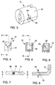
- the locking sleeve 12 shown in FIGS. 3 to 6 comprises in one Wall 24 two formed at an angle to an axis of the locking sleeve 12 Recesses 26, which can be seen as a raceway for one from FIGS. 7 and 8 Serve guide pin 28 which is arranged on the locking pin 10.
- This guide pin 26 is pressed, for example, through a transverse bore in the locking pin 10.
- the recesses or raceways 26 a recessed wall section 30.
- This wall section 30 is in Direction of force of the spring 14 is set back so that the spring 14 engages State of the guide pin 28 in the recessed wall portion 30 through the Spring force.
- the locking pin 10 is available for several locking operations and remains in bore 15 after all settings on the gearbox have been completed Sealing is formed on the locking pin 10 a circumferential groove 32 (Fig. 8) in the for example, an O-ring is arranged as a seal.
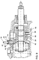
- Fig. 9 shows a second preferred embodiment of an inventive Locking device.
- the same parts are labeled with the same reference numerals, so that for the explanation of which can be referred to the above statements relating to FIGS. 1 to 8.
- switching jaws 34, 36, 38 and 40 can also be seen, each for the reverse gear, for the 1st / 2nd Gear, for the 3rd / 4th Gear and for 5th gear. Further is the sealing ring 41 recognizable.
- This locking device differs essentially from that described above characterized in that the biasing device in the form of a spring 14 in the locking sleeve 12th is arranged between the gear housing 16 and the guide pin 28. It also takes place a bore in the selector shaft 18 a locking plate 42 fixed to the selector shaft 18th connected, which, as can be seen from FIG. 10, has a recess 44; what a a predetermined position of the control shaft 18 with the bore 15 of the transmission housing 16 escapes. Accordingly, the locking pin 10 engages in the locking position Recess 44.
- FIGS. 11 to 13 show the arrangement of a locking device according to the invention on a Switch cover 46.
- the same parts are labeled with the same reference numerals, so that for their Explanation can be made to the above statements on FIGS. 1 to 10.
- a captive device ensures that the locking pin 10 is not can completely fall out of the locking sleeve 12. 1 and 2, this is a Captive cone 46 in a portion of the locking pin 10 in the locking sleeve is led.
- this is an anti-loss device in the form of a ring or a disk 48, which has a larger diameter than an opening 50 of the locking sleeve 12 one end axially in the direction of force of the spring 14.
- the spring 14 is supported on a Side either on the guide pin 28 or on the ring 48.
Abstract
Description
Die Erfindung betrifft eine Arretiervorrichtung für ein Getriebe, insbesondere für ein Kraftfahrzeuggetriebe, mit einem in einem Getriebegehäuse angeordneten Arretierstift, welcher wahlweise gegen eine Kraft einer Vorspannvorrichtung in das Getriebegehäuse hinein in eine Ausnehmung eines beweglichen Getriebeteils einschiebbar ist, gemäß dem Oberbegriff des Anspruchs 1.The invention relates to a locking device for a transmission, in particular for a Motor vehicle transmission, with a locking pin arranged in a transmission housing, which optionally against a force of a pretensioning device in the gear housing can be inserted into a recess of a movable gear part, according to the Preamble of claim 1.
Zum erstmaligen Einstellen eines Getriebes und zum Anschließen einer äußeren Getriebeschaltvorrichtung, wie einen Schalthebel mit entsprechendem Gestänge oder Zügen, müssen die beweglichen Teile des Getriebes bzw. der Schaltvorrichtung in eine vorbestimmte Stellung gebracht und arretiert werden. Hierzu ist es bekannt, an einer vorbestimmten Stelle eines beweglichen Getriebeteiles, wie beispielsweise einer Schalthülse, eine Bohrung auszubilden, welche in einer vorbestimmten Stellung des Getriebes mit einer Bohrung in einem Getriebegehäuse fluchtet. In dieser Stellung wird durch die Bohrung des Getriebegehäuses hindurch und in die Bohrung in der Schalthülse hinein ein Arretierstift gesteckt, welcher ein Schaltmittel im Getriebe in dieser Position arretiert. In dieser Position werden im Getriebe vorbestimmte Einstellungen vorgenommen und beispielsweise äußere Getriebeteile, wie ein Schaltgestänge mit Schalthebel, angeschlossen. Nach Fertigstellung dieser Arbeiten wird der Arretierstift entfernt, wodurch das Getriebeschaltmittel wieder freigegeben wird. Üblicherweise wird als Arretierstift ein herkömmlicher Stift verwendet, der nach den Getriebearbeiten bzw. -einstellungen in der vorbestimmten Stellung aus der Bohrung der Schalthülse herausgezogen werden muß. Um das Getriebe dann abzudichten muß anschließend ein Abdichtbolzen in der Bohrung des Getriebegehäuses montiert werden, dessen Montage oftmals schwierig ist, weil der Ort der Bohrung sehr schwer zugänglich ist. Ein Nachteil solcher Arretiervorrichtung besteht darin, daß sowohl das manuelle Herausziehen aus der Bohrung als auch das Eindrücken des Abdichtbolzens erforderlich sind. Wenn andererseits der Arretierstift versehentlich nicht aus der Bohrung entfernt und/oder der Abdichtbolzen danach nicht in die Bohrung eingeschoben wird, weil dies beispielsweise vergessen wird, ist das ganze Getriebe blockiert und/oder undicht.For the first adjustment of a gearbox and for connecting an external one Gear shift device, such as a gear lever with a corresponding linkage or Trains, the moving parts of the transmission or the switching device must be in one predetermined position brought and locked. For this purpose it is known to use a predetermined location of a movable transmission part, such as one Switching sleeve to form a bore which is in a predetermined position of the Gearbox with a hole in a gearbox housing is aligned. In this position through the hole in the gearbox and into the hole in the shift sleeve inserted a locking pin, which has a switching means in the transmission in this position locked. In this position, predetermined settings are made in the transmission and for example outer gear parts, such as a shift linkage with shift lever, connected. After completing this work, the locking pin is removed, causing the gear shifting means is released again. Usually is used as a locking pin conventional pen used after the gear work or settings in the predetermined position must be pulled out of the bore of the switching sleeve. Around the gearbox must then be sealed with a sealing bolt in the bore of the Gearbox housing are mounted, the assembly of which is often difficult because of the location of the Hole is very difficult to access. A disadvantage of such a locking device is that both the manual pulling out of the hole and the pressing of the Sealing bolt are required. On the other hand, if the locking pin accidentally does not come off removed from the hole and / or the sealing bolt is not inserted into the hole afterwards because, for example, this is forgotten, the entire transmission is blocked and / or leaky.
Es wurden daher auch Arretierstifte verwendet, welche nach dem Entfernen aus der Bohrung der Schalthülse in der Bohrung des Getriebegehäuses festgehalten werden, so daß sie für weitere nachfolgende Fixiervorgänge, wie beispielsweise eine Nacheinstellung des Getriebes, bereit stehen. Hierzu umfassen diese Arretierstifte eine Feder, welche den Arretierstift in der entriegelten Position hält, sowie einen Dichtring, welcher die Bohrung in dem Getriebegehäuse, durch welche sich der Arretierstift erstreckt, abdichtet. Eine Verliersicherung in Form eines Widerhakens, welcher sich an einer Innenwandung des Getriebegehäuses abstützt, verhindert dabei ein vollständiges Herausfallen des Arretierstiftes aus der Bohrung im Getriebegehäuse bzw. bildet einen Anschlag für die Feder. Diese Arretiervorrichtung hat jedoch den Nachteil, daß der Arretierstift lediglich durch Reibkräfte in der Arretierstellung gehalten ist. Dementsprechend darf die Feder in Arretierstellung keine starken entriegelnde Kräfte auf den Arretierstift ausübende, sollte jedoch andererseits in entriegelter Stellung des Arretierstiftes diesen fest in entriegelter Position halten. Diese Bedingungen sind gegenläufig, so daß entweder der Arretierstift durch die zu stark dimensionierte Feder unbeabsichtigt aus der Arretierstellung ausgeschoben wird und so Einstell- und Anschlußarbeiten am Getriebe fehlerhaft ausgeführt werden, oder durch eine zu schwach dimensionierte Feder der Arretierstift unbeabsichtigt in die Arretierstellung rutscht und so das Getriebe blockiert.Locking pins were therefore also used, which after removal from the Bore of the switching sleeve are held in the bore of the gear housing so that them for further subsequent fixing processes, such as a readjustment of the Gear, stand by. For this purpose, these locking pins comprise a spring, which the Locking pin holds in the unlocked position, as well as a sealing ring, which the hole in seals the gear housing through which the locking pin extends. A Loss protection in the form of a barb, which is on an inner wall of the Gearbox supports, prevents the Locking pin from the hole in the gear housing or forms a stop for the Feather. However, this locking device has the disadvantage that the locking pin only by Frictional forces are held in the locking position. Accordingly, the spring in Locking position should not exert strong unlocking forces on the locking pin however, on the other hand, in the unlocked position of the locking pin, it is firmly in the unlocked position Hold position. These conditions are contradictory, so that either the locking pin through the spring, which is too large, is inadvertently pushed out of the locking position and so adjustment and connection work on the transmission are carried out incorrectly, or by a too weakly dimensioned spring of the locking pin unintentionally in the locking position slips, blocking the transmission.
Der vorliegenden Erfindung liegt daher die Aufgabe zugrunde, eine Arretiervorrichtung der obengenannten Art zur Verfügung zu stellen, wobei die obengenannten Nachteile überwunden werden und eine innere Schaltung des Getriebes zum Eistellen und Anschließen einer äußeren Schaltung auf einfache und prozeßsichere Weise fixierbar ist.The present invention is therefore based on the object of a locking device to provide the above type, the above disadvantages be overcome and an internal circuit of the gearbox for ice setting and Connecting an external circuit can be fixed in a simple and reliable manner.
Diese Aufgabe wird erfindungsgemäß durch eine Arretiervorrichtung der o.g. Art mit den in Anspruch 1 gekennzeichneten Merkmalen gelöst. Vorteilhafte Ausgestaltungen der Erfindung sind in den abhängigen Ansprüchen angegeben.This object is achieved by a locking device of the above. Kind of with the in Characteristics characterized claim 1 solved. Advantageous embodiments of the Invention are specified in the dependent claims.
Dazu ist es erfindungsgemäß vorgesehen, daß eine Arretierhülse vorgesehen ist, in welcher der Arretierstift axial geführt ist, wobei die Arretierhülse ein Einrastmittel aufweist, welches mit einem am Arretierstift ausgebildeten Rastmittel derart zusammenwirkt, daß der Arretierstift in einer das Getriebe arretierenden, eingeschobenen Stellung lösbar festgelegt ist.For this purpose, it is provided according to the invention that a locking sleeve is provided, in which the locking pin is guided axially, the locking sleeve having a locking means which cooperates with a locking means formed on the locking pin such that the Locking pin releasably fixed in a retracted, locked position is.
Dies hat den Vorteil, daß eine einfache Verriegelung und Entriegelung des Arretierstiftes erzielt wird, wobei der Arretierstift in Arretierstellung aktiv festgehalten ist und so ein unbeabsichtigtes Ausschieben aus der Arretierstellung heraus wirksam verhindert ist.This has the advantage that simple locking and unlocking of the locking pin is achieved, the locking pin is actively held in the locking position and so unintentional pushing out of the locking position is effectively prevented.
Eine einfache und betriebssichere Arretierung erzielt man dadurch, daß das Einrastmittel wenigstens eine in axialer Richtung verlaufende Ausnehmung in einer Wandung der Arretierhülse und das Rastmittel wenigstens einen sich seitlich am Arretierstift erhebenden und in die Ausnehmung greifenden Führungsstift umfaßt, wobei an einem dem Getriebe zugewandten Ende der Ausnehmung diese in Kraftwirkungsrichtung der Vorspannvorrichtung zurückgesetzt ausgebildet ist. Ferner ergibt sich im Bereich der zurückgesetzten Ausbildung der Ausnehmung eine Haltekante, welche den Führungsstift stabil in dem zurückgesetzten Bereich hält, wobei jedoch der Führungsstift zum Entriegeln und Zurückziehen des Arretierstiftes durch entsprechende Kraftaufwendung und leichtes Drehen des Arretierstiftes um dessen Längsachse einfach über diese Haltekante schiebbar ist.A simple and reliable locking is achieved in that the locking means at least one recess running in the axial direction in a wall of the Locking sleeve and the locking means at least one rising laterally on the locking pin and in the recess engaging guide pin, one on the gear facing end of the recess in the direction of the force Preload device is formed reset. Furthermore, in the area of reset formation of the recess a retaining edge which the guide pin Stably holds in the recessed area, but with the guide pin to unlock and retraction of the locking pin by appropriate force and light Rotation of the locking pin about its longitudinal axis can be easily pushed over this retaining edge is.
Eine prozeßsichere Führung des Arretierstiftes mittels des Führungsstiftes in der Ausnehmung der Wandung der Arretierhülse mit sicher festlegendem Eingriff der Führungsstiftes in den zurückversetzten Abschnitt der Ausnehmung bei gleichzeitig einfacher Lösbarkeit dieser Festlegung des Arretierstiftes in einer Arretierstellung erzielt man dadurch, daß die wenigstens eine Ausnehmung unter einem vorbestimmten Winkel zu einer Achse der Arretierhülse in deren Wandung ausgebildet ist.A reliable guidance of the locking pin by means of the guide pin in the Recess of the wall of the locking sleeve with securely fixing engagement of the Guide pin in the recessed section of the recess at the same time simple detachability of this fixing of the locking pin in a locking position is achieved in that the at least one recess at a predetermined angle to a Axis of the locking sleeve is formed in the wall.
Eine direkte und exakte Arretierung des Getriebes in einer vorbestimmten Position erzielt man dadurch, daß das bewegliche Getriebeteil eine Schaltstange ist.A direct and exact locking of the gearbox is achieved in a predetermined position one in that the movable gear part is a shift rod.
Eine einfache Bedienbarkeit des Einschiebens und Ausschiebens des Arretierstiftes erzielt man dadurch, daß der Arretierstift L-förmig ausgebildet ist. A simple operability of pushing in and pushing out the locking pin is achieved one in that the locking pin is L-shaped.
Einen sicheren Sitz und eine exakte vorbestimmte Ausrichtung des Arretierstiftes erzielt man dadurch, daß die Arretierhülse wenigstens teilweise in einer Bohrung im Getriebegehäuse angeordnet ist.A secure fit and an exact predetermined alignment of the locking pin is achieved in that the locking sleeve at least partially in a bore in the gear housing is arranged.
In einer bevorzugten Ausführungsform ist die Vorspannvorrichtung eine Schraubenfeder.In a preferred embodiment, the biasing device is a coil spring.
Eine Abdichtung der Durchstoßstelle des Arretierstiftes durch das Gehäuse erzielt man dadurch, daß in einem in der Arretierhülse angeordneten Abschnitt des Arretierstiftes eine umlaufende Nut mit einem Dichtungsring vorgesehen ist.A sealing of the piercing point of the locking pin by the housing is achieved characterized in that in a arranged in the locking sleeve portion of the locking pin circumferential groove is provided with a sealing ring.
Einen einfachen Aufbau mit symmetrisch auf den Arretierstift wirkenden Führungskräften erzielt man dadurch, daß der Führungsstift in einer Durchgangsbohrung im Arretierstift eingepreßt ist und sich beidseits des Arretierstiftes erhebt.A simple construction with executives acting symmetrically on the locking pin is achieved in that the guide pin in a through hole in the locking pin is pressed in and rises on both sides of the locking pin.
Entsprechende Abstützstellen für die Vorspannvorrichtung ohne zusätzliche Maßnahmen oder Elemente erzielt man dadurch, daß die Vorspannvorrichtung innerhalb der Arretierhülse zwischen dem Gehäuse und dem Rastmittel des Arretierstiftes angeordnet ist. Dadurch stützt sich die Vorspannvorrichtung an einem Ende am Getriebegehäuse und an einem entsprechend gegenüberliegenden Ende am Rastmittel des Arretierstiftes ab.Appropriate support points for the pretensioning device without additional measures or elements can be achieved by the pretensioning device inside the locking sleeve is arranged between the housing and the locking means of the locking pin. Thereby the pretensioner is supported at one end on the gear housing and at one correspondingly opposite end from the locking means of the locking pin.
Zum Verhindern eines unbeabsichtigten Herausfallens des Arretierstiftes aus der Arretierhülse ist am Arretierstift eine Verliersicherung ausgebildet. Diese umfaßt zweckmäßigerweise eine innerhalb der Arretierhülse und um den Arretierstift herum angeordnete Scheibe, deren Durchmesser größer ist als eine Öffnung der Arretierhülse, oder einen Verliersicherungskonus in einem Abschnitt des Arretierstiftes umfaßt, welcher in der Arretierhülse geführt ist.To prevent the locking pin from accidentally falling out of the Locking sleeve is formed on the locking pin captive. This includes expediently one inside the locking sleeve and around the locking pin arranged disc, the diameter of which is larger than an opening of the locking sleeve, or includes a captive cone in a portion of the locking pin which is in the locking sleeve is guided.
Weitere Merkmale, Vorteile und vorteilhafte Ausgestaltungen der Erfindung ergeben sich aus den abhängigen Ansprüchen, sowie aus der nachstehenden Beschreibung der Erfindung anhand der beigefügten Zeichnungen. Diese zeigen in
- Fig. 1
- eine Schnittansicht einer ersten bevorzugten Ausführungsform einer erfindungsgemäßen Arretiervorrichtung in Arretierstellung,
- Fig. 2
- in gelöster Stellung,
- Fig. 3
- eine Arretierhülse in perspektivischer Ansicht,
- Fig. 4
- in einer Seitenansicht,
- Fig. 5
- in einer Schnittansicht entlang Linie A-A von Fig. 4,
- Fig. 6
- in einer Schnittansicht entlang Linie B-B von Fig. 5,
- Fig. 7
- einen Arretierstift in Seitenansicht,
- Fig. 8
- in einer Schnittansicht entlang Linie A-A von Fig. 7,
- Fig. 9
- eine Schnittansicht einer zweiten bevorzugten Ausführungsform einer erfindungsgemäßen Arretiervorrichtung,
- Fig. 10
- eine Aufsicht eines Sperrbleches der zweiten bevorzugten Ausführungsform von Fig. 9 in Richtung Pfeil R von Fig. 9,
- Fig. 11
- eine Aufsicht eines Schaltdeckels eines Getriebes,
- Fig. 12
- eine Schnittansicht entlang Linie A-A von Fig. 11 und
- Fig. 13
- eine Schnittansicht entlang Linie E-E von Fig. 11.
- Fig. 1
- 2 shows a sectional view of a first preferred embodiment of a locking device according to the invention in the locking position,
- Fig. 2
- in the released position,
- Fig. 3
- a locking sleeve in perspective view,
- Fig. 4
- in a side view,
- Fig. 5
- in a sectional view along line AA of FIG. 4,
- Fig. 6
- in a sectional view along line BB of FIG. 5,
- Fig. 7
- a locking pin in side view,
- Fig. 8
- in a sectional view along line AA of FIG. 7,
- Fig. 9
- 2 shows a sectional view of a second preferred embodiment of a locking device according to the invention,
- Fig. 10
- 9 shows a top view of a locking plate of the second preferred embodiment from FIG. 9 in the direction of arrow R from FIG. 9,
- Fig. 11
- a top view of a shift cover of a transmission,
- Fig. 12
- a sectional view taken along line AA of Fig. 11 and
- Fig. 13
- 10 shows a sectional view along line EE of FIG. 11.
Die in Fig. 1 und 2 dargestellte erste bevorzugte Ausführungsform einer erfindungsgemäßen
Arretiervorrichtung umfaßt einen Arretierstift 10, welcher in einer Arretierhülse 12 geführt
und von einer Feder 14 vorgespannt ist. Die Arretierhülse 12 ist teilweise in einer Bohrung
15 eines Getriebegehäuses 16 angeordnet. In dem Getriebegehäuse 16 befindet sich eine
Schaltwelle 18 mit einem Schaltfinger 20, welcher durch entsprechende axiale Translations- und
Rotationsbewegungen der Schaltwelle 18 in nicht dargestellte Schaltmaule von nicht
dargestellten Schaltstangen bzw. -schienen zum Ein- bzw. Ausrücken eines entsprechenden
Ganges des Getriebes greift.The first preferred embodiment shown in FIGS. 1 and 2 of an inventive
Locking device comprises a locking
In der Schaltwelle 18 ist eine Bohrung 22 ausgebildet, welche in einer vorbestimmten
Stellung der Schaltwelle 18 mit der Bohrung 15 im Getriebegehäuse 16 fluchtet. In dieser
Stellung der Schaltwelle 18 ist der Arretierstift 10 derart in das Getriebe einschiebbar, daß er
in die Bohrung 22 der Schaltwelle 18 greift und so diese bzgl. des Getriebegehäuses 16
festlegt, d.h. jede Bewegung der Schaltwelle 18 verhindert, wie in Fig. 1 dargestellt. In dieser
Stellung ist das Getriebe somit arretiert, so daß diese Stellung des Arretierstiftes 10
nachfolgend als Arretierstellung bezeichnet wird. Zieht man den Arretierstift 10 jedoch
zurück, dann gibt dieser die Schaltwelle 18 und damit das Getriebe wieder frei. Diese
Stellung des Arretierstiftes 10 ist in Fig. 2 dargestellt und wird nachfolgend als
Entriegelstellung bezeichnet.In the
Die Festlegung des Arretierstiftes in Arretierstellung wird nachfolgend unter Bezugnahme auf
die Fig. 3 bis 8 erläutert. Die in Fig. 3 bis 6 dargestellte Arretierhülse 12 umfaßt in einer
Wandung 24 zwei unter einem Winkel zu einer Achse der Arretierhülse 12 ausgebildete
Ausnehmungen 26, welche als Laufbahn für einen aus Fig. 7 und 8 ersichtlichen
Führungsstift 28 dienen, welcher am Arretierstift 10 angeordnet ist. Dieser Führungsstift 26
ist beispielsweise durch eine Querbohrung im Arretierstift 10 eingepreßt. Beim Einschieben
des Arretierstiftes 10 in Richtung Arretierstellung wird somit der L-förmig ausgebildete
Arretierstift 10 in der Arretierhülse 12 über den in den Ausnehmungen 26 laufenden
Führungsstift 28 geführt und wie ein Hebel gedreht. Sobald der Führungsstift 28 an einem
Ende, d.h. in Arretierstellung, angelangt ist, weisen die Ausnehmungen bzw. Laufbahnen 26
einen zurückgesetzten Wandabschnitt 30 auf. Dieser Wandabschnitt 30 ist in
Kraftwirkungsrichtung der Feder 14 zurückversetzt, so daß die Feder 14 den eingerasteten
Zustand des Führungsstiftes 28 in dem zurückgesetzten Wandabschnitt 30 durch die
Federkraft festlegt. Zum Entriegeln muß der Führungsstift 28 aus dem zurückgesetzten
Wandabschnitt 30 heraus über eine Haltekante 32 hinweg durch entsprechende
Kraftaufwendung am Hebel des Arretierstiftes 10 verschoben werden. Sobald sich der
Führungsstift 28 außerhalb des zurückgesetzten Wandabschnittes 30 befindet sorgt bereits
allein die Federkraft für eine weitere axiale Verschiebung des Arretierstiftes 10 in
Entriegelstellung. The definition of the locking pin in the locking position is described below with reference to
3 to 8 explained. The locking
Auf diese Weise ist steht der Arretierstift 10 für mehrere Arretieroperationen zur Verfügung
und verbleibt auch nach Beendigung aller Einstellungen am Getriebe in der Bohrung 15. Zur
Abdichtung ist am Arretierstift 10 eine umlaufende Nut 32 ausgebildet (Fig. 8), in der
beispielsweise ein O-Ring als Dichtung angeordnet ist.In this way, the locking
Fig. 9 zeigt eine zweite bevorzugte Ausführungsform einer erfindungsgemäßen
Arretiervorrichtung. Gleiche Teile sind mit gleichen Bezugsziffern bezeichnet, so daß für
deren Erläuterung auf obige Ausführungen zu Fig. 1 bis 8 verwiesen werden kann. Aus der
Darstellung von Fig. 9 sind zusätzlich Schaltmaule 34, 36, 38 und 40 erkennbar, jeweils für
den Rückwärtsgang, für den 1./2. Gang, für den 3./4. Gang und für den 5. Gang. Ferner ist
der Dichtring 41 erkennbar.Fig. 9 shows a second preferred embodiment of an inventive
Locking device. The same parts are labeled with the same reference numerals, so that for
the explanation of which can be referred to the above statements relating to FIGS. 1 to 8. From the
9, switching
Diese Arretiervorrichtung unterscheidet sich von der zuvor beschriebenen im wesentlichen
dadurch, daß die Vorspannvorrichtung in Form einer Feder 14 in der Arretierhülse 12
zwischen dem Getriebegehäuse 16 und dem Führungsstift 28 angeordnet ist. Ferner ist statt
einer Bohrung in der Schaltwelle 18 ein Sperrblech 42 fest mit der Schaltwelle 18
verbunden, welches, wie aus Fig. 10 ersichtlich, eine Ausnehmung 44 Aufweist; welche in
einer vorbestimmten Stellung der Schaltwelle 18 mit der Bohrung 15 des Getriebegehäuses
16 fluchtet. Dementsprechend greift in Arretierstellung der Arretierstift 10 in diese
Ausnehmung 44.This locking device differs essentially from that described above
characterized in that the biasing device in the form of a
Fig. 11 bis 13 zeigen die Anordnung einer erfindungsgemäßen Arretiervorrichtung an einem
Schaltdeckel 46. Gleiche Teile sind mit gleichen Bezugsziffern bezeichnet, so daß für deren
Erläuterung auf obige Ausführungen zu Fig. 1 bis 10 verwiesen werden kann.11 to 13 show the arrangement of a locking device according to the invention on a
In allen Ausführungsformen sorgt eine Verliersicherung dafür, daß der Arretierstift 10 nicht
aus der Arretierhülse 12 vollständig herausfallen kann. In Fig. 1 und 2 ist dies ein
Verliersicherungskonus 46 in einem Abschnitt des Arretierstiftes 10, der in der Arretierhülse
geführt ist. In Fig. 9 ist dies eine Verliersicherung in Form eines Ringes bzw. einer Scheibe
48, welche einen größeren Durchmesser hat als eine Öffnung 50 der Arretierhülse 12 an
einem Ende axial in Kraftwirkungsrichtung der Feder 14. Die Feder 14 stützt sich an einer
Seite entweder am Führungsstift 28 oder am Ring 48 ab. In all embodiments, a captive device ensures that the locking
- 1010th
- ArretierstiftLocking pin
- 1212th
- ArretierhülseLocking sleeve
- 1414
- Federfeather
- 1515
- Bohrung in GetriebegehäuseHole in the gearbox
- 1616
- GetriebegehäuseGear housing
- 1818th
- SchaltwelleSelector shaft
- 2020th
- SchaltfingerShift finger
- 2222
- Bohrung in SchaltwelleBore in selector shaft
- 2424th
- Wandung der ArretierhülseWall of the locking sleeve
- 2626
- AusnehmungenRecesses
- 2828
- FührungsstiftGuide pin
- 3030th
- zurückgesetzter Wandabschnittrecessed wall section
- 3232
- umlaufende Nut am Arretierstiftcircumferential groove on the locking pin
- 3434
- SchaltmaulShift mouthpiece
- 3636
- SchaltmaulShift mouthpiece
- 3838
- SchaltmaulShift mouthpiece
- 4040
- SchaltmaulShift mouthpiece
- 4141
- DichtringSealing ring
- 4242
- SperrblechPawl
- 4444
- AusnehmungRecess
- 4646
- VerliersicherungskonusCaptive cone
- 4848
- Ringring
Claims (13)
dadurch gekennzeichnet, daß
eine Arretierhülse (12) vorgesehen ist, in welcher der Arretierstift (10) axial geführt ist, wobei die Arretierhülse (12) ein Einrastmittel (26) aufweist, welches mit einem am Arretierstift (10) ausgebildeten Rastmittel (28) derart zusammenwirkt, daß der Arretierstift (10) in einer das Getriebe arretierenden, eingeschobenen Stellung lösbar festgelegt ist.Locking device for a gearbox, in particular for a motor vehicle gearbox, with a locking pin (10) arranged in a gearbox housing (16), which optionally against a force of a pretensioning device (14) into the gearbox housing (16) into a recess (22) of a movable gearbox part (18) can be inserted,
characterized in that
a locking sleeve (12) is provided, in which the locking pin (10) is guided axially, the locking sleeve (12) having a latching means (26) which cooperates with a locking means (28) formed on the locking pin (28) such that the Locking pin (10) is releasably fixed in a retracted, locked position.
dadurch gekennzeichnet, daß
das Einrastmittel wenigstens eine in axialer Richtung verlaufende Ausnehmung (26) in einer Wandung (24) der Arretierhülse (12) und das Rastmittel wenigstens einen sich seitlich am Arretierstift erhebenden und in die Ausnehmung greifenden Führungsstift (28) umfaßt, wobei an einem dem Getriebe zugewandten Ende der Ausnehmung (26) diese in Kraftwirkungsrichtung der Vorspannvorrichtung (14) zurückgesetzt ausgebildet ist.Locking device according to claim 1,
characterized in that
the latching means comprises at least one axially extending recess (26) in a wall (24) of the locking sleeve (12) and the latching means comprises at least one guide pin (28) rising laterally on the locking pin and engaging in the recess, one facing the gear End of the recess (26) is formed recessed in the direction of the biasing device (14).
dadurch gekennzeichnet, daß
die wenigstens eine Ausnehmung (26) unter einem vorbestimmten Winkel zu einer Achse der Arretierhülse (12) in deren Wandung (24) ausgebildet ist. Locking device according to claim 2,
characterized in that
the at least one recess (26) is formed at a predetermined angle to an axis of the locking sleeve (12) in the wall (24) thereof.
dadurch gekennzeichnet, daß
das bewegliche Getriebeteil eine Schaltstange (18) ist.Locking device according to one of the preceding claims,
characterized in that
the movable gear part is a shift rod (18).
dadurch gekennzeichnet, daß
der Arretierstift (10) L-förmig ausgebildet ist.Locking device according to one of the preceding claims,
characterized in that
the locking pin (10) is L-shaped.
dadurch gekennzeichnet, daß
die Arretierhülse (12) wenigstens teilweise in einer Bohrung (15) im Getriebegehäuse (16) angeordnet ist.Locking device according to one of the preceding claims,
characterized in that
the locking sleeve (12) is at least partially arranged in a bore (15) in the gear housing (16).
dadurch gekennzeichnet, daß
die Vorspannvorrichtung eine Schraubenfeder (14) ist.Locking device according to one of the preceding claims,
characterized in that
the biasing device is a coil spring (14).
dadurch gekennzeichnet, daß
in einem in der Arretierhülse (12) angeordneten Abschnitt des Arretierstiftes (10) eine umlaufende Nut (32) mit einem Dichtungsring (41) vorgesehen ist.Locking device according to one of the preceding claims,
characterized in that
A circumferential groove (32) with a sealing ring (41) is provided in a section of the locking pin (10) arranged in the locking sleeve (12).
dadurch gekennzeichnet, daß
der Führungsstift (28) in einer Durchgangsbohrung im Arretierstift (10) eingepreßt ist und sich beidseits des Arretierstiftes (10) erhebt.Locking device according to one of the preceding claims,
characterized in that
the guide pin (28) is pressed into a through hole in the locking pin (10) and rises on both sides of the locking pin (10).
dadurch gekennzeichnet, daß
die Vorspannvorrichtung (14) innerhalb der Arretierhülse (12) zwischen dem Getriebegehäuse (16) und dem Rastmittel (28) des Arretierstiftes (10) angeordnet ist.Locking device according to one of the preceding claims,
characterized in that
the pretensioning device (14) is arranged within the locking sleeve (12) between the gear housing (16) and the latching means (28) of the locking pin (10).
dadurch gekennzeichnet, daß
am Arretierstift (10) eine Verliersicherung (46;48) ausgebildet ist.Locking device according to one of the preceding claims,
characterized in that
A locking device (46; 48) is formed on the locking pin (10).
dadurch gekennzeichnet, daß
die Verliersicherung eine innerhalb der Arretierhülse (12) und um den Arretierstift (10) herum angeordnete Scheibe (48) umfaßt, deren Durchmesser größer ist als eine Öffnung (50) der Arretierhülse (12).Locking device according to claim 11,
characterized in that
the captive device comprises a disk (48) which is arranged inside the locking sleeve (12) and around the locking pin (10) and has a diameter larger than an opening (50) of the locking sleeve (12).
dadurch gekennzeichnet, daß
die Verliersicherung einen Verliersicherungskonus (46) in einem Abschnitt des Arretierstiftes (10) umfaßt, welcher in der Arretierhülse (12) geführt ist.Locking device according to claim 11,
characterized in that
the captive device comprises a captive cone (46) in a section of the locking pin (10) which is guided in the locking sleeve (12).
Applications Claiming Priority (2)
| Application Number | Priority Date | Filing Date | Title |
|---|---|---|---|
| DE19809424 | 1998-03-05 | ||
| DE19809424A DE19809424B4 (en) | 1998-03-05 | 1998-03-05 | Locking device for a transmission |
Publications (3)
| Publication Number | Publication Date |
|---|---|
| EP0940606A2 true EP0940606A2 (en) | 1999-09-08 |
| EP0940606A3 EP0940606A3 (en) | 2000-12-13 |
| EP0940606B1 EP0940606B1 (en) | 2003-05-07 |
Family
ID=7859803
Family Applications (1)
| Application Number | Title | Priority Date | Filing Date |
|---|---|---|---|
| EP99101647A Expired - Lifetime EP0940606B1 (en) | 1998-03-05 | 1999-02-05 | Locking device for a transmission |
Country Status (3)
| Country | Link |
|---|---|
| EP (1) | EP0940606B1 (en) |
| DE (2) | DE19809424B4 (en) |
| ES (1) | ES2198795T3 (en) |
Cited By (14)
| Publication number | Priority date | Publication date | Assignee | Title |
|---|---|---|---|---|
| FR2885981A1 (en) * | 2005-05-20 | 2006-11-24 | Peugeot Citroen Automobiles Sa | Provisional lock for motor vehicle gearbox selector and gear shift lever comprises movable locking key engaged with facing slots in lever and clutch housing |
| FR2902171A1 (en) * | 2006-06-09 | 2007-12-14 | Renault Sas | Inner control units locking device for motor vehicle, has selection lever presenting orifice superposable at notch formed at case such that introduction of axle across orifice and notch immobilizes lever in reference position |
| FR2904081A1 (en) * | 2006-07-18 | 2008-01-25 | Renault Sas | Gearbox drive shaft locking device for motor vehicle, has rod comprising concave end that is supported on drive shaft of gearbox, when rod is in neutral position, for applying locking torque to drive shaft |
| WO2008132015A1 (en) | 2007-04-28 | 2008-11-06 | Schaeffler Kg | Locking device for securing the position of a shifting element |
| WO2009000595A1 (en) | 2007-06-23 | 2008-12-31 | Schaeffler Kg | Component of a vehicle transmission and device having a locking pin for locking a transmission part of the component |
| WO2009027174A1 (en) * | 2007-08-28 | 2009-03-05 | Schaeffler Kg | Locking mechanism for a selector shaft in a transmission |
| WO2009027175A1 (en) * | 2007-08-28 | 2009-03-05 | Schaeffler Kg | Locking mechanism for a selector shaft in a transmission |
| WO2009153119A2 (en) * | 2008-06-19 | 2009-12-23 | Schaeffler Kg | Mounting and transport safety arrangement for a shift mechanism of a transmission |
| EP2138743A1 (en) * | 2008-06-25 | 2009-12-30 | ZF Friedrichshafen AG | Switching device with lock |
| FR2965323A1 (en) * | 2010-09-28 | 2012-03-30 | Peugeot Citroen Automobiles Sa | Device for temporary blocking speed disengagement, engagement and selection lever of gearbox of vehicle i.e. car, has atmospheric pressure channel arranged in guiding body and in displacement direction of rod |
| CN101660606B (en) * | 2009-09-21 | 2012-10-10 | 重庆大学 | Combined locking mechanism for shifting between master and slave boxes in mechanical transmission |
| CN104514879A (en) * | 2013-09-26 | 2015-04-15 | 上海汽车集团股份有限公司 | Automobile transmission gear locking device, transmission and automobile |
| CN104520614A (en) * | 2012-06-14 | 2015-04-15 | 舍弗勒技术有限两合公司 | Locking device for a gear unit, in particular for a motor vehicle gearbox |
| WO2019080968A1 (en) * | 2017-10-25 | 2019-05-02 | Schaeffler Technologies AG & Co. KG | Shift device and a method for installing a shift device |
Families Citing this family (9)
| Publication number | Priority date | Publication date | Assignee | Title |
|---|---|---|---|---|
| DE102007011034A1 (en) | 2007-03-07 | 2008-09-11 | Schaeffler Kg | Device for locking and unlocking movable gear-part e.g. for central switch-shaft, has gear-part axially gripped and locked in one position by retaining member |
| DE102009027561B4 (en) * | 2009-07-09 | 2022-04-28 | Zf Friedrichshafen Ag | Switching or selection actuator for a switching device of an automated manual transmission |
| DE102012213177B4 (en) * | 2012-07-26 | 2019-12-19 | Schaeffler Technologies AG & Co. KG | Shift dome for a manual transmission of a motor vehicle |
| DE102012223218B4 (en) | 2012-12-14 | 2015-02-05 | Schaeffler Technologies Gmbh & Co. Kg | Locking device for a transmission, in particular for a motor vehicle transmission |
| DE102016201720A1 (en) * | 2016-02-04 | 2017-08-24 | Zf Friedrichshafen Ag | Arrangement for securing a force-loaded shift rail |
| CN106438998B (en) * | 2016-05-28 | 2019-05-21 | 重庆万虎机电有限责任公司 | A kind of mini-tiller, gearbox and the driving device of clutch yoke |
| DE102016219918A1 (en) * | 2016-10-13 | 2017-10-12 | Schaeffler Technologies AG & Co. KG | Transport and / or assembly security |
| US20220196059A1 (en) * | 2019-04-04 | 2022-06-23 | Suprajit Engineering Limited | An assembly for securing a ferrule to a gear-box using a spring-loaded lock pin |
| CN110259942B (en) * | 2019-05-31 | 2021-07-23 | 陕西法士特齿轮有限责任公司 | Parking device for automatic transmission |
Family Cites Families (4)
| Publication number | Priority date | Publication date | Assignee | Title |
|---|---|---|---|---|
| DE4341644B4 (en) * | 1992-12-18 | 2006-07-27 | Volkswagen Ag | gear selector |
| DE4441138C2 (en) * | 1994-11-18 | 1996-09-19 | Juergen Decker | Fixing pin for a gear actuator |
| DE19540039A1 (en) * | 1995-10-27 | 1997-04-30 | Schaeffler Waelzlager Kg | Shift lock |
| DE19805924A1 (en) * | 1998-02-13 | 1999-08-26 | Kochendoerfer & Kiep Stanz Und | transmission |
-
1998
- 1998-03-05 DE DE19809424A patent/DE19809424B4/en not_active Expired - Fee Related
-
1999
- 1999-02-05 DE DE59905389T patent/DE59905389D1/en not_active Expired - Lifetime
- 1999-02-05 EP EP99101647A patent/EP0940606B1/en not_active Expired - Lifetime
- 1999-02-05 ES ES99101647T patent/ES2198795T3/en not_active Expired - Lifetime
Non-Patent Citations (1)
| Title |
|---|
| None |
Cited By (18)
| Publication number | Priority date | Publication date | Assignee | Title |
|---|---|---|---|---|
| FR2885981A1 (en) * | 2005-05-20 | 2006-11-24 | Peugeot Citroen Automobiles Sa | Provisional lock for motor vehicle gearbox selector and gear shift lever comprises movable locking key engaged with facing slots in lever and clutch housing |
| FR2902171A1 (en) * | 2006-06-09 | 2007-12-14 | Renault Sas | Inner control units locking device for motor vehicle, has selection lever presenting orifice superposable at notch formed at case such that introduction of axle across orifice and notch immobilizes lever in reference position |
| FR2904081A1 (en) * | 2006-07-18 | 2008-01-25 | Renault Sas | Gearbox drive shaft locking device for motor vehicle, has rod comprising concave end that is supported on drive shaft of gearbox, when rod is in neutral position, for applying locking torque to drive shaft |
| CN101668966B (en) * | 2007-04-28 | 2013-04-24 | 谢夫勒科技两合公司 | Locking device for securing the position of a shifting element |
| WO2008132015A1 (en) | 2007-04-28 | 2008-11-06 | Schaeffler Kg | Locking device for securing the position of a shifting element |
| WO2009000595A1 (en) | 2007-06-23 | 2008-12-31 | Schaeffler Kg | Component of a vehicle transmission and device having a locking pin for locking a transmission part of the component |
| CN101711319B (en) * | 2007-06-23 | 2013-12-18 | 谢夫勒科技两合公司 | Component of vehicle transmission and device having locking pin for locking transmission part of component |
| WO2009027175A1 (en) * | 2007-08-28 | 2009-03-05 | Schaeffler Kg | Locking mechanism for a selector shaft in a transmission |
| WO2009027174A1 (en) * | 2007-08-28 | 2009-03-05 | Schaeffler Kg | Locking mechanism for a selector shaft in a transmission |
| WO2009153119A2 (en) * | 2008-06-19 | 2009-12-23 | Schaeffler Kg | Mounting and transport safety arrangement for a shift mechanism of a transmission |
| WO2009153119A3 (en) * | 2008-06-19 | 2010-02-18 | Schaeffler Kg | Mounting and transport safety arrangement for a shift mechanism of a transmission |
| EP2138743A1 (en) * | 2008-06-25 | 2009-12-30 | ZF Friedrichshafen AG | Switching device with lock |
| CN101660606B (en) * | 2009-09-21 | 2012-10-10 | 重庆大学 | Combined locking mechanism for shifting between master and slave boxes in mechanical transmission |
| FR2965323A1 (en) * | 2010-09-28 | 2012-03-30 | Peugeot Citroen Automobiles Sa | Device for temporary blocking speed disengagement, engagement and selection lever of gearbox of vehicle i.e. car, has atmospheric pressure channel arranged in guiding body and in displacement direction of rod |
| CN104520614A (en) * | 2012-06-14 | 2015-04-15 | 舍弗勒技术有限两合公司 | Locking device for a gear unit, in particular for a motor vehicle gearbox |
| CN104520614B (en) * | 2012-06-14 | 2017-12-19 | 舍弗勒技术股份两合公司 | Stop device for speed changer |
| CN104514879A (en) * | 2013-09-26 | 2015-04-15 | 上海汽车集团股份有限公司 | Automobile transmission gear locking device, transmission and automobile |
| WO2019080968A1 (en) * | 2017-10-25 | 2019-05-02 | Schaeffler Technologies AG & Co. KG | Shift device and a method for installing a shift device |
Also Published As
| Publication number | Publication date |
|---|---|
| EP0940606B1 (en) | 2003-05-07 |
| DE19809424B4 (en) | 2008-10-02 |
| ES2198795T3 (en) | 2004-02-01 |
| EP0940606A3 (en) | 2000-12-13 |
| DE59905389D1 (en) | 2003-06-12 |
| DE19809424A1 (en) | 1999-09-09 |
Similar Documents
| Publication | Publication Date | Title |
|---|---|---|
| EP0940606B1 (en) | Locking device for a transmission | |
| EP1805427B1 (en) | Traction-pressure rod | |
| DE4336620C2 (en) | Power tool with a clamping device that can only be operated when the engine is switched off | |
| EP0582804B1 (en) | Shifting mechanism for a transmission | |
| DE102009053966A1 (en) | Arrangement and method for connecting an accessory to an operating table | |
| DE102009001535A1 (en) | Assembly, method of use of this assembly and tool for applying the method | |
| EP1612455B1 (en) | Gearshift/selector lever of a vehicle transmission | |
| DE19706866A1 (en) | Device for automatic, gradual rope length compensation of a Bowden cable system | |
| EP1809441B1 (en) | Tensioning or gripping device in particular a linear or centering gripper | |
| EP0975904A1 (en) | Gear with central control shaft | |
| DE102020111757A1 (en) | Parking lock with a synchronizer | |
| EP1379797A1 (en) | Single-shaft switching device | |
| DE102014202886A1 (en) | Switching arrangement for a transmission | |
| EP0111790B1 (en) | Door check | |
| EP0438611B1 (en) | Rotation-preventing locking device for a rotating component, especially for a cutting tool | |
| EP0848789B1 (en) | Compensating element for a pulling and pressing rod | |
| DE102016124920A1 (en) | Sliding wheel for a manual transmission arrangement | |
| EP1746313A1 (en) | Shift lock mechanism for gearbox | |
| DE102004018244B4 (en) | Manual shift lever for a vehicle transmission | |
| DE10045266A1 (en) | Operating unit for multistage gear box for motor vehicles has selector shaft axially moveable in gear housing via shift lever, and with radially offset driver elements | |
| DE4341644A1 (en) | Gear selector for motor vehicle transmission | |
| DE102006043165B4 (en) | Lever device for a hand brake valve of a brake system | |
| DE10219356B4 (en) | Gearbox for manual transmission | |
| DE607043C (en) | Switching device for gear change transmissions of motor vehicles | |
| EP4012200B1 (en) | Spring-loaded detent bolt |
Legal Events
| Date | Code | Title | Description |
|---|---|---|---|
| PUAI | Public reference made under article 153(3) epc to a published international application that has entered the european phase |
Free format text: ORIGINAL CODE: 0009012 |
|
| AK | Designated contracting states |
Kind code of ref document: A2 Designated state(s): DE ES FR GB IT SE |
|
| AX | Request for extension of the european patent |
Free format text: AL;LT;LV;MK;RO;SI |
|
| PUAL | Search report despatched |
Free format text: ORIGINAL CODE: 0009013 |
|
| AK | Designated contracting states |
Kind code of ref document: A3 Designated state(s): AT BE CH CY DE DK ES FI FR GB GR IE IT LI LU MC NL PT SE |
|
| AX | Request for extension of the european patent |
Free format text: AL;LT;LV;MK;RO;SI |
|
| 17P | Request for examination filed |
Effective date: 20010613 |
|
| AKX | Designation fees paid |
Free format text: DE ES FR GB IT SE |
|
| 17Q | First examination report despatched |
Effective date: 20020411 |
|
| GRAH | Despatch of communication of intention to grant a patent |
Free format text: ORIGINAL CODE: EPIDOS IGRA |
|
| RIC1 | Information provided on ipc code assigned before grant |
Free format text: 7F 16H 63/34 A |
|
| RTI1 | Title (correction) |
Free format text: LOCKING DEVICE FOR A TRANSMISSION |
|
| GRAH | Despatch of communication of intention to grant a patent |
Free format text: ORIGINAL CODE: EPIDOS IGRA |
|
| GRAA | (expected) grant |
Free format text: ORIGINAL CODE: 0009210 |
|
| AK | Designated contracting states |
Designated state(s): DE ES FR GB IT SE |
|
| PG25 | Lapsed in a contracting state [announced via postgrant information from national office to epo] |
Ref country code: IT Free format text: LAPSE BECAUSE OF FAILURE TO SUBMIT A TRANSLATION OF THE DESCRIPTION OR TO PAY THE FEE WITHIN THE PRESCRIBED TIME-LIMIT;WARNING: LAPSES OF ITALIAN PATENTS WITH EFFECTIVE DATE BEFORE 2007 MAY HAVE OCCURRED AT ANY TIME BEFORE 2007. THE CORRECT EFFECTIVE DATE MAY BE DIFFERENT FROM THE ONE RECORDED. Effective date: 20030507 Ref country code: GB Free format text: LAPSE BECAUSE OF FAILURE TO SUBMIT A TRANSLATION OF THE DESCRIPTION OR TO PAY THE FEE WITHIN THE PRESCRIBED TIME-LIMIT Effective date: 20030507 |
|
| REG | Reference to a national code |
Ref country code: GB Ref legal event code: FG4D Free format text: NOT ENGLISH |
|
| REF | Corresponds to: |
Ref document number: 59905389 Country of ref document: DE Date of ref document: 20030612 Kind code of ref document: P |
|
| PG25 | Lapsed in a contracting state [announced via postgrant information from national office to epo] |
Ref country code: SE Free format text: LAPSE BECAUSE OF FAILURE TO SUBMIT A TRANSLATION OF THE DESCRIPTION OR TO PAY THE FEE WITHIN THE PRESCRIBED TIME-LIMIT Effective date: 20030807 |
|
| GBV | Gb: ep patent (uk) treated as always having been void in accordance with gb section 77(7)/1977 [no translation filed] |
Effective date: 20030507 |
|
| ET | Fr: translation filed | ||
| REG | Reference to a national code |
Ref country code: ES Ref legal event code: FG2A Ref document number: 2198795 Country of ref document: ES Kind code of ref document: T3 |
|
| PLBE | No opposition filed within time limit |
Free format text: ORIGINAL CODE: 0009261 |
|
| STAA | Information on the status of an ep patent application or granted ep patent |
Free format text: STATUS: NO OPPOSITION FILED WITHIN TIME LIMIT |
|
| 26N | No opposition filed |
Effective date: 20040210 |
|
| PGFP | Annual fee paid to national office [announced via postgrant information from national office to epo] |
Ref country code: ES Payment date: 20140321 Year of fee payment: 16 |
|
| REG | Reference to a national code |
Ref country code: FR Ref legal event code: PLFP Year of fee payment: 17 |
|
| PGFP | Annual fee paid to national office [announced via postgrant information from national office to epo] |
Ref country code: DE Payment date: 20150228 Year of fee payment: 17 |
|
| PGFP | Annual fee paid to national office [announced via postgrant information from national office to epo] |
Ref country code: FR Payment date: 20150227 Year of fee payment: 17 |
|
| REG | Reference to a national code |
Ref country code: ES Ref legal event code: FD2A Effective date: 20160329 |
|
| PG25 | Lapsed in a contracting state [announced via postgrant information from national office to epo] |
Ref country code: ES Free format text: LAPSE BECAUSE OF NON-PAYMENT OF DUE FEES Effective date: 20150206 |
|
| REG | Reference to a national code |
Ref country code: DE Ref legal event code: R119 Ref document number: 59905389 Country of ref document: DE |
|
| REG | Reference to a national code |
Ref country code: FR Ref legal event code: ST Effective date: 20161028 |
|
| PG25 | Lapsed in a contracting state [announced via postgrant information from national office to epo] |
Ref country code: FR Free format text: LAPSE BECAUSE OF NON-PAYMENT OF DUE FEES Effective date: 20160229 Ref country code: DE Free format text: LAPSE BECAUSE OF NON-PAYMENT OF DUE FEES Effective date: 20160901 |