EP0940568A1 - Verfahren zur Erfassung des Druckverlaufes in einem Brennkraftmaschinenzylinder - Google Patents
Verfahren zur Erfassung des Druckverlaufes in einem Brennkraftmaschinenzylinder Download PDFInfo
- Publication number
- EP0940568A1 EP0940568A1 EP99103321A EP99103321A EP0940568A1 EP 0940568 A1 EP0940568 A1 EP 0940568A1 EP 99103321 A EP99103321 A EP 99103321A EP 99103321 A EP99103321 A EP 99103321A EP 0940568 A1 EP0940568 A1 EP 0940568A1
- Authority
- EP
- European Patent Office
- Prior art keywords
- engine
- internal pressure
- progress
- jωm
- cylinder
- Prior art date
- Legal status (The legal status is an assumption and is not a legal conclusion. Google has not performed a legal analysis and makes no representation as to the accuracy of the status listed.)
- Granted
Links
- 238000000034 method Methods 0.000 title claims abstract description 32
- 238000002485 combustion reaction Methods 0.000 title claims abstract description 27
- 230000009466 transformation Effects 0.000 claims description 11
- 230000002596 correlated effect Effects 0.000 claims description 2
- 238000005070 sampling Methods 0.000 claims 4
- 238000005316 response function Methods 0.000 description 6
- 238000004519 manufacturing process Methods 0.000 description 4
- 238000005259 measurement Methods 0.000 description 4
- 238000010586 diagram Methods 0.000 description 3
- 230000000694 effects Effects 0.000 description 3
- 238000004364 calculation method Methods 0.000 description 2
- 238000012986 modification Methods 0.000 description 2
- 230000004048 modification Effects 0.000 description 2
- 230000015572 biosynthetic process Effects 0.000 description 1
- 239000000110 cooling liquid Substances 0.000 description 1
- 230000000875 corresponding effect Effects 0.000 description 1
- 238000013213 extrapolation Methods 0.000 description 1
- 239000000446 fuel Substances 0.000 description 1
- 239000007789 gas Substances 0.000 description 1
- 230000007774 longterm Effects 0.000 description 1
- 230000000717 retained effect Effects 0.000 description 1
- 238000003786 synthesis reaction Methods 0.000 description 1
- 230000008646 thermal stress Effects 0.000 description 1
- 238000000844 transformation Methods 0.000 description 1
Images

Classifications
-
- G—PHYSICS
- G01—MEASURING; TESTING
- G01M—TESTING STATIC OR DYNAMIC BALANCE OF MACHINES OR STRUCTURES; TESTING OF STRUCTURES OR APPARATUS, NOT OTHERWISE PROVIDED FOR
- G01M15/00—Testing of engines
- G01M15/04—Testing internal-combustion engines
- G01M15/042—Testing internal-combustion engines by monitoring a single specific parameter not covered by groups G01M15/06 - G01M15/12
- G01M15/046—Testing internal-combustion engines by monitoring a single specific parameter not covered by groups G01M15/06 - G01M15/12 by monitoring revolutions
-
- F—MECHANICAL ENGINEERING; LIGHTING; HEATING; WEAPONS; BLASTING
- F02—COMBUSTION ENGINES; HOT-GAS OR COMBUSTION-PRODUCT ENGINE PLANTS
- F02B—INTERNAL-COMBUSTION PISTON ENGINES; COMBUSTION ENGINES IN GENERAL
- F02B77/00—Component parts, details or accessories, not otherwise provided for
- F02B77/08—Safety, indicating, or supervising devices
-
- F—MECHANICAL ENGINEERING; LIGHTING; HEATING; WEAPONS; BLASTING
- F02—COMBUSTION ENGINES; HOT-GAS OR COMBUSTION-PRODUCT ENGINE PLANTS
- F02D—CONTROLLING COMBUSTION ENGINES
- F02D35/00—Controlling engines, dependent on conditions exterior or interior to engines, not otherwise provided for
- F02D35/02—Controlling engines, dependent on conditions exterior or interior to engines, not otherwise provided for on interior conditions
- F02D35/023—Controlling engines, dependent on conditions exterior or interior to engines, not otherwise provided for on interior conditions by determining the cylinder pressure
- F02D35/024—Controlling engines, dependent on conditions exterior or interior to engines, not otherwise provided for on interior conditions by determining the cylinder pressure using an estimation
-
- F—MECHANICAL ENGINEERING; LIGHTING; HEATING; WEAPONS; BLASTING
- F02—COMBUSTION ENGINES; HOT-GAS OR COMBUSTION-PRODUCT ENGINE PLANTS
- F02D—CONTROLLING COMBUSTION ENGINES
- F02D41/00—Electrical control of supply of combustible mixture or its constituents
- F02D41/02—Circuit arrangements for generating control signals
- F02D41/14—Introducing closed-loop corrections
- F02D41/1401—Introducing closed-loop corrections characterised by the control or regulation method
- F02D2041/1433—Introducing closed-loop corrections characterised by the control or regulation method using a model or simulation of the system
-
- F—MECHANICAL ENGINEERING; LIGHTING; HEATING; WEAPONS; BLASTING
- F02—COMBUSTION ENGINES; HOT-GAS OR COMBUSTION-PRODUCT ENGINE PLANTS
- F02D—CONTROLLING COMBUSTION ENGINES
- F02D41/00—Electrical control of supply of combustible mixture or its constituents
- F02D41/24—Electrical control of supply of combustible mixture or its constituents characterised by the use of digital means
- F02D41/26—Electrical control of supply of combustible mixture or its constituents characterised by the use of digital means using computer, e.g. microprocessor
- F02D41/28—Interface circuits
- F02D2041/286—Interface circuits comprising means for signal processing
- F02D2041/288—Interface circuits comprising means for signal processing for performing a transformation into the frequency domain, e.g. Fourier transformation
-
- F—MECHANICAL ENGINEERING; LIGHTING; HEATING; WEAPONS; BLASTING
- F02—COMBUSTION ENGINES; HOT-GAS OR COMBUSTION-PRODUCT ENGINE PLANTS
- F02D—CONTROLLING COMBUSTION ENGINES
- F02D2200/00—Input parameters for engine control
- F02D2200/02—Input parameters for engine control the parameters being related to the engine
- F02D2200/10—Parameters related to the engine output, e.g. engine torque or engine speed
- F02D2200/1015—Engines misfires
Definitions
- the present invention relates to a method for determining the progress of internal pressure in a cylinder of an internal combustion engine (1).
- a pressure sensor is located inside the combustion chamber relating to the cylinder.
- the pressure sensor effects a direct measurement of internal pressure in that it outputs an electrical signal representative of the internal pressure.
- the pressure sensors of known type although allowing a direct time evolution of the internal pressure to the cylinder to be obtained have the disadvantage of being extremely costly, and owing to the hostile conditions of the environment in which they operate, are subject to mechanical and thermal stresses of such a nature as to prejudice their suitable operation in the long term.
- the method is mainly based on the correlation between internal pressure to the cylinder and the engine block vibrations.
- the method provides for the use of a piezoelectric accelerometer mounted on the engine block to correspond with the cylinder to generate an electric signal output representative of the engine block vibrations, and the use of a processing system allowing the extrapolation of the pattern of the internal signal from the pattern of the electrical output signal from the accelerometer.
- the scope of the present invention is to provide a method for determining the progress of internal pressure to the cylinder of an internal combustion engine, which will be free from the aforementioned disadvantages, or will allow simple and economical determination of the progress of internal pressure without the need for modifications to the engine block and without the aid of external sensors on the actual engine block.
- a method is provided to determine the progress of internal pressure to the cylinder of an internal combustion engine, the said method comprising the stages of recording the progress of the physical size of the said engine, and the determination of the progress of internal pressure to the cylinder in accordance with the said physical size; the method being characterised in that the progress of internal pressure of the said physical size is correlated with the pattern of immediate angular speed of the engine shaft.
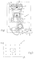
- a « four-stroke » engine of known type is indicated as a whole by reference 1, comprising a support base 2, and a plurality of cylinders 3 (of which only one is illustrated) carried by the base 2 and defining respective combustion chambers 4 to match the relevant upper ends.
- a respective piston 5 is fitted, which is connected to the engine shaft 6 in a known manner by way of a respective con-rod 7, and axially movable inside the cylinder 3 itself between an upper position (known as top dead centre) and a lower position (known as the bottom dead centre).
- the engine 1 comprises an intake manifold 8 connected to the cylinders 3 to supply a flow of combustible matter (air) in the cylinders 3, a fuel supply arrangement 9 in the cylinders 3, an ignition arrangement 12 to strike the combustion within the chambers 4, and an exhaust manifold 13 connected with the cylinders 3 to direct the burned gases in the outlet.
- an intake manifold 8 connected to the cylinders 3 to supply a flow of combustible matter (air) in the cylinders 3, a fuel supply arrangement 9 in the cylinders 3, an ignition arrangement 12 to strike the combustion within the chambers 4, and an exhaust manifold 13 connected with the cylinders 3 to direct the burned gases in the outlet.
- the engine is controlled by a central control 14 which cooperates with a plurality of internal sensors on the engine block to receive information signals at the inlet, representative of the physical dimensions of the engine 1, for example the position of the butterfly valve, the temperature of the cooling liquid and so on.
- the centralised unit 14 is connected to a speed sensor 15 for the shaft 6 which generates on outlet a speed signal v(t) representative of the immediate angular speed of the shaft 6, and to a pressure sensor 16 placed along the intake manifold duct 8 to generate a pressure signal Pc(t) representative of the pressure in the manifold 8.
- the central control 14 comprises a processing unit 17, which receives as input the immediate angular speed signal v(t) of the shaft 6, and is designed to generate for each cylinder 3 of the engine 1, a respective output signal P(t) representative of the progress of the internal pressure to the cylinder 3.
- the processing unit 17 is designed to define for each combustion cycle of the engine 1, the progress in time of the internal pressure of each cylinder 3 in relation to a time interval which comprises the moment when the associated piston 5 of the cylinder 3 is at top dead centre in the ignition phase.
- the unit 17 allows the definition of the progress of internal pressure towards the chamber 4 in a time interval comprising the ignition phase, as soon as the progress has been noted of the angular speed of the shaft 6 of the engine within the same time interval.
- a block 40 is entered in which is determined the existing operating point of the engine 1 in accordance with an assembly of operational parameters for the engine 1.
- the existing operating point is characterised by two operational parameters: the rate of engine rpm (revolutions per minute) and average pressure Pcm in intake manifold 8.
- the actual operating point is characterised on the basis of the values of the average Pcm pressure and rate of engine rpm relative to the combustion cycle before the existing cycle; the values of average Pcm pressure and rate of engine rpm relative to the preceding combustion cycle to the existing cycle are available in that they have been calculated by way of the Pc(t) signals, and respectively the v(t) signal for the preceding combustion cycle.
- a block 50 is entered wherein are sampled a specific number N of values of the v(t) signal of immediate angular speed of the shaft 6; hereinafter indicated as v 0 , v 1 ,...,v N-1 , the said sampled values, relate to a time interval comprising the moment at which the piston 5 is located in the top dead centre at the ignition stage.
- the interval I represents the time interval in which the angular position ⁇ of the shaft 6 (figure 1) is comprised within an angular interval I ⁇ (figure 4) of an extent equal to 180° and centred in the angular position in which the piston 5 comes into the bottom dead centre point during the ignition stage.
- Block 60 goes on to block 70 in which is calculated as will be seen later, a frequential response function H(j ⁇ m) relating to the actual operating point of the engine 1 and expressing the link between the progress of the angular speed v(t) signal and the internal pressure signal p(t) of the cylinder 3 within the scope of angular frequencies.
- a frequential response function H(j ⁇ m) relating to the actual operating point of the engine 1 and expressing the link between the progress of the angular speed v(t) signal and the internal pressure signal p(t) of the cylinder 3 within the scope of angular frequencies.
- each engine operation point is associated with a specific frequential response function H(j ⁇ m).
- Block 80 goes on to block 90 in which the anti-transformation operation according to Fourier of the P(j ⁇ m) transformation is carried out to obtain the evolution of the P(t) signal internal pressure to cylinder 3 in the I time interval.
- the anti-transformation operation is carried out according to the known expression of wherein P 0 , P 1 ,....,P N-1 , indicate the reconstructed values for internal pressure in the cylinder 3 at the moments when the v 0 ,v 1 ,....,v N-1 values are sampled within the I time interval.
- the processing unit 17 provides on output the progress of the internal pressure P(t) to cylinder 3 relatively to the I time interval, or during the combustion.
- the relationship of (3) is thus the key to the reconstruction of the internal pressure signal P(t) from the angular speed output signal v(t) from the sensor 15.
- the relationship (3) is based on the existence of an experimentally proved linear correlation, between the progress of the immediate internal pressure to a cylinder 3 in the interval I, or in a corresponding angular position interval IQ assumed by the engine shaft 6 centred about the position in which the piston 5 is at top dead centre. It has been found experimentally that to reconstruct with reasonable approximation the signal P(t), it is possible to take into consideration only a certain number of harmonics, for instance the first seven harmonics; this provides the expression (4) which allows the progress of internal pressure to become
- Calculation of the function (H(j ⁇ m)), effected in block 70, is made on the basis of the knowledge of a plurality of reference frequential response (H R (j ⁇ m), each of which relates to a specific reference operating point R of the engine 1, and is stored within the processing unit 17.
- the (H(j ⁇ m)) function relating to the actual operating point (indicated as K on the (rpm,Pcm) plane is calculated while taking into consideration a sub-assembly S of points R. That sub-assembly S comprises reference points R closest to the actual operating point K.
- the (H(j ⁇ m)) function relating to point K is calculated while effecting an average assessment of (HR(jWm) functions forming part of sub-assembly S according to the expression wherein D R is the weight associated with point R, and is a function of the distance between point R and point K on the (rpm,Pcm) plane.
- reference points R are arranged in such a manner as to form a grid G, and sub-assembly S comprises the four points R surrounding the actual operating point K.
- Reference functions H R (j ⁇ m) of reference points R, stored in the processing unit 17, each expresses the link between the V(j ⁇ m) Fourier transformation of angular speed signals v(t) of engine shaft 6 and the Fourier transformation P(j ⁇ m) of the internal pressure signals P(t) to cylinder 3 when the engine 1 is at the operating point R, that is to say H R (j ⁇ m) V j ⁇ m P j ⁇ m
- Such H R (j ⁇ m) frequential response functions are acquired following reference to a sample engine having the same geometrical and structural characteristics as engine 1 (for instance con-rod length, crankshaft length, piston surface area, etc..).
- a sample engine having the same geometrical and structural characteristics as engine 1 (for instance con-rod length, crankshaft length, piston surface area, etc..).
- a pressure sensor internally mounted in the combustion chamber of the cylinder to generate directly on output the P(t) internal pressure signals to the cylinder.
- H R (j ⁇ m) All the frequential response functions H R (j ⁇ m) are defined with reference to the sample motor. Such H R (j ⁇ m) functions are stored in the processing unit 17 of the engine 1 to allow return to the time progress of the internal pressure to cylinder 3 without having to install a pressure sensor inside the combustion chamber 4.
- the method according to this invention allows the reconstruction of the progress of the internal pressure at the cylinder with an optimum level of approximation.
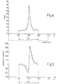
- graphically representing the progress of internal pressure at the cylinder 3 according to the angular position of the engine shaft in the angular interval I ⁇ of the engine shaft the following may be observed: the progress of internal pressure, reconstructed from the processing unit 17 and illustrated as a continuous line in figure 4, does not differ significantly from the progress of internal pressure measured directly with a pressure sensor fitted inside the cylinder (progress illustrated in broken lines). This shows that the processing unit 17 is able to provide a time evolution of the internal pressure to the cylinder 3 very close to that achieved by direct measurement.
- Figure 5 shows as a continuous line the reconstruction of the progress of the torque transmitted to the shaft 6 in the aforesaid angular interval I ⁇ ; it can be seen how once again the progress does not differ significantly from the progress which would be obtained by direct measurement of the transmitted torque (see the broken line).
Landscapes
- Engineering & Computer Science (AREA)
- Chemical & Material Sciences (AREA)
- Combustion & Propulsion (AREA)
- Mechanical Engineering (AREA)
- General Engineering & Computer Science (AREA)
- Physics & Mathematics (AREA)
- General Physics & Mathematics (AREA)
- Combined Controls Of Internal Combustion Engines (AREA)
- Output Control And Ontrol Of Special Type Engine (AREA)
Applications Claiming Priority (2)
| Application Number | Priority Date | Filing Date | Title |
|---|---|---|---|
| ITBO980100 | 1998-02-20 | ||
| IT98BO000100A IT1299857B1 (it) | 1998-02-20 | 1998-02-20 | Metodo per la determinazione dell'andamento della pressione interna ad un cilindro di un motore endotermico. |
Publications (2)
| Publication Number | Publication Date |
|---|---|
| EP0940568A1 true EP0940568A1 (de) | 1999-09-08 |
| EP0940568B1 EP0940568B1 (de) | 2002-10-30 |
Family
ID=11342922
Family Applications (1)
| Application Number | Title | Priority Date | Filing Date |
|---|---|---|---|
| EP99103321A Expired - Lifetime EP0940568B1 (de) | 1998-02-20 | 1999-02-19 | Verfahren zur Erfassung des Druckverlaufes in einem Brennkraftmaschinenzylinder |
Country Status (6)
| Country | Link |
|---|---|
| US (1) | US6188952B1 (de) |
| EP (1) | EP0940568B1 (de) |
| BR (1) | BR9900499A (de) |
| DE (1) | DE69903679T2 (de) |
| ES (1) | ES2186263T3 (de) |
| IT (1) | IT1299857B1 (de) |
Cited By (2)
| Publication number | Priority date | Publication date | Assignee | Title |
|---|---|---|---|---|
| EP0985919B1 (de) * | 1998-09-10 | 2005-03-23 | MAGNETI MARELLI POWERTRAIN S.p.A. | Verfahren zur Bestimmung der Drehmomententwicklung einer Brennkraftmaschine |
| FR2923539A1 (fr) * | 2008-04-30 | 2009-05-15 | Continental Automotive France | Estimateur de signal d'acceleration |
Families Citing this family (10)
| Publication number | Priority date | Publication date | Assignee | Title |
|---|---|---|---|---|
| DE19845232A1 (de) * | 1998-10-01 | 2000-04-06 | Bosch Gmbh Robert | Verfahren und Vorrichtung zur Bewertung von Verbrennungsvorgängen an einer Brennkraftmaschine |
| DE10108876A1 (de) * | 2000-03-13 | 2001-09-20 | Luk Lamellen & Kupplungsbau | Drehmomentübertragungssystem |
| US6668812B2 (en) * | 2001-01-08 | 2003-12-30 | General Motors Corporation | Individual cylinder controller for three-cylinder engine |
| DE10343146A1 (de) * | 2003-09-18 | 2005-04-14 | Daimlerchrysler Ag | Verfahren und Vorrichtung zur Erfassung des Zylinderdrucks und/oder fehlerhafter Zündungen und/oder des Klopfens bei Brennkraftmaschinen mittels Sensoren |
| FR2891012B1 (fr) * | 2005-09-20 | 2011-02-11 | Inst Francais Du Petrole | Methode d'estimation du regime instantane produit par chacun des cylindres d'un moteur a combustion interne |
| FR2898411B1 (fr) * | 2006-03-08 | 2008-05-16 | Inst Francais Du Petrole | Methode d'estimation en temps reel de parametres de combustion moteur a partir de signaux vibratoires |
| GB2442751A (en) * | 2006-10-13 | 2008-04-16 | Denso Corp | Engine Parameter Signal Estimation |
| US7878048B2 (en) * | 2008-06-16 | 2011-02-01 | GM Global Technology Operations LLC | Fuel system injection timing diagnostics by analyzing cylinder pressure signal |
| US9410867B2 (en) * | 2014-12-09 | 2016-08-09 | Caterpillar Inc. | Laser system for measuring internal cylinder pressure |
| DE102019207252B4 (de) * | 2018-11-14 | 2024-09-12 | Vitesco Technologies GmbH | Erfassung von zylinderindividuellen Brennverlaufsparameterwerten für einen Verbrennungsmotor |
Citations (7)
| Publication number | Priority date | Publication date | Assignee | Title |
|---|---|---|---|---|
| US4843870A (en) * | 1988-07-25 | 1989-07-04 | Purdue Research Foundation | Cylinder-by-cylinder engine pressure and pressure torque waveform determination utilizing crankshaft speed fluctuations |
| EP0501531A1 (de) * | 1989-06-14 | 1992-09-02 | FIAT AUTO S.p.A. | Verfahren und System zur Überwachung des Betriebverhaltens einer Brennkraftmaschine, insbesondere einer Brennkraftmaschine mit elektronischer Einspritzung |
| US5200899A (en) * | 1990-04-20 | 1993-04-06 | Regents Of The University Of Michigan | Method and system for detecting the misfire of an internal combustion engine utilizing angular velocity fluctuations |
| US5394330A (en) * | 1992-11-12 | 1995-02-28 | Texas Instruments Incorporated | System and method for monitoring an operating state of an engine |
| EP0670482A2 (de) * | 1994-03-04 | 1995-09-06 | Mercedes-Benz Ag | Verfahren zur Bestimmung des durch Gaskräfte auf die Kurbelwelle einer Brennkraftmaschine übertragenen Drehmoments |
| US5631411A (en) * | 1992-04-30 | 1997-05-20 | Avl Gesellschaft Fuer Verbrennungskraftmaschinen Und Messtechnik M.B.H. Prof. Dr. Dr. H.C. Hans List | Method and apparatus for engine monitoring |
| JPH09236514A (ja) * | 1996-02-29 | 1997-09-09 | Mitsubishi Heavy Ind Ltd | エンジンの運転状態診断装置 |
Family Cites Families (1)
| Publication number | Priority date | Publication date | Assignee | Title |
|---|---|---|---|---|
| DE4006273A1 (de) * | 1990-02-28 | 1991-09-26 | Forsch Kraftfahrwesen Und Fahr | Verfahren und vorrichtung zur ermittlung des verlaufs des innendrucks eines zylinders einer kolbenmaschine |
-
1998
- 1998-02-20 IT IT98BO000100A patent/IT1299857B1/it active IP Right Grant
-
1999
- 1999-02-19 BR BR9900499-2A patent/BR9900499A/pt not_active IP Right Cessation
- 1999-02-19 DE DE69903679T patent/DE69903679T2/de not_active Expired - Lifetime
- 1999-02-19 ES ES99103321T patent/ES2186263T3/es not_active Expired - Lifetime
- 1999-02-19 US US09/253,557 patent/US6188952B1/en not_active Expired - Lifetime
- 1999-02-19 EP EP99103321A patent/EP0940568B1/de not_active Expired - Lifetime
Patent Citations (7)
| Publication number | Priority date | Publication date | Assignee | Title |
|---|---|---|---|---|
| US4843870A (en) * | 1988-07-25 | 1989-07-04 | Purdue Research Foundation | Cylinder-by-cylinder engine pressure and pressure torque waveform determination utilizing crankshaft speed fluctuations |
| EP0501531A1 (de) * | 1989-06-14 | 1992-09-02 | FIAT AUTO S.p.A. | Verfahren und System zur Überwachung des Betriebverhaltens einer Brennkraftmaschine, insbesondere einer Brennkraftmaschine mit elektronischer Einspritzung |
| US5200899A (en) * | 1990-04-20 | 1993-04-06 | Regents Of The University Of Michigan | Method and system for detecting the misfire of an internal combustion engine utilizing angular velocity fluctuations |
| US5631411A (en) * | 1992-04-30 | 1997-05-20 | Avl Gesellschaft Fuer Verbrennungskraftmaschinen Und Messtechnik M.B.H. Prof. Dr. Dr. H.C. Hans List | Method and apparatus for engine monitoring |
| US5394330A (en) * | 1992-11-12 | 1995-02-28 | Texas Instruments Incorporated | System and method for monitoring an operating state of an engine |
| EP0670482A2 (de) * | 1994-03-04 | 1995-09-06 | Mercedes-Benz Ag | Verfahren zur Bestimmung des durch Gaskräfte auf die Kurbelwelle einer Brennkraftmaschine übertragenen Drehmoments |
| JPH09236514A (ja) * | 1996-02-29 | 1997-09-09 | Mitsubishi Heavy Ind Ltd | エンジンの運転状態診断装置 |
Non-Patent Citations (1)
| Title |
|---|
| PATENT ABSTRACTS OF JAPAN vol. 098, no. 001 30 January 1998 (1998-01-30) * |
Cited By (2)
| Publication number | Priority date | Publication date | Assignee | Title |
|---|---|---|---|---|
| EP0985919B1 (de) * | 1998-09-10 | 2005-03-23 | MAGNETI MARELLI POWERTRAIN S.p.A. | Verfahren zur Bestimmung der Drehmomententwicklung einer Brennkraftmaschine |
| FR2923539A1 (fr) * | 2008-04-30 | 2009-05-15 | Continental Automotive France | Estimateur de signal d'acceleration |
Also Published As
| Publication number | Publication date |
|---|---|
| ITBO980100A1 (it) | 1999-08-20 |
| EP0940568B1 (de) | 2002-10-30 |
| BR9900499A (pt) | 2000-03-08 |
| DE69903679D1 (de) | 2002-12-05 |
| ITBO980100A0 (it) | 1998-02-20 |
| ES2186263T3 (es) | 2003-05-01 |
| IT1299857B1 (it) | 2000-04-04 |
| DE69903679T2 (de) | 2003-06-12 |
| US6188952B1 (en) | 2001-02-13 |
Similar Documents
| Publication | Publication Date | Title |
|---|---|---|
| EP0940568B1 (de) | Verfahren zur Erfassung des Druckverlaufes in einem Brennkraftmaschinenzylinder | |
| Liu et al. | An experimental study on engine dynamics model based in-cylinder pressure estimation | |
| CN101725419B (zh) | 控制内燃发动机的麦克风信号法 | |
| JP3084060B2 (ja) | ピストンエンジンのシリンダーにおける内圧の変動を測定する方法および装置 | |
| US8256278B2 (en) | Engine misfire detection systems and methods using discrete fourier transform approximation | |
| US7292926B2 (en) | Method and device for estimation of combustion chamber pressure | |
| CN102454503B (zh) | 用于估计发动机操作参数的方法和装置 | |
| Eriksson et al. | Cylinder state estimation from measured cylinder pressure traces-a survey | |
| Amirante et al. | Towards the development of the in-cylinder pressure measurement based on the strain gauge technique for internal combustion engines | |
| Zhixiong et al. | On-line indicated torque estimation for internal combustion engines using discrete observer | |
| Shiao et al. | Misfire detection and cylinder pressure reconstruction for SI engines | |
| JP4410417B2 (ja) | 内燃機関における燃焼過程の評価方法および装置 | |
| Macián et al. | A comparison of different methods for fuel delivery unevenness detection in Diesel engines | |
| CN100578003C (zh) | 计算发动机的做功量的装置和方法 | |
| EP0985919B1 (de) | Verfahren zur Bestimmung der Drehmomententwicklung einer Brennkraftmaschine | |
| Fehrenbach | Model-based combustion pressure computation through crankshaft angular acceleration analysis | |
| Brand et al. | Estimation of the instantaneous in-cylinder pressure for control purposes using crankshaft angular velocity | |
| FR2507250A1 (fr) | Dispositif pour mesurer la position angulaire du vilebrequin d'un moteur a combustion interne | |
| CN101813033A (zh) | 用于控制内燃发动机中燃烧调相的方法和设备 | |
| WO2008080861A1 (fr) | Procede d'estimation du couple d'un moteur a combustion interne | |
| Goering | Engine heat release via spread sheet | |
| Andersson et al. | A system inversion approach on a crankshaft of an internal combustion engine | |
| KR102119872B1 (ko) | 단기통 4행정 엔진의 실화 진단 방법 및 시스템 | |
| RU96109098A (ru) | Стенд обкатки и диагностики двигателей внутреннего сгорания | |
| Chaumerliac et al. | Control-oriented spark engine model |
Legal Events
| Date | Code | Title | Description |
|---|---|---|---|
| PUAI | Public reference made under article 153(3) epc to a published international application that has entered the european phase |
Free format text: ORIGINAL CODE: 0009012 |
|
| AK | Designated contracting states |
Kind code of ref document: A1 Designated state(s): DE ES FR GB SE |
|
| AX | Request for extension of the european patent |
Free format text: AL;LT;LV;MK;RO;SI |
|
| 17P | Request for examination filed |
Effective date: 19991018 |
|
| AKX | Designation fees paid |
Free format text: DE ES FR GB SE |
|
| 17Q | First examination report despatched |
Effective date: 20010517 |
|
| GRAG | Despatch of communication of intention to grant |
Free format text: ORIGINAL CODE: EPIDOS AGRA |
|
| GRAG | Despatch of communication of intention to grant |
Free format text: ORIGINAL CODE: EPIDOS AGRA |
|
| GRAH | Despatch of communication of intention to grant a patent |
Free format text: ORIGINAL CODE: EPIDOS IGRA |
|
| RAP1 | Party data changed (applicant data changed or rights of an application transferred) |
Owner name: MAGNETI MARELLI POWERTRAIN S.P.A. |
|
| GRAH | Despatch of communication of intention to grant a patent |
Free format text: ORIGINAL CODE: EPIDOS IGRA |
|
| GRAA | (expected) grant |
Free format text: ORIGINAL CODE: 0009210 |
|
| AK | Designated contracting states |
Kind code of ref document: B1 Designated state(s): DE ES FR GB SE |
|
| REG | Reference to a national code |
Ref country code: GB Ref legal event code: FG4D |
|
| REF | Corresponds to: |
Ref document number: 69903679 Country of ref document: DE Date of ref document: 20021205 |
|
| REG | Reference to a national code |
Ref country code: ES Ref legal event code: FG2A Ref document number: 2186263 Country of ref document: ES Kind code of ref document: T3 |
|
| ET | Fr: translation filed | ||
| PLBE | No opposition filed within time limit |
Free format text: ORIGINAL CODE: 0009261 |
|
| STAA | Information on the status of an ep patent application or granted ep patent |
Free format text: STATUS: NO OPPOSITION FILED WITHIN TIME LIMIT |
|
| 26N | No opposition filed |
Effective date: 20030731 |
|
| PGFP | Annual fee paid to national office [announced via postgrant information from national office to epo] |
Ref country code: ES Payment date: 20090227 Year of fee payment: 11 |
|
| PGFP | Annual fee paid to national office [announced via postgrant information from national office to epo] |
Ref country code: GB Payment date: 20090216 Year of fee payment: 11 |
|
| PGFP | Annual fee paid to national office [announced via postgrant information from national office to epo] |
Ref country code: SE Payment date: 20090213 Year of fee payment: 11 |
|
| EUG | Se: european patent has lapsed | ||
| GBPC | Gb: european patent ceased through non-payment of renewal fee |
Effective date: 20100219 |
|
| REG | Reference to a national code |
Ref country code: ES Ref legal event code: FD2A Effective date: 20110309 |
|
| PG25 | Lapsed in a contracting state [announced via postgrant information from national office to epo] |
Ref country code: GB Free format text: LAPSE BECAUSE OF NON-PAYMENT OF DUE FEES Effective date: 20100219 |
|
| PG25 | Lapsed in a contracting state [announced via postgrant information from national office to epo] |
Ref country code: ES Free format text: LAPSE BECAUSE OF NON-PAYMENT OF DUE FEES Effective date: 20110308 |
|
| PG25 | Lapsed in a contracting state [announced via postgrant information from national office to epo] |
Ref country code: ES Free format text: LAPSE BECAUSE OF NON-PAYMENT OF DUE FEES Effective date: 20100220 |
|
| PG25 | Lapsed in a contracting state [announced via postgrant information from national office to epo] |
Ref country code: SE Free format text: LAPSE BECAUSE OF NON-PAYMENT OF DUE FEES Effective date: 20100220 |
|
| REG | Reference to a national code |
Ref country code: FR Ref legal event code: PLFP Year of fee payment: 17 |
|
| PGFP | Annual fee paid to national office [announced via postgrant information from national office to epo] |
Ref country code: DE Payment date: 20150122 Year of fee payment: 17 |
|
| PGFP | Annual fee paid to national office [announced via postgrant information from national office to epo] |
Ref country code: FR Payment date: 20150220 Year of fee payment: 17 |
|
| REG | Reference to a national code |
Ref country code: DE Ref legal event code: R119 Ref document number: 69903679 Country of ref document: DE |
|
| REG | Reference to a national code |
Ref country code: FR Ref legal event code: ST Effective date: 20161028 |
|
| PG25 | Lapsed in a contracting state [announced via postgrant information from national office to epo] |
Ref country code: FR Free format text: LAPSE BECAUSE OF NON-PAYMENT OF DUE FEES Effective date: 20160229 Ref country code: DE Free format text: LAPSE BECAUSE OF NON-PAYMENT OF DUE FEES Effective date: 20160901 |