EP0940516A1 - Panneau de construction - Google Patents
Panneau de construction Download PDFInfo
- Publication number
- EP0940516A1 EP0940516A1 EP98200702A EP98200702A EP0940516A1 EP 0940516 A1 EP0940516 A1 EP 0940516A1 EP 98200702 A EP98200702 A EP 98200702A EP 98200702 A EP98200702 A EP 98200702A EP 0940516 A1 EP0940516 A1 EP 0940516A1
- Authority
- EP
- European Patent Office
- Prior art keywords
- panel
- lattice
- fastening
- concrete
- core
- Prior art date
- Legal status (The legal status is an assumption and is not a legal conclusion. Google has not performed a legal analysis and makes no representation as to the accuracy of the status listed.)
- Withdrawn
Links
Images


Classifications
-
- E—FIXED CONSTRUCTIONS
- E04—BUILDING
- E04C—STRUCTURAL ELEMENTS; BUILDING MATERIALS
- E04C2/00—Building elements of relatively thin form for the construction of parts of buildings, e.g. sheet materials, slabs, or panels
- E04C2/02—Building elements of relatively thin form for the construction of parts of buildings, e.g. sheet materials, slabs, or panels characterised by specified materials
- E04C2/26—Building elements of relatively thin form for the construction of parts of buildings, e.g. sheet materials, slabs, or panels characterised by specified materials composed of materials covered by two or more of groups E04C2/04, E04C2/08, E04C2/10 or of materials covered by one of these groups with a material not specified in one of the groups
- E04C2/284—Building elements of relatively thin form for the construction of parts of buildings, e.g. sheet materials, slabs, or panels characterised by specified materials composed of materials covered by two or more of groups E04C2/04, E04C2/08, E04C2/10 or of materials covered by one of these groups with a material not specified in one of the groups at least one of the materials being insulating
- E04C2/288—Building elements of relatively thin form for the construction of parts of buildings, e.g. sheet materials, slabs, or panels characterised by specified materials composed of materials covered by two or more of groups E04C2/04, E04C2/08, E04C2/10 or of materials covered by one of these groups with a material not specified in one of the groups at least one of the materials being insulating composed of insulating material and concrete, stone or stone-like material
- E04C2/2885—Building elements of relatively thin form for the construction of parts of buildings, e.g. sheet materials, slabs, or panels characterised by specified materials composed of materials covered by two or more of groups E04C2/04, E04C2/08, E04C2/10 or of materials covered by one of these groups with a material not specified in one of the groups at least one of the materials being insulating composed of insulating material and concrete, stone or stone-like material with the insulating material being completely surrounded by, or embedded in, a stone-like material, e.g. the insulating material being discontinuous
-
- E—FIXED CONSTRUCTIONS
- E04—BUILDING
- E04C—STRUCTURAL ELEMENTS; BUILDING MATERIALS
- E04C2/00—Building elements of relatively thin form for the construction of parts of buildings, e.g. sheet materials, slabs, or panels
- E04C2/02—Building elements of relatively thin form for the construction of parts of buildings, e.g. sheet materials, slabs, or panels characterised by specified materials
- E04C2/04—Building elements of relatively thin form for the construction of parts of buildings, e.g. sheet materials, slabs, or panels characterised by specified materials of concrete or other stone-like material; of asbestos cement; of cement and other mineral fibres
- E04C2/049—Building elements of relatively thin form for the construction of parts of buildings, e.g. sheet materials, slabs, or panels characterised by specified materials of concrete or other stone-like material; of asbestos cement; of cement and other mineral fibres completely or partially of insulating material, e.g. cellular concrete or foamed plaster
Definitions
- the invention relates to an insulated structural panel suitable for use in a prefabricated building system.
- pre-insulated structural panels are known and these are establishing themselves as the preferred method of providing the necessary insulation. These include concrete blocks (440mm x 215mm) having either an insulation board bonded to one side or having the insulation placed centrally within the block. These systems however suffer from cold bridging through the mortar at every joint, which results in cold bridges distributed across the face of the wall thereby reducing the thermal efficiency. Being more conventional building systems, i.e. a wet construction, work cannot progress in bad weather and at cold temperatures, shrinkage cracking occurs and consequently, the buildings can take a long time to erect.
- the present invention seeks to provide a structural panel which avoids cold-bridging problems, has high thermal efficiency, and that is cheap to produce and enables buildings to be erected quickly and cheaply.
- structural panel for a prefabricated building including a panel core of having a plurality of filler of insulating material reinforced by a lattice structure, which lattice structure comprises two spaced lattice side members and a plurality of interstitial elements connected to the said spaced lattice side members, each of which interstitial lattice elements is disposed between two neighbouring filler elements so that the interstitial lattice elements and filler elements alternate along the panel, wherein substantially the whole of the lattice structure is filled with said insulating material, characterised in that each interstitial lattice element comprises at least in part a substantially continuous structure and in that the panel core is pre-cast in concrete.
- each interstitial lattice element has a continuous structure from an upper edge to a lower edge of the panel.
- the interstitial lattice elements are joined to the lattice members adjacent to the apices of the interstitial lattice members.
- at least part of the interstitial lattice structure protrudes from the surface plane at the panel core, thereby providing the concrete with structural re-inforcement.
- the panel of the invention has a high thermal efficiency, avoids the problems of cold bridging associated with known pre-cast panels and is cheap to produce, transport and permits rapid erection of buildings without suffering from damaging interstitial condensation.
- the panel of the invention is surprisingly very robust and strong.
- the lattice structure advantageously re-inforces the concrete, thereby further increasing the strength of the panel.
- the panel has very good fire resistance because the insulating material is encapsulated within the concrete. Furthermore any interstitial condensation will form only on the concrete surface, which will not cause the degradation known in the prior art due to sagging insulation and corrosion.
- the invention also provides for a wall fastening for the panel core, said fastening, when in the installed position, comprising a substantially vertical structure on each face of the panel core adapted to engage said panel core and a substantially horizontal connecting piece joining said vertical structures, said horizontal connecting piece having a supporting plane and a raised section above said plane extending in the longitudinal plane of the panel core along the fastening to support the panel core.
- the wall fastening allows a very rapid and secure erection of the panel and ensures that the panel retains its resilience during erection.
- the panel core and a part of the fastening are encapsulated in concrete such that a lower face of the horizontal member is substantially free of concrete.
- This may be mounted in a substantially U-shaped fastening, the U-shaped fastening being secured to a base, the panel being secured to the U-shaped fastening, thereby supporting the panel in an upright position.
- the substantially vertical structure includes openings to enable holes to be drilled through the panel.
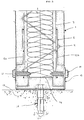
- Figure 1 shows a generally rectangular structural panel 1 comprising a core of polystyrene insulating material 2, which is reinforced by a steel wire lattice, thereby defining a panel care 6.
- the vertical members of the steel lattice 3 consist of first wire elements in spaced parallel relationship which are joined to respective adjacent elements by means of a plurality at spaced parallel members 4 perpendicular to the first wire elements, which in normal usage will be substantially horizontal, thereby forming a cage like structure on the surface of the insulating material 2.
- the panel core 6 is supported at each of its two lower corners by a fastening 5, which is described in greater detail hereinafter.
- the panel core 6 and the fastenings 5 are encapsulated on their exterior sides in concrete 7.
- the structural panel 1 so formed is then mounted in two substantially U-shaped brackets 8 which have been previously secured to, e.g., building foundations.
- the respective opposite vertical edges of the structural panel 1 are provided with a tongue 9 and a groove 10.
- Figure 2 shows a cross-sectional lower end view of the structural panel 1 with the fastening 5 in the installed position.
- the panel core 6 again comprises the insulating material 2 and steel lattice 3 and further comprises a member 11 passing back and forth through the insulating material 2, thereby forming a warren truss type structure, whereby the individual apices of the member 11 protrude beyond the surface plane of the steel lattice 3.
- the tie elements 4 are not visible.
- the panel core 6 is held in a fastening 5 having substantially vertical resilient arms 12a and 12b on opposite sides of the panel care 6 which arms engage with the steel lattice 3 and may be fastened to the lattice by means of Hartco clips or the like.
- the arms extend substantially horizontally outwardly towards the outer surface of the structural panel 1.
- a substantially horizontal connecting piece 13 joins the lower portion of the arms 12a and 12b to one another, which connecting piece has a raised central plateau 14, on which the panel core 6 rests.
- the core 6 and the fastening 5 are encapsulated in concrete such that the lower face of the horizontal connecting piece 13 is substantially free of concrete.
- the structural panel 1 thus formed is mounted in a substantially U-shaped bracket 15 having a cement mortar bed in the space between the upper surface at the bracket and the lower surface of the structural panel 1.
- the U-shaped bracket 15 is screwed to the structural panel by screws on each side of the panel, said screws 21 reaching into the insulating material 2.
- the U-shaped bracket is anchored to the floor by means of an anchor 16.
- a damp proof course 17 is provided between the lower surface of the U-shaped bracket 15 and the parts of the panel not held in the bracket and the floor or surface on which the panel is mounted.
- the panel core may comprise a series of vertical warren trusses having horizontal tie members joining each truss to its respective adjacent trusses, wherein the space between trusses is filled with stripe of polystyrene insulating material.
- the panel core may have various thicknesses depending on the amount of insulation required for the particular building.
- a typical panel is between 76mm and 150mm thick, up to 1500mm wide and 3000mm tall, i.e. each panel can be one storey high. It is also possible to increase the strength of the panel by increasing the diameter of the wire used to form the lattice.
- the insulating material is typically polystyrene, other materials such as mineral wool, phenolic foam or polyurethane may be used depending on the precise application. As the panel is relatively thin in comparison with a conventional structure, the floor space available in the building is increased.
- the panel cores 6 are encapsulated in concrete using split moulds to enable the correct thickness of concrete to be laid out for the lower face and to be screed before adding the panel.
- the concrete used should preferably be a fine aggregate concrete with a compressive strength in the range of 10 to 60 N/mm 2 , be free flowing and contain a waterproofing additive to improve resistance to environmental degradation.
- the concrete layer is typically 12-25mm thick. It would also be possible to produce a lightweight panel by using a lightweight aggregate such as FIBO expanded clay or Perlite. Such a lightweight panel is man handleable on site.
- Fire tests according TO BS 476 have shown that the panel has the following properties: stability (66 mins); integrity (50 mins); insulation (50 mins).
- the panel tested by 3.00m x 3.1 m high x 100mm thick, 22mm concrete thickness, load strength 6KN/m run. Surface spread of flame: Class 1.
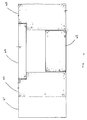
- FIG 3 shows a perspective view of the fastening 5 in the U-shaped bracket 15 having too substantially vertical arms 12a,b and connecting piece 13 having a raised central plateau 14.
- Each of the arms 12a,b has three rectangular openings 18,19,20.
- the two vertical openings 18,19 being situated above the horizontal opening 20.
- the openings serve to allow the screws 21 to be screwed into the panel.
- the U-shaped bracket 15 has an opening 22 an its horizontal section to receive the anchor 16.
- the structural panel 1 is mounted in two U-shaped channels which together extend over substantially the entire length of the lower edge of the panel.
- the U-shaped, channel is anchored to the floor by means of an anchor.
- a mortar cement bed would be placed between the upper surface of the channel and the lower surface of the structural panel.
- a damp proof course is provided between the lower surface of the channel and the floor.
- Figure 4 shows a schematic representation of a part of a building having a window opening constructed using panels made according to the invention.
- the walls of the building are constructed of storey high panels 41.
- the storey high panels adjacent to a window opening 42 43 have a small rectangular portion missing from the upper edge facing the opening, which is adapted to receive a lintel 44 using tongue and groove or notches.
- a spandrel panel 45 forms the lower edge of the opening and spans the gap between the panels 42,43.
- the lintel 44 is made in the same manner as the structural panel 1 but may have added re-inforcement in the form of steel rods or the like to increase its strength.
- the lintel may of course be used with conventional building systems.
- the thicker panels of the invention may be used as floor panels.
- the panels 41-45 may be finished by rendering to seal the wall against water ingress, possibly with further insulation between the render and the wall or may provide the internal skin of a traditional cavity wall construction, the cavity of which could itself be filled with insulating material.
- interstitial lattice elements are described as zig-zag, they could have a serpentine or triangular wave structure or similar.
Priority Applications (1)
| Application Number | Priority Date | Filing Date | Title |
|---|---|---|---|
| EP98200702A EP0940516A1 (fr) | 1998-03-06 | 1998-03-06 | Panneau de construction |
Applications Claiming Priority (1)
| Application Number | Priority Date | Filing Date | Title |
|---|---|---|---|
| EP98200702A EP0940516A1 (fr) | 1998-03-06 | 1998-03-06 | Panneau de construction |
Publications (1)
| Publication Number | Publication Date |
|---|---|
| EP0940516A1 true EP0940516A1 (fr) | 1999-09-08 |
Family
ID=8233445
Family Applications (1)
| Application Number | Title | Priority Date | Filing Date |
|---|---|---|---|
| EP98200702A Withdrawn EP0940516A1 (fr) | 1998-03-06 | 1998-03-06 | Panneau de construction |
Country Status (1)
| Country | Link |
|---|---|
| EP (1) | EP0940516A1 (fr) |
Cited By (6)
| Publication number | Priority date | Publication date | Assignee | Title |
|---|---|---|---|---|
| EP1106745A3 (fr) * | 1999-12-09 | 2001-08-22 | Schwörer Haus KG | Elément de plancher préfabriqué avec du polyuréthanne expansé et son procédé de fabrication |
| DE10310401B3 (de) * | 2003-03-07 | 2004-07-15 | Dieckhoff, Peter | Dämmplatte aus geschäumtem Kunststoff und Mehrschichten-Wandplatte |
| WO2011082501A1 (fr) * | 2010-01-05 | 2011-07-14 | Beuchat, Barros & Pfenniger | Procédé de fabrication de panneaux de cloison de type sandwich, panneau ainsi obtenu selon ledit procédé, ainsi que son montage dans un système de construction |
| CN101899935B (zh) * | 2009-05-26 | 2012-06-27 | 亨特道格拉斯建筑产品(中国)有限公司 | 内置滑块的预装型材盒式蜂窝板 |
| CN105544851A (zh) * | 2015-12-10 | 2016-05-04 | 上海宝岳住宅工业有限公司 | 一种预制夹心保温叠合墙板及制作方法 |
| CN105672561A (zh) * | 2016-03-15 | 2016-06-15 | 罗寅 | 自保温复合墙板及生产方法 |
Citations (4)
| Publication number | Priority date | Publication date | Assignee | Title |
|---|---|---|---|---|
| GB598690A (en) * | 1945-11-08 | 1948-02-24 | Ernest Goodall Malthouse | Improvements in or relating to precast building units |
| US3979863A (en) * | 1975-05-30 | 1976-09-14 | Bearingwall Systems, Inc. | Modular precast concrete wall panels in building construction |
| US4117639A (en) * | 1977-06-29 | 1978-10-03 | Butler Manufacturing Company | Reinforced insulated concrete building panel |
| DE2843324A1 (de) * | 1977-12-05 | 1979-06-07 | Covington Bros Building Syst | Baupaneel |
-
1998
- 1998-03-06 EP EP98200702A patent/EP0940516A1/fr not_active Withdrawn
Patent Citations (4)
| Publication number | Priority date | Publication date | Assignee | Title |
|---|---|---|---|---|
| GB598690A (en) * | 1945-11-08 | 1948-02-24 | Ernest Goodall Malthouse | Improvements in or relating to precast building units |
| US3979863A (en) * | 1975-05-30 | 1976-09-14 | Bearingwall Systems, Inc. | Modular precast concrete wall panels in building construction |
| US4117639A (en) * | 1977-06-29 | 1978-10-03 | Butler Manufacturing Company | Reinforced insulated concrete building panel |
| DE2843324A1 (de) * | 1977-12-05 | 1979-06-07 | Covington Bros Building Syst | Baupaneel |
Cited By (7)
| Publication number | Priority date | Publication date | Assignee | Title |
|---|---|---|---|---|
| EP1106745A3 (fr) * | 1999-12-09 | 2001-08-22 | Schwörer Haus KG | Elément de plancher préfabriqué avec du polyuréthanne expansé et son procédé de fabrication |
| DE10310401B3 (de) * | 2003-03-07 | 2004-07-15 | Dieckhoff, Peter | Dämmplatte aus geschäumtem Kunststoff und Mehrschichten-Wandplatte |
| CN101899935B (zh) * | 2009-05-26 | 2012-06-27 | 亨特道格拉斯建筑产品(中国)有限公司 | 内置滑块的预装型材盒式蜂窝板 |
| WO2011082501A1 (fr) * | 2010-01-05 | 2011-07-14 | Beuchat, Barros & Pfenniger | Procédé de fabrication de panneaux de cloison de type sandwich, panneau ainsi obtenu selon ledit procédé, ainsi que son montage dans un système de construction |
| CN105544851A (zh) * | 2015-12-10 | 2016-05-04 | 上海宝岳住宅工业有限公司 | 一种预制夹心保温叠合墙板及制作方法 |
| CN105544851B (zh) * | 2015-12-10 | 2017-08-11 | 上海宝岳住宅工业有限公司 | 一种预制夹心保温叠合墙板及制作方法 |
| CN105672561A (zh) * | 2016-03-15 | 2016-06-15 | 罗寅 | 自保温复合墙板及生产方法 |
Similar Documents
| Publication | Publication Date | Title |
|---|---|---|
| US7100336B2 (en) | Concrete building panel with a low density core and carbon fiber and steel reinforcement | |
| US4669240A (en) | Precast reinforced concrete wall panels and method of erecting same | |
| US7627997B2 (en) | Concrete foundation wall with a low density core and carbon fiber and steel reinforcement | |
| US7254925B2 (en) | Insulated wall assembly | |
| US5526625A (en) | Building panel and buildings using the panel | |
| AU2007204470B2 (en) | Construction made of individual components | |
| US20210301528A1 (en) | Systems and methods for constructing a single-storey building | |
| US20090113820A1 (en) | Prefabricated wall panel system | |
| US5799453A (en) | Structure and method of fabrication | |
| EP2646632B1 (fr) | Immeuble d'appartements a plusieurs etages et procede de construction d'un tel immeuble | |
| US20050115185A1 (en) | Masonry block constructions with polymeric coating | |
| EA013175B1 (ru) | Наружная стена многоэтажного каркасного здания системы аркос и способ ее возведения | |
| EP0048728A1 (fr) | Systeme de construction base sur des plaques de beton minces et elements de cassettes pour la mise en oeuvre du systeme. | |
| EP0940516A1 (fr) | Panneau de construction | |
| AU5120393A (en) | Improvements in/or relating to insulated construction panelsand/or methods of manufacturing such panels and/or methods of construction using such panels | |
| CN115928909A (zh) | 短肢剪力墙装配式轻钢组合桁架承托钢丝网架砂浆-珍珠岩-聚苯复合围护墙及作法 | |
| KR19980058501U (ko) | 조립식 pc콘크리트 벽체판넬 | |
| GB2317404A (en) | A structural panel | |
| WO2010138993A1 (fr) | Système de construction modulaire | |
| CN219327204U (zh) | 钢框架装配式轻钢钢丝网架砂浆-珍珠岩-聚苯围护墙 | |
| CN210562584U (zh) | 一种装配式建筑结构 | |
| WO2007012863A1 (fr) | Panneaux de construction et construction de bâtiments à l’aide de ces panneaux | |
| CN116290479A (zh) | 钢框架装配式轻钢组合桁架承托钢丝网架砂浆-珍珠岩-聚苯复合围护墙及作法 | |
| CN116044052A (zh) | 装配式带窗洞轻钢组合桁架承托钢丝网架砂浆-珍珠岩-聚苯复合剪力墙及作法 | |
| CN115949157A (zh) | 装配式剪力墙体系及施工方法 |
Legal Events
| Date | Code | Title | Description |
|---|---|---|---|
| PUAI | Public reference made under article 153(3) epc to a published international application that has entered the european phase |
Free format text: ORIGINAL CODE: 0009012 |
|
| AK | Designated contracting states |
Kind code of ref document: A1 Designated state(s): AT BE CH DE DK ES FI FR GR IE IT LI NL PT SE |
|
| AX | Request for extension of the european patent |
Free format text: AL;LT;LV;MK;RO;SI |
|
| 17P | Request for examination filed |
Effective date: 20000308 |
|
| AKX | Designation fees paid |
Free format text: AT BE CH DE DK ES FI FR GR IE IT LI NL PT SE |
|
| AXX | Extension fees paid |
Free format text: LT PAYMENT 20000308 |
|
| 17Q | First examination report despatched |
Effective date: 20021014 |
|
| STAA | Information on the status of an ep patent application or granted ep patent |
Free format text: STATUS: THE APPLICATION IS DEEMED TO BE WITHDRAWN |
|
| 18D | Application deemed to be withdrawn |
Effective date: 20110304 |