EP0940259B1 - Elektrische Erneuerung für Tintenzuführsystem - Google Patents
Elektrische Erneuerung für Tintenzuführsystem Download PDFInfo
- Publication number
- EP0940259B1 EP0940259B1 EP99301566A EP99301566A EP0940259B1 EP 0940259 B1 EP0940259 B1 EP 0940259B1 EP 99301566 A EP99301566 A EP 99301566A EP 99301566 A EP99301566 A EP 99301566A EP 0940259 B1 EP0940259 B1 EP 0940259B1
- Authority
- EP
- European Patent Office
- Prior art keywords
- ink
- printer
- ink container
- memory device
- contacts
- Prior art date
- Legal status (The legal status is an assumption and is not a legal conclusion. Google has not performed a legal analysis and makes no representation as to the accuracy of the status listed.)
- Expired - Lifetime
Links
Images


Classifications
-
- B—PERFORMING OPERATIONS; TRANSPORTING
- B41—PRINTING; LINING MACHINES; TYPEWRITERS; STAMPS
- B41J—TYPEWRITERS; SELECTIVE PRINTING MECHANISMS, i.e. MECHANISMS PRINTING OTHERWISE THAN FROM A FORME; CORRECTION OF TYPOGRAPHICAL ERRORS
- B41J2/00—Typewriters or selective printing mechanisms characterised by the printing or marking process for which they are designed
- B41J2/005—Typewriters or selective printing mechanisms characterised by the printing or marking process for which they are designed characterised by bringing liquid or particles selectively into contact with a printing material
- B41J2/01—Ink jet
- B41J2/17—Ink jet characterised by ink handling
- B41J2/175—Ink supply systems ; Circuit parts therefor
- B41J2/17503—Ink cartridges
- B41J2/17543—Cartridge presence detection or type identification
- B41J2/17546—Cartridge presence detection or type identification electronically
-
- B—PERFORMING OPERATIONS; TRANSPORTING
- B41—PRINTING; LINING MACHINES; TYPEWRITERS; STAMPS
- B41J—TYPEWRITERS; SELECTIVE PRINTING MECHANISMS, i.e. MECHANISMS PRINTING OTHERWISE THAN FROM A FORME; CORRECTION OF TYPOGRAPHICAL ERRORS
- B41J2/00—Typewriters or selective printing mechanisms characterised by the printing or marking process for which they are designed
- B41J2/005—Typewriters or selective printing mechanisms characterised by the printing or marking process for which they are designed characterised by bringing liquid or particles selectively into contact with a printing material
- B41J2/01—Ink jet
- B41J2/135—Nozzles
- B41J2/165—Preventing or detecting of nozzle clogging, e.g. cleaning, capping or moistening for nozzles
- B41J2/16517—Cleaning of print head nozzles
- B41J2/16535—Cleaning of print head nozzles using wiping constructions
- B41J2/16538—Cleaning of print head nozzles using wiping constructions with brushes or wiper blades perpendicular to the nozzle plate
-
- B—PERFORMING OPERATIONS; TRANSPORTING
- B41—PRINTING; LINING MACHINES; TYPEWRITERS; STAMPS
- B41J—TYPEWRITERS; SELECTIVE PRINTING MECHANISMS, i.e. MECHANISMS PRINTING OTHERWISE THAN FROM A FORME; CORRECTION OF TYPOGRAPHICAL ERRORS
- B41J2/00—Typewriters or selective printing mechanisms characterised by the printing or marking process for which they are designed
- B41J2/005—Typewriters or selective printing mechanisms characterised by the printing or marking process for which they are designed characterised by bringing liquid or particles selectively into contact with a printing material
- B41J2/01—Ink jet
- B41J2/17—Ink jet characterised by ink handling
- B41J2/175—Ink supply systems ; Circuit parts therefor
- B41J2/17503—Ink cartridges
- B41J2/17506—Refilling of the cartridge
-
- B—PERFORMING OPERATIONS; TRANSPORTING
- B41—PRINTING; LINING MACHINES; TYPEWRITERS; STAMPS
- B41J—TYPEWRITERS; SELECTIVE PRINTING MECHANISMS, i.e. MECHANISMS PRINTING OTHERWISE THAN FROM A FORME; CORRECTION OF TYPOGRAPHICAL ERRORS
- B41J2/00—Typewriters or selective printing mechanisms characterised by the printing or marking process for which they are designed
- B41J2/005—Typewriters or selective printing mechanisms characterised by the printing or marking process for which they are designed characterised by bringing liquid or particles selectively into contact with a printing material
- B41J2/01—Ink jet
- B41J2/17—Ink jet characterised by ink handling
- B41J2/175—Ink supply systems ; Circuit parts therefor
- B41J2/17503—Ink cartridges
- B41J2/1752—Mounting within the printer
- B41J2/17523—Ink connection
-
- B—PERFORMING OPERATIONS; TRANSPORTING
- B41—PRINTING; LINING MACHINES; TYPEWRITERS; STAMPS
- B41J—TYPEWRITERS; SELECTIVE PRINTING MECHANISMS, i.e. MECHANISMS PRINTING OTHERWISE THAN FROM A FORME; CORRECTION OF TYPOGRAPHICAL ERRORS
- B41J2/00—Typewriters or selective printing mechanisms characterised by the printing or marking process for which they are designed
- B41J2/005—Typewriters or selective printing mechanisms characterised by the printing or marking process for which they are designed characterised by bringing liquid or particles selectively into contact with a printing material
- B41J2/01—Ink jet
- B41J2/17—Ink jet characterised by ink handling
- B41J2/175—Ink supply systems ; Circuit parts therefor
- B41J2/17503—Ink cartridges
- B41J2/17526—Electrical contacts to the cartridge
-
- B—PERFORMING OPERATIONS; TRANSPORTING
- B41—PRINTING; LINING MACHINES; TYPEWRITERS; STAMPS
- B41J—TYPEWRITERS; SELECTIVE PRINTING MECHANISMS, i.e. MECHANISMS PRINTING OTHERWISE THAN FROM A FORME; CORRECTION OF TYPOGRAPHICAL ERRORS
- B41J2/00—Typewriters or selective printing mechanisms characterised by the printing or marking process for which they are designed
- B41J2/005—Typewriters or selective printing mechanisms characterised by the printing or marking process for which they are designed characterised by bringing liquid or particles selectively into contact with a printing material
- B41J2/01—Ink jet
- B41J2/17—Ink jet characterised by ink handling
- B41J2/175—Ink supply systems ; Circuit parts therefor
- B41J2/17503—Ink cartridges
- B41J2/17543—Cartridge presence detection or type identification
- B41J2/1755—Cartridge presence detection or type identification mechanically
-
- B—PERFORMING OPERATIONS; TRANSPORTING
- B41—PRINTING; LINING MACHINES; TYPEWRITERS; STAMPS
- B41J—TYPEWRITERS; SELECTIVE PRINTING MECHANISMS, i.e. MECHANISMS PRINTING OTHERWISE THAN FROM A FORME; CORRECTION OF TYPOGRAPHICAL ERRORS
- B41J2/00—Typewriters or selective printing mechanisms characterised by the printing or marking process for which they are designed
- B41J2/005—Typewriters or selective printing mechanisms characterised by the printing or marking process for which they are designed characterised by bringing liquid or particles selectively into contact with a printing material
- B41J2/01—Ink jet
- B41J2/17—Ink jet characterised by ink handling
- B41J2/175—Ink supply systems ; Circuit parts therefor
- B41J2/17503—Ink cartridges
- B41J2/17553—Outer structure
-
- B—PERFORMING OPERATIONS; TRANSPORTING
- B41—PRINTING; LINING MACHINES; TYPEWRITERS; STAMPS
- B41J—TYPEWRITERS; SELECTIVE PRINTING MECHANISMS, i.e. MECHANISMS PRINTING OTHERWISE THAN FROM A FORME; CORRECTION OF TYPOGRAPHICAL ERRORS
- B41J2/00—Typewriters or selective printing mechanisms characterised by the printing or marking process for which they are designed
- B41J2/005—Typewriters or selective printing mechanisms characterised by the printing or marking process for which they are designed characterised by bringing liquid or particles selectively into contact with a printing material
- B41J2/01—Ink jet
- B41J2/17—Ink jet characterised by ink handling
- B41J2/175—Ink supply systems ; Circuit parts therefor
- B41J2/17566—Ink level or ink residue control
-
- B—PERFORMING OPERATIONS; TRANSPORTING
- B41—PRINTING; LINING MACHINES; TYPEWRITERS; STAMPS
- B41J—TYPEWRITERS; SELECTIVE PRINTING MECHANISMS, i.e. MECHANISMS PRINTING OTHERWISE THAN FROM A FORME; CORRECTION OF TYPOGRAPHICAL ERRORS
- B41J25/00—Actions or mechanisms not otherwise provided for
- B41J25/34—Bodily-changeable print heads or carriages
-
- B—PERFORMING OPERATIONS; TRANSPORTING
- B41—PRINTING; LINING MACHINES; TYPEWRITERS; STAMPS
- B41J—TYPEWRITERS; SELECTIVE PRINTING MECHANISMS, i.e. MECHANISMS PRINTING OTHERWISE THAN FROM A FORME; CORRECTION OF TYPOGRAPHICAL ERRORS
- B41J2/00—Typewriters or selective printing mechanisms characterised by the printing or marking process for which they are designed
- B41J2/005—Typewriters or selective printing mechanisms characterised by the printing or marking process for which they are designed characterised by bringing liquid or particles selectively into contact with a printing material
- B41J2/01—Ink jet
- B41J2/17—Ink jet characterised by ink handling
- B41J2/175—Ink supply systems ; Circuit parts therefor
- B41J2/17566—Ink level or ink residue control
- B41J2002/17569—Ink level or ink residue control based on the amount printed or to be printed
-
- B—PERFORMING OPERATIONS; TRANSPORTING
- B41—PRINTING; LINING MACHINES; TYPEWRITERS; STAMPS
- B41J—TYPEWRITERS; SELECTIVE PRINTING MECHANISMS, i.e. MECHANISMS PRINTING OTHERWISE THAN FROM A FORME; CORRECTION OF TYPOGRAPHICAL ERRORS
- B41J2/00—Typewriters or selective printing mechanisms characterised by the printing or marking process for which they are designed
- B41J2/005—Typewriters or selective printing mechanisms characterised by the printing or marking process for which they are designed characterised by bringing liquid or particles selectively into contact with a printing material
- B41J2/01—Ink jet
- B41J2/17—Ink jet characterised by ink handling
- B41J2/175—Ink supply systems ; Circuit parts therefor
- B41J2/17566—Ink level or ink residue control
- B41J2002/17573—Ink level or ink residue control using optical means for ink level indication
-
- B—PERFORMING OPERATIONS; TRANSPORTING
- B41—PRINTING; LINING MACHINES; TYPEWRITERS; STAMPS
- B41J—TYPEWRITERS; SELECTIVE PRINTING MECHANISMS, i.e. MECHANISMS PRINTING OTHERWISE THAN FROM A FORME; CORRECTION OF TYPOGRAPHICAL ERRORS
- B41J2/00—Typewriters or selective printing mechanisms characterised by the printing or marking process for which they are designed
- B41J2/005—Typewriters or selective printing mechanisms characterised by the printing or marking process for which they are designed characterised by bringing liquid or particles selectively into contact with a printing material
- B41J2/01—Ink jet
- B41J2/17—Ink jet characterised by ink handling
- B41J2/175—Ink supply systems ; Circuit parts therefor
- B41J2/17566—Ink level or ink residue control
- B41J2002/17576—Ink level or ink residue control using a floater for ink level indication
Definitions
- This invention relates in general to refurbishing printer ink containers and in particular to refurbishing the electrical information storage device in printer ink containers.
- One type of prior art ink-jet printer has a printhead mounted to a carriage that is moved back and forth over print media, such as paper. As the printhead passes over appropriate locations on the printing surface, a control system activates ink-jets on the printhead to eject ink drops onto the print media to form desired images and characters. To work properly, such printers must have a reliable supply of ink for the printhead.
- ink-jet printer uses a disposable ink pen that is mounted to and moves with the carriage.
- the ink reservoir portion of the ink pen is replaceable separate from the ink pen.
- the entire printhead and ink reservoir are replaced as a unit once the ink is depleted.
- Another category of printer uses reservoirs that are not located on the carriage. In this category of printer the reservoir intermittently replenishes the printhead with ink. The printhead travels to a stationary reservoir periodically for replenishment. Another type makes use of a replaceable ink reservoir connected to the printhead by a fluid conduit. The printhead is replenished with ink through this fluid conduit.
- Another function for the memory device discussed in US 5,812,156 is to prevent the use of the cartridge after the supply of ink is depleted. Operating a printer when the reservoir has been depleted of ink can damage or destroy the printhead portion of the cartridge.
- the memory devices concerned with this application are associated with the ink container and are updated with information relating to the current amount of ink remaining in the reservoir. When a new ink container is installed, the printer will read information from the memory device, which indicates the amount of ink remaining in the reservoir. During usage, the printer counts the drops of ink being used and updates the memory device associated with the ink container to indicate how much ink is remaining in the ink containers.
- this type of memory device When the ink is substantially depleted, this type of memory device will provide a signal to the printer which indicates that the reservoir is out of ink or low in ink. When substantially depleted of ink, these ink reservoirs are typically discarded and a new ink reservoir along with a new memory device is installed.
- EP 0789322 discloses a replaceable ink cartridge for a printer/copier apparatus.
- the cartridge includes an internal reservoir for holding a supply of ink and a serial memory chip 76.
- the memory chip enables input/output of data over a single access wire. Also, by coding of the memory with an ink supply identifier, it can be determined by the printer when the ink supply will run out.
- This application describes methods of refurbishing an ink reservoir that has a memory device that has been altered during usage as claimed in claims 1 to 14 hereinafter. For example; after an ink reservoir is used in a printing system and partially depleted of ink the memory device associated with this ink reservoir reflects this partially depleted condition. Refurbishment of this ink reservoir that involves only refilling the ink reservoir is insufficient because the memory device reflects a partially depleted condition.
- One aspect of the technique of the present invention makes use of that a new source of signals when electrically connected to the printer station terminals, provide a signal indicative of more available ink than the partially depleted condition.
- the source of signals provides enabling information which allows the reservoir to be refilled and used again.
- the source of signals may be a second memory device similar to the original. Alternately, this source of signals may be an emulator which is an electronic circuit which functions in a similar manner to the original memory device.
- the memory device and its associated electrical contacts are formed on a substrate that is bonded to the cartridge housing.
- a second refurbishment technique of the present invention involves removing original substrate, including the memory device and the contacts, by prying it from the cartridge housing. A new substrate with new electrical contacts and a new memory device are bonded to the cartridge housing in the same place.
- a new substrate with a new source of signals and new set of electrical contacts are bonded on top of the first substrate.
- the new substrate covers and insulates the original contacts, blocking them from contacting the mating contacts of the printer.
- a fourth refurbishment method of the present invention electrical continuity between the memory device and the contacts is severed.
- the new source of signals is electrically connected to the portion of the original contacts which are electrically isolated from the original memory device.
- the new source of signals is mounted to the cartridge, or if desired, remotely located from the cartridge.
- This invention provides also a refurbished ink container as defined in claims 15, 16.
- the present invention comprises methods for electrically refurbishing ink containers for printing systems
- the invention may be more clearly understood by first thoroughly discussing one of the printing systems for which this invention may be adapted.
- Figure 1 illustrates a portion of an ink-jet printing system 10 having an original equipment ink cartridge or container 12.
- the ink-jet printing system 10 includes an ink container receiving station 14, an ink-jet printhead 16, and a print controller 18. Printing is accomplished by the ejection of ink from the printhead 16 under the control of print controller 18.
- Printhead 16 is connected to the controller 18 by link 19 for controlling ejection of ink.
- Ink is provided to the printhead 16 by way of a fluid conduit 21, which joins the printhead 16 to the receiving station 14.
- Ink container 12 includes a fluid outlet 20 which communicates with a fluid reservoir 22.
- Ink container 12 also includes electrical terminals or contacts 24 which communicate with an information storage device 26 such as a memory device.
- Fluid outlet 20 and electrical contacts 24 allow ink container 12 to interconnect with a fluid inlet 28 and electrical contacts 30, respectively, on receiving station 14.
- Receiving station 14 enables ink to be transferred from fluid reservoir 22 to printhead 16 via fluid conduit 21.
- receiving station 14 allows the transfer of information between information storage device 26 and print controller 18 via a link 32.
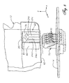
- printer 10 is capable of holding four ink containers 12 at the same time.
- Printer 10 includes a tray 40 for holding a paper supply.
- a sheet of paper from tray 40 is fed into printer 10 using a sheet feeder (not shown).
- the paper passes through a print zone 42 whereupon a scanning carriage 44 containing one or more printheads 16 is scanned across the sheet for printing a swath of ink thereon.
- the sheet of paper is stepped through the print zone 42 as the scanning carriage 44 prints a series of swaths of ink to form images thereon.
- the sheet is positioned into an output tray 46.
- the positioning of paper supply 40 and output tray 46 can vary depending on the particular sheet feed mechanism used.
- Scanning carriage 44 slides through the print zone 42 on a scanning mechanism which includes a slide rod 48.
- a positioning means such as a coded strip (not shown) is used in conjunction with a photo detector for precisely positioning scanning carriage 44.
- a stepper motor (not shown), connected to scanning carriage 44 using a conventional drive belt and pulley arrangement, is used for transporting scanning carriage 44 across print zone 42.
- a ribbon cable (not shown) carries electrical signals to the scanning carriage 44 for selectively energizing the printheads 16 ( Figures 1 and 2). As the printheads 16 are selectively energized, ink of a selected color is ejected onto the print media as scanning carriage 44 passes through print zone 42.
- Each ink container 12 has its own electrical contacts 24 and fluid outlet 20 (Figure 3).
- Ink containers 12 may be referred to as an off-axis ink supply since the ink supply is spaced from a scan axis defined by scanning carriage 44.
- ink containers 12 are typically separate ink containers for each color with a container for black ink.
- ink container 12 for the embodiment shown in Figure 2 is an ink container 54 for black ink, an ink container 56 for yellow ink, an ink container 58 for magenta ink, and an ink container 60 for cyan ink.
- Receiving station 14 contains mechanical, fluid and electrical interfaces for each ink container 12. Ink passes through the fluid interfaces in receiving station 14, fluid conduits 21 and then to printheads 16 on print scanning carriage 44.
- receiving station 14 has four separate electrical connector posts 70, one for each of the cartridges 12.
- the four electrical contacts 30 are mounted to each electrical connector post 70, as shown in Figure 8.
- Each connector post 70 protrudes upwardly and has a tapered leading edge portion 71.
- Contacts 30 are outwardly spring biased from connector post 70.
- Ink container 12 contains a supply of media marking fluid such as ink.
- ink container 12 has fluid outlet 20 and electrical contacts 24.
- ink container has aligning ribs 62 on each side edge. Aligning ribs 62 mate with slots 66 on receiving station 14 to assist in aligning ink container 12 for insertion into receiving station 14. Aligning ribs 62 and slots 66 also provide a keying function to ensure that ink container 12 contains ink having the proper parameters, such as color and ink compatibility with printer 10.
- Ink container also has latch shoulders 64 on each side edge, as shown in Figure 3, which are engaged by resilient latches 68 mounted on the sidewalls of receiving station 14.
- ink container 12 is aligned and inserted into receiving station 14, latches 68 on receiving station 14 engage corresponding latch shoulders 64 on ink container 12. Insertion of ink container 12 into receiving station 14 forms both electrical and fluid interconnects between contacts 24 and 30, and ports 20 and 28, respectively.
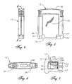
- Ink container 12 is shown in detail in Figures 4-7.
- Ink container 12 includes an outer surface or housing 72 having a leading edge or end 74 and a trailing edge or end 76 relative to the direction of insertion of ink container 12 into receiving station 14.
- Contacts 24 are located in a small cavity 80 on a lower side of housing 72 adjacent to leading edge 74.
- contacts 24 are metal conductive layers disposed on a nonconductive substrate 78 such as epoxy and fiberglass.
- traces or leads 81 are disposed on substrate 78, each extending from one of the contacts 24.
- Memory device 26 is mounted to substrate 78, and the terminals of memory device 26 are joined to the traces 81. This places terminals of the memory device 26 in electrical continuity with contacts 24.
- a protective coating (not shown), such as epoxy, is used to encapsulate memory device 26 after its terminals are bonded to traces 81.
- a backside of the substrate 78, opposite the contacts 24 and memory device 26, is bonded by adhesive or swaged to a sidewall of cavity 80 ( Figure 7).
- cavity 80 is sized to be small enough to reduce the possibility of fingers from entering cavity 80.
- the proper sizing of the entrance is important for preventing contamination of contacts 24 during handling of ink container 12.
- cavity 80 closely receives one of the connector posts 70. As ink container 12 is inserted into printer 10, contacts 30 are compressed against contacts 24 to form a low resistance electrical connection between printer 10 and memory device 26.
- Each ink container 12 has ink related parameters which are unique to the particular ink container and the ink within the ink container. These parameters are stored in the information storage device 26 associated with the ink container 12. The parameters in the information storage device 26 are provided to the controller 18 automatically without requiring the user to configure printer 10 for the particular ink container 12 installed.
- Memory device 26 has a read-only section, a write-once section, and a multiple write/erase section. The read only section is write enabled during the initial installation. When the cartridge is first installed in the printer 10, the printer 10 reads ink container information such as the manufacturer identity, part identification, date code of ink supply, system coefficients, service mode and ink supply size.
- the printer 10 then stores the installation date in the read only section of storage device 26, then initiates a write protect feature to assure that the information in the read-only section remains the same.
- the initial installation date is used by the printer 10 to determine if an ink container has been installed for an extended period of time which, if long enough, can reduce print quality.
- the write once section is a portion of memory which can be written to by printer 10 only one time.
- the multiple write/erase section can be written to and erased repeatedly. Both of these sections deal with storing information concerning current ink quantity. As will be explained below, the coarse bit information is stored in the write once section and the fine bit data is stored in the multiple write/erase section.
- controller 18 Upon insertion of ink container 12 into printing system 10, controller 18 reads parameter information from information storage device 26 for controlling various printing functions. For example, controller 18 uses parameter information to compute an estimate of remaining ink. If the ink remaining is less than a low ink threshold volume, a message is provided to the user indicating such. Further, when a substantial portion of the ink below the threshold volume is consumed, controller 18 can disable printing system 10 to prevent operation of the printhead 16 without a supply of ink. Printhead 16 operation without ink can result in reduction of printhead reliability or catastrophic failure of the printhead 16. Controller 18 can also provide notice to the user when the ink is beyond its shelf life so that ink container 12 can be replaced to ensure maximum print quality.
- the printing system 10 reads initial volume information from the memory device 26 associated with the ink container 12. As ink is used during printing this ink is monitored by the printing system 10 and the memory device 26 is updated to contain information relating to remaining ink in the ink container 12. The printing system 10 thereafter monitors the level of deliverable ink in ink container 12 via memory device 26. In a preferred embodiment, data is transferred between the printer 10 and the memory device 26 in serial fashion using the single data line 24 relative to ground.
- the volume information includes the following: (1) initial supply size data in a write protected portion of memory, (2) coarse ink level data stored in write once portion of memory, and (3) fine ink level data stored in a write/erase portion of memory.
- the initial supply size data is indicative of the amount of deliverable ink initially present in ink container 12.
- the coarse ink level data includes a number of write once bits that each correspond to some fraction of the deliverable ink initially present in ink container 12. In a first preferred embodiment, eight coarse ink level bits each corresponding to one eighth of the deliverable ink initially in ink container 12. In a second preferred embodiment, to be used in the discussion that follows, seven coarse ink level bits each correspond to one eighth of the deliverable ink initially present in ink container 12 and one coarse ink level bit corresponds to an out of ink condition. However, more or less coarse bits can be used, depending on the accuracy desired for a coarse ink level counter.
- the fine ink level data is indicative of a fine bit binary number that is proportional to a fraction of one eighth of the volume of the deliverable ink initially present in ink container 12.
- the entire range of the fine bit binary number is equivalent to one coarse ink level bit. This will be further explained below.
- Printing system 10 reads the initial supply size data and calculates the amount or volume of deliverable ink initially present in ink container 12.
- the drop volume ejected by the printhead 16 is determined by printing system 10 by reading parameters and/or performing calculations.
- the printing system 10 uses the initial volume of deliverable ink in ink container 12 and the drop volume of printhead 16, the printing system 10 calculates the fraction of the initial deliverable ink volume that each drop represents. This enables the printing system 10 to monitor the fraction of the initial volume of deliverable ink remaining in ink container 12.
- printing system 10 While printing, printing system 10 maintains a drop count equal to the number of ink drops that have been ejected by printhead 16. After printing system 10 has printed a small amount, typically one page, it converts the drop count to a number of increments or decrements of the fine bit binary number. This conversion utilizes the fact that the entire range of the fine bit binary number corresponds to one eighth of the initial volume of deliverable ink in ink container 12. Each time the fine bit binary number is fully decremented or incremented, the printing system 10 writes to one of the coarse ink level bits to "latch down" the bit.
- Printing system 10 periodically queries the coarse and fine ink level bits to determine the fraction of the initial deliverable ink that is remaining in ink container 12. Printing system 10 can then provide a "gas gauge” or other indication to a user of printing system 10 that is indicative of the ink level in ink container 12. In a preferred embodiment, the printing system provides a "low ink warning" when seventh (second to last) coarse ink level bit is set. Also in a preferred embodiment, the printing system sets the last coarse ink level bit when the ink container 12 is substantially depleted of ink. This last coarse ink level bit is referred to as an "ink out” bit. Upon querying the coarse ink level bits, the printing system interprets a "latched down" ink out bit as an "ink out” condition for ink container 12.
- printer 10 In printing system 10, the transfer of data between printer 10 and memory device 26 is in serial fashion on the single data line relative to ground. As explained above, while the ink in ink container 12 is being depleted, memory device 26 stores data which is indicative of its initial and current states. Printer 10 updates memory device 26 to indicate the volume of ink remaining. When most or substantially all of the deliverable ink has been depleted, printer 10 alters memory device 26 to allow ink container 12 to provide an "ink out" signal. Printer 10 may respond by stopping printing with ink container 12. At that point, the user will insert a new ink container 12 or one that has been refilled and electrically refurbished in accordance with this invention.
- Ink container 12 is fluidically refurbished by refilling it with ink. After the ink container 12 is partially depleted of ink, the memory device 26 that contains remaining ink. As explained above, the coarse bit counter reflecting remaining ink is stored in the write once section of memory 26. Consequently, refilling the ink container 12 results in the alteration of the amount of ink remaining but does not change the coarse bit counter indicating the amount of remaining ink. Therefore, the memory device 26 does not provide accurate ink remaining information resulting in improper low ink condition signals. In addition, because the refilled ink does not have the same ink parameters as those ink parameters stored in the memory device 26 then the printing system 10 can not properly compensate for this refilled ink to ensure high print quality.
- the purpose of this invention is to electrically refurbish ink container 12 so that the benefits previously provided by memory device 26 still exist.
- the pre-existing data in memory device 26 is prevented from further communication with printer 10 when cartridge 12 is installed again.
- all of the data in memory device 26 is erased. This can be accomplished by exposing the memory device 26 to an energy source such as an x-ray or electric field. This energy source, if sufficient, resets the data in memory device 26.
- the reservoir of ink container 12 is then refilled.
- memory device 26 can be reprogrammed to reflect parameters of the refilled ink container 12.
- the printing system operates with the ink container 12 in a manner similar to the initial ink container.
- memory device 26 is disabled and replaced with an identical one or with an emulator 84 (Fig. 10).
- the new memory device 26 may be an emulator or a substantial replica of the original memory device 26.
- Emulator 84 is an electronic circuit that is functionally equivalent to memory device 26 in providing information to printer 10 ( Figure 1) although structurally this device may be very different. Emulator 84 would likely have a portion that functions as a memory and would likely provide information regarding the volume of reservoir 22, the type of ink, color, etc.
- emulator 84 may be reset in a different manner whenever a new ink supply is provided. Further, emulator 84 may be configured to provide information to printer 10 which enables it to operate regardless of the actual condition of the ink in ink reservoir 22.
- the new source of signals such as emulator 84 or a new memory device 26, must be provided with the data required for proper operation of printer 10.
- the new source of signals must be able to communicate with printer 10 over a single wire input/output in serial fashion.
- the data provided by the memory device 26 is used by printer 10 to generate an indication of the volume of ink available.
- the first memory device 26 will be removed from cavity 80 of housing 72 (Fig. 7).
- Substrate 78 (Fig. 9), along with memory device 26 and contacts 24, may be pried off or otherwise removed as a unit from cavity 80.
- a new substrate 78, having a new memory device 26 or emulator 84 and contacts 24, may be adhesively bonded to a sidewall of cavity 80 in the same place that held the original substrate 78, memory device 26 and contacts 24.
- a substrate 78 containing only a new set of contacts 24 may be mounted in cavity 80.
- the new memory device 26 or emulator 84 may be mounted at another place on housing 72 of refurbished cartridge 12 and connected to the new set of contacts 24 by leads.
- emulator 84 may also be located remotely from or not immediately adjacent to printer 10 and connected by leads 82 to contacts 24 within cavity 80.
- Another refurbishment method allows the original substrate 78, memory device 26 and contacts 24 to remain in place.
- a new substrate 78, along with a new memory device 26 and contacts 24, will be bonded on top of the original memory device 26 and contacts 24.
- the original contacts 24 will not be able to electrically engage printer contacts 30 (Fig. 8) because they will be covered and insulated from engagement by the new substrate 78.
- This technique may be performed several times before electrical connection with printer 10 becomes difficult due to space constraints.
- Cavity 80 becomes effectively smaller each time a new substrate 78, along with new contacts 24 and a new memory device 26, are installed on top of an earlier set.
- a usable portion of the original contacts 24 remains in place and is electrically separated from the original memory device 26.
- a cut is made through substrate 78 transversely across one or more contacts 24 with a sharp object such as knife 85 as shown in Figure 9.
- the cut divides substrate 78 into retained and disposable portions 78a, 78b, the retained portion 78a of which contains a significant portion of contacts 24.
- Substrate disposable portion 78b contains memory device 26, along with traces 81 and a small adjacent part of contacts 24. This cut severs electrical continuity between the four terminals of memory device 26 with the part of contacts 24 contained on the substrate retained portion 78a.
- the size of contacts 24 on substrate retained portion 78a would be smaller than the original contacts 24, they are of adequate size to mate with printer contacts 30 ( Figure 8).
- the disposable substrate portion 78b along with the first memory device 26, traces 81, and the part of contacts 24 contained thereon.
- a new memory device 26 may then be mounted adjacent to or on the original contacts 24 contained on the retained substrate portion 78a, with its terminals connected to them.
- the new memory device 26 could be mounted elsewhere on housing 72 other than cavity 80 (Fig. 7) or even remotely from printer 10 and connected to original contacts 24 by leads. If an emulator 84 is used rather than the memory device 26, it too may be mounted on housing 72 in a place other than in cavity 80, or it may be mounted in cavity 80 adjacent to or on substrate retained portion 78a.
- the contacts 24 on substrate retained portion 78a may be connected to leads 82 that are attached to a remotely located emulator 84.
- Contacts 24 may be connected to leads 82 or to leads or terminals of a new memory device 26 by soldering, wire bonding, TAB bonding, etc.
- the above descriptions thus explain several ways to refurbish memory device 26: (1) erase and reprogram; (2) remove and replace the entire substrate 78, along with contacts 24 and memory device 26; (3) mount a new substrate 78 along with a new memory device 26 and contacts 24 on top of the original substrate 78, contacts 24, and memory device 26; (4) or sever the original substrate 78 into retained and disposable portions 78a, 78b, and connect a new memory device 26 or emulator 84 to the contacts 24 on retained portion 78a.
- the above descriptions also explain that the new source of signals could be an emulator 84 or a substitute memory device 26.
- the emulator 84 or new memory device 26 may be mounted to housing 72 in cavity 80 or elsewhere, or they may be located remotely.
- ink container 12 In addition to electrically refurbishing ink container 12, it will also be refilled with ink.
- Various methods for refilling ink container 12 are described in a patent application entitled "Ink Container Refurbishment Method" attorney docket number 10971937-1, filed concurrently with this application.
- FIG 11. Another type of ink cartridge that may be refurbished in accordance with this invention is illustrated in Figure 11.
- Cartridge 86 is used with a different printer (not shown) than printer 10 of Figures 1-10 and holds a larger volume of ink than cartridge 12 ( Figure 1).
- cartridge 86 has an inductive ink level sensor (not shown) as well as a memory device 87.
- the printing system with which cartridge 86 is used identifies three phases of ink usage.
- phase one both fine and coarse counters are used as described above for printer 10. Ink drops are counted and recorded in the fine counter portion of memory device 86. Each time the fine counter fully increments or decrements, another coarse counter bit will be set. During phase two, only the ink level sensor is used. At the start of phase three, the fine counter is reset and used in the same manner as during the first phase. When the final coarse counter bit is set, a "ink out" warning will be indicated to the printer.
- the three-phase arrangement is provided because the inductive ink level sensor provided with ink container 86 is sufficiently accurate in the second phase but not in the first and third phases.
- Ink container 86 has a housing 88 which contains an ink reservoir (not shown). Housing 88 has a leading end or edge 90 and trailing end or edge 92 relative to a direction of insertion into a printer (not shown). Leading edge 90 includes an air inlet 94 and a fluid outlet 96 which connect to the printer.
- a plurality of electrical contacts 98 are disposed within a receptacle on leading end 90 for providing electrical connection between ink container 86 and the printer.
- contacts 98 are electrically interconnected to memory device 87 and to the ink volume sensor (not shown).
- the electrical refurbishment techniques described above for ink container 12 are equally applicable to ink container 86, information storage device 87 and contacts 98.
- the new source of signals to replace memory device 87 may be a near duplicate to the original one or an emulator.
- the invention has several advantages.
- the electrical refurbishment methods described allow ink containers which are otherwise single use to be reused while maintaining the electrical interconnect between the ink container and the printer.
- the present invention has been described with respect to the preferred embodiment where the portion 16 the ink container 12 is mounted off of the print carriage 22 the present invention is suited for other printer configurations as well.
- the ink container portion may each be mounted on the printing carriage 22.
- each of the printhead and the ink container portion are separately replaceable.
- Each of the printhead and the ink container includes a storage device 26 providing information to the printer 10.
- Each ink container of a plurality of ink containers may be separately replaceable or replaceable as an integrated unit. For the case where the plurality of ink containers is integrated into a single replaceable printing component then only a single storage device 26 is required for this single replaceable printing component.
Claims (16)
- Ein Verfahren zum Wiederverwenden eines Tintenbehälters (12), der sich in einem Zustand mit zumindest teilweise aufgebrauchter Tinte befindet, wobei der Tintenbehälter (12) eine erste Speichervorrichtung (26) umfaßt, die dem Tintenbehälter (12) für eine Kommunikation mit einem Drucker (10) zugeordnet ist, wenn der Tintenbehälter (12) mit dem Drucker (10) verbunden ist, wobei die erste Speichervorrichtung (26) erste Parameter bezüglich der Tinte enthält, die in dem Zustand mit zumindest teilweise aufgebrauchter Tinte des Tintenbehälters (12) enthalten ist, wobei das Verfahren folgende Schritte aufweist:(a) Nachfüllen des Tintenbehälters (12) mit Tinte in einen Zustand mit nachgefüllter Tinte;(b) Hindern der ersten Parameter, die auf die Tinte bezogen sind, die in dem Zustand mit zumindest teilweise aufgebrauchter Tinte des Tintenbehälters (12) enthalten ist, an einer weiteren Kommunikation mit dem Drucker (10), wenn der Tintenbehälter (12) mit dem Drucker (10) verbunden ist; und(c) Bereitstellen von zweiten Parametern, die auf die Tinte bezogen sind, die in dem Zustand mit nachgefüllter Tinte des Tintenbehälters (12) enthalten ist, für eine elektronische Kommunikation mit dem Drucker (10), wenn der Tintenbehälter (12) mit dem Drucker (10) verbunden ist.
- Das Verfahren gemäß Anspruch 1, bei dem Schritt (c) ein Bereitstellen einer zweiten Speichervorrichtung (26), die dem Tintenbehälter (12) zugeordnet ist, und ein Speichern der zweiten Parameter in der zweiten Speichervorrichtung (26) aufweist.
- Das Verfahren gemäß Anspruch 1, bei dem Schritt (b) folgenden Schritt aufweist:Ändern der ersten Speichervorrichtung (26), um die ersten Parameter zu entfernen; und Schritt (c) folgenden Schritt aufweist:Speichern der zweiten Parameter in der ersten Speichervorrichtung (26).
- Das Verfahren gemäß Anspruch 1, bei dem (b) folgenden Schritt aufweist:Entfernen der ersten Speichervorrichtung (26) von dem Tintenbehälter (12); und Schritt (c) folgende Schritte aufweist:Bereitstellen einer zweiten Speichervorrichtung (26), die dem Tintenbehälter (12) zugeordnet ist, und Speichern der zweiten Parameter in der zweiten Speichervorrichtung (26).
- Das Verfahren gemäß Anspruch 1, bei dem die erste Speichervorrichtung mit einer Mehrzahl von Tintenbehälterkontakten (24) gekoppelt ist, die zusammenpassende Druckerkontakte (30) des Druckers (10) auf eine Installation des Tintenbehälters (12) in den Drucker (10) hin für ein Kommunizieren zwischen der ersten Speichervorrichtung (26) und dem Drucker (10) in Eingriff nehmen, wobei die ersten Parameter der ersten Speichervorrichtung (26) während einer Verwendung von Tinte aus dem Tintenbehälter (12) elektrisch verändert wurden, derart, daß die ersten Parameter ein Verbleibende-Tintenmenge-Signal an den Drucker (10) liefern, das den Zustand mit zumindest teilweise aufgebrauchter Tinte des Tintenbehälters (12) angibt, wobei Schritt (b) folgenden Schritt aufweist:Verhindern, daß das Verbleibende-Tintenmenge-Signal weiter mit dem Drucker (10) kommuniziert; und Schritt (c) folgenden Schritt aufweist:Bereitstellen einer Quelle von Signalen, die, wenn dieselbe elektrisch mit den Druckerkontakten (30) verbunden ist, ein Nachgefüllte-Tintenmenge-Signal liefert, das mehr verfügbare Tinte angibt als den Betrag, der vorhergehend durch das Verbleibende-Tintenmenge-Signal vor Schritt (b) signalisiert wurde.
- Das Verfahren gemäß Anspruch 5, bei dem die erste Speichervorrichtung (26) Einmal-Schreiben-Speichersektoren aufweist, die durch den Drucker (10) geändert wurden, um einen Tintenverbrauch anzugeben; und bei dem Schritt (c) folgenden Schritt aufweist:Bereitstellen einer zweiten Speichervorrichtung (26) als die Quelle von Signalen, wobei die zweite Speichervorrichtung (26) dem Tintenbehälter (12) zugeordnet ist, wobei die zweite Speichervorrichtung (26) entsprechende Einmal-Schreiben-Speichersektoren aufweist, die nicht durch den Drucker (10) geändert wurden.
- Das Verfahren gemäß Anspruch 5, bei dem die Tintenbehälterkontakte (24) an einem Ende des Tintenbehälters (12) angeordnet sind; und bei dem Schritt (c) folgenden Schritt aufweist:Befestigen einer zweiten Mehrzahl von Tintenbehälterkontakten (24) an dem Ende des Tintenbehälters (12) in der Nähe der gleichen Position wie die ersten genannten Tintenbehälterkontakte (24), derart, daß auf eine Installation des Tintenbehälters (12) in den Drucker (10) hin die zweite Mehrzahl von Tintenbehälterkontakten (24) eine Verbindung mit den Druckerkontakten (30) herstellt.
- Das Verfahren gemäß Anspruch 5, bei dem Schritt (b) folgenden Schritt aufweist:Trennen einer elektrischen Kontinuität zwischen der ersten Speichervorrichtung (26) und zumindest einem Teil der Tintenbehälterkontakte (24); und Schritt (c) folgenden Schritt aufweist:Verbinden der Quelle von Signalen mit dem zumindest einen Teil der Tintenbehälterkontakte (24).
- Das Verfahren gemäß Anspruch 5, bei dem Schritt (c) ein Bereitstellen eines Emulators (84) als die Quelle von Signalen aufweist.
- Das Verfahren gemäß Anspruch 1, bei dem die erste Speichervorrichtung (26) mit einem Satz von ersten Kontakten (24) für ein Austauschen von Informationen mit dem Drucker (10) über einen elektrischen Verbinder (30) an dem Drucker (10) gekoppelt ist, wobei die ersten Parameter die Tintenmenge umfassen, die in dem Zustand mit zumindest teilweise aufgebrauchter Tinte des Tintenbehälters (12) übrig ist, wobei der Drucker (10) eine Schaltung (18) aufweist, die Informationen von der ersten Speichervorrichtung (26) liest, um zu ermöglichen, daß der Drucker (10) wirksam ist, und die Tintenverbrauchsinformationen an die erste Speichervorrichtung (26) liefert, wobei Schritt (c) folgenden Schritt aufweist:elektrisches Verbinden einer elektrischen Vorrichtung (84) mit dem Tintenbehälter (12), die eine Quelle von Signalen für ein Liefern der zweiten Parameter an den Drucker (10) aufweist, um zu ermöglichen, daß der Drucker (10) wirksam ist.
- Das Verfahren gemäß Anspruch 10, bei dem die erste Speichervorrichtung (26) und die ersten Kontakte (24) an einem ersten Substrat (78) befestigt sind, das an dem Tintenbehälter (12) gesichert ist, und bei dem Schritt (b) folgenden Schritt aufweist:Entfernen des ersten Substrats (78) zusammen mit der ersten Speichervorrichtung (26) und den ersten Kontakten (24) von dem Tintenbehälter (12) durch ein Aufstemmen des ersten Substrats (78) von dem Tintenbehälter (12).
- Das Verfahren gemäß Anspruch 10, bei dem:die erste Speichervorrichtung (26) und die ersten Kontakte (24) an einem ersten Substrat (78) befestigt sind, das an dem Tintenbehälter (12) gesichert ist;Schritt (b) ein Trennen des ersten Substrats (78) in einen gehaltenen Abschnitt und einen Einwegabschnitt aufweist, wobei zumindest ein Teil der ersten Kontakte (24) an dem gehaltenen Abschnitt positioniert ist und die erste Speichervorrichtung (26) an dem Einwegabschnitt positioniert ist; undSchritt (c) ein Verbinden der Quelle von Signalen mit dem zumindest einen Teil der Tintenbehälterkontakte (24) an dem gehaltenen Abschnitt des ersten Substrats (78) aufweist.
- Das Verfahren gemäß Anspruch 10, bei dem Schritt (c) ein Versehen der elektrischen Vorrichtung (84) mit einer seriellen Eingabe/Ausgabe-Schaltungsanordnung aufweist, so daß Eingabe/Ausgabe-Daten, Takterfordernisse, eine elektrische Leistung und eine elektrische Masse zwischen der elektrischen Vorrichtung (84) und dem Drucker (10) eingerichtet werden können, wenn der Tintenbehälter (12) mit dem Drucker (10) verbunden ist.
- Das Verfahren gemäß Anspruch 10, bei dem Schritt (c) ein Versehen der elektrischen Vorrichtung (84) mit einem Speicherabschnitt aufweist, um zu ermöglichen, daß die Schaltung (18) des Druckers (10) Tintenverbrauchsinformationen zu dem Speicherabschnitt schreibt.
- Ein wiederaufbereiteter Tintenbehälter (12) für einen Drucker (10), der folgende Merkmale aufweist:ein Reservoir (22), das mit einer ersetzbaren Tinte gefüllt ist, die eine ursprüngliche in demselben gespeicherte Tinte ersetzt; undeine Quelle von Signalen, die dem Behälter (12) zugeordnet ist und die angepaßt ist, um Parameter bezüglich der Ersatztinte zu liefern, wenn dieselbe elektrisch mit dem Drucker (10) verbunden ist, wobei die Quelle von Signalen einen Speicherabschnitt (26) aufweist, der in der Lage ist, durch den Drucker (10) für ein Speichern von Informationen bezüglich eines Verbrauchs der Ersatztinte, die in dem Reservoir (22) gespeichert ist, beschrieben zu werden.
- Der Tintenbehälter (12) gemäß Anspruch 15, bei dem die Quelle von Signalen einen einzigen Datenanschluß (24d) und einen Referenzanschluß (24a) aufweist, wobei die Quelle von Signalen angepaßt ist, um auf Steuersignale anzusprechen, die von dem Drucker (10) an dem Signaldatenanschluß (24d) relativ zu dem Referenzanschluß (24a) empfangen werden, um an den Signaldatenanschluß (24d) relativ zu dem Referenzanschluß (24a) ein Datensignal, das gespeicherte Informationen in dem Speicherabschnitt (26) darstellt, zu liefern, wobei das Datensignal angepaßt ist, um durch den Drucker (10) erfaßt zu werden.
Applications Claiming Priority (2)
| Application Number | Priority Date | Filing Date | Title |
|---|---|---|---|
| US34875 | 1998-03-04 | ||
| US09/034,875 US6227638B1 (en) | 1997-01-21 | 1998-03-04 | Electrical refurbishment for ink delivery system |
Publications (3)
| Publication Number | Publication Date |
|---|---|
| EP0940259A2 EP0940259A2 (de) | 1999-09-08 |
| EP0940259A3 EP0940259A3 (de) | 1999-11-17 |
| EP0940259B1 true EP0940259B1 (de) | 2004-06-02 |
Family
ID=21879146
Family Applications (1)
| Application Number | Title | Priority Date | Filing Date |
|---|---|---|---|
| EP99301566A Expired - Lifetime EP0940259B1 (de) | 1998-03-04 | 1999-03-02 | Elektrische Erneuerung für Tintenzuführsystem |
Country Status (6)
| Country | Link |
|---|---|
| US (1) | US6227638B1 (de) |
| EP (1) | EP0940259B1 (de) |
| JP (1) | JP3827879B2 (de) |
| KR (1) | KR100588924B1 (de) |
| CN (1) | CN1109606C (de) |
| DE (1) | DE69917694T2 (de) |
Families Citing this family (62)
| Publication number | Priority date | Publication date | Assignee | Title |
|---|---|---|---|---|
| US7249831B2 (en) | 1995-04-27 | 2007-07-31 | Hewlett-Packard Development Company, L.P. | Ink container refurbishment system |
| US6271928B1 (en) * | 1998-03-04 | 2001-08-07 | Hewlett-Packard Company | Electrical storage device for a replaceable printing component |
| ES2341675T3 (es) * | 1998-05-18 | 2010-06-24 | Seiko Epson Corporation | Aparato de impresion de chorro de tinta y cartucho de tinta correspondiente. |
| MY125797A (en) * | 1998-05-25 | 2006-08-30 | Seiko Epson Corp | Ink cartridge, ink-jet printing apparatus, and refilling device |
| MY125897A (en) * | 1998-11-02 | 2006-08-30 | Seiko Epson Corp | Ink cartridge and printer using the same |
| JP2000218818A (ja) * | 1998-11-26 | 2000-08-08 | Seiko Epson Corp | インク容器およびそれを用いる印刷装置 |
| JP4395943B2 (ja) | 1998-11-26 | 2010-01-13 | セイコーエプソン株式会社 | 印刷装置およびその情報の管理方法 |
| JP2001187457A (ja) | 1998-11-26 | 2001-07-10 | Seiko Epson Corp | 印刷装置およびカートリッジ |
| JP4314702B2 (ja) | 1998-11-26 | 2009-08-19 | セイコーエプソン株式会社 | 印刷装置、書込方法およびプリンタ |
| US6658219B1 (en) * | 1999-09-30 | 2003-12-02 | Fuji Photo Film Co., Ltd. | Method, device, system and recording medium for detecting improper cartridge, and cartridge |
| JP2001096869A (ja) * | 1999-10-04 | 2001-04-10 | Seiko Epson Corp | 記録装置、半導体装置および記録ヘッド装置 |
| US6520615B1 (en) * | 1999-10-05 | 2003-02-18 | Hewlett-Packard Company | Thermal inkjet print head with integrated power supply fault protection circuitry for protection of firing circuitry |
| JP4510981B2 (ja) * | 2000-02-29 | 2010-07-28 | セイコーエプソン株式会社 | インクジェット式記録装置 |
| KR100413676B1 (ko) * | 2000-07-20 | 2003-12-31 | 삼성전자주식회사 | 인쇄기의 잉크공급용기 |
| GB2354202B (en) | 2000-08-07 | 2002-09-18 | Dynamic Cassette Int | A printer cartridge kit and method |
| WO2002011986A2 (en) * | 2000-08-07 | 2002-02-14 | Dynamic Cassette International Ltd. | A printer cartridge kit and method |
| CN100415526C (zh) * | 2000-10-11 | 2008-09-03 | 精工爱普生株式会社 | 墨盒和喷墨打印机 |
| CA2379725C (en) | 2001-04-03 | 2007-06-12 | Seiko Epson Corporation | Ink cartridge |
| US6505926B1 (en) | 2001-08-16 | 2003-01-14 | Eastman Kodak Company | Ink cartridge with memory chip and method of assembling |
| US6685298B2 (en) * | 2001-09-28 | 2004-02-03 | Hewlett-Packard Development Company, L.P. | Method and apparatus for preventing theft of replaceable printing components |
| JP3697247B2 (ja) * | 2002-04-22 | 2005-09-21 | キヤノン株式会社 | 情報処理装置及び監視方法及びプログラム並びに記憶媒体 |
| US6715864B2 (en) | 2002-07-18 | 2004-04-06 | Eastman Kodak Company | Disposable ink supply bag having connector-fitting |
| US6705713B2 (en) | 2002-07-18 | 2004-03-16 | Eastman Kodak Company | Disposable ink assemblage |
| US6712459B2 (en) | 2002-07-18 | 2004-03-30 | Eastman Kodak Company | Ink cartridge having shielded pocket for memory chip |
| US20040012660A1 (en) * | 2002-07-18 | 2004-01-22 | Eastman Kodak Company | Ink cartridge having connectable-disconnectable housing and ink supply bag |
| US6702435B2 (en) | 2002-07-18 | 2004-03-09 | Eastman Kodak Company | Ink cartridge having ink identifier oriented to provide ink identification |
| US6755501B2 (en) | 2002-08-08 | 2004-06-29 | Eastman Kodak Company | Alternative ink/cleaner cartridge |
| US6709093B2 (en) | 2002-08-08 | 2004-03-23 | Eastman Kodak Company | Ink cartridge in which ink supply bag held fast to housing |
| US6830323B2 (en) | 2002-08-13 | 2004-12-14 | Eastman Kodak Company | Restricting flash spread when welding housing halves of cartridge together |
| US6837576B2 (en) | 2002-08-21 | 2005-01-04 | Eastman Kodak Company | Method of filling ink supply bag for ink cartridge |
| US6705714B1 (en) | 2002-08-21 | 2004-03-16 | Eastman Kodak Company | Ink cartridge having ink supply bag filled to less than capacity and folded in cartridge housing |
| ATE340080T1 (de) * | 2002-09-20 | 2006-10-15 | Oce Tech Bv | Tintenbehälter und befestigungssockel |
| US7589850B2 (en) * | 2002-12-30 | 2009-09-15 | Lexmark International, Inc. | Licensing method for use with an imaging device |
| DE10301256B3 (de) * | 2003-01-15 | 2004-09-09 | Pelikan Hardcopy Production Ag | Verfahren zum Einsetzen einer Trägerplatine in eine Haltevorrichtung an einer Patrone oder Kartusche sowie Haltevorrichtung hierzu |
| US7063399B2 (en) * | 2003-06-25 | 2006-06-20 | Lexmark International, Inc. | Imaging apparatus and method for facilitating printing |
| US7099599B2 (en) * | 2003-08-15 | 2006-08-29 | Static Control Components, Inc. | System and method for port testing and configuration |
| US7592567B2 (en) * | 2003-09-11 | 2009-09-22 | Wazana Brothers International, Inc. | Apparatus and method for disassembling containers having thermoplastic joining surfaces |
| US7303255B2 (en) | 2004-01-21 | 2007-12-04 | Silverbrook Research Pty Ltd | Inkjet printer cartridge with a compressed air port |
| US7441865B2 (en) | 2004-01-21 | 2008-10-28 | Silverbrook Research Pty Ltd | Printhead chip having longitudinal ink supply channels |
| US7731327B2 (en) | 2004-01-21 | 2010-06-08 | Silverbrook Research Pty Ltd | Desktop printer with cartridge incorporating printhead integrated circuit |
| US7097291B2 (en) | 2004-01-21 | 2006-08-29 | Silverbrook Research Pty Ltd | Inkjet printer cartridge with ink refill port having multiple ink couplings |
| US7448734B2 (en) | 2004-01-21 | 2008-11-11 | Silverbrook Research Pty Ltd | Inkjet printer cartridge with pagewidth printhead |
| JP4254631B2 (ja) * | 2004-06-25 | 2009-04-15 | ブラザー工業株式会社 | インクジェットプリンタ用バッファタンクおよびインクジェットプリンタ |
| JP2006075997A (ja) * | 2004-09-07 | 2006-03-23 | Seiko Epson Corp | 液体カートリッジの再利用方法 |
| US20060190324A1 (en) * | 2005-02-24 | 2006-08-24 | Lexmark International, Inc. | Method for providing reduced cost imaging to customers |
| WO2007003908A1 (en) * | 2005-06-30 | 2007-01-11 | Dynamic Cassette International Ltd. | An ink cartridge and a memory device |
| US7424245B2 (en) | 2005-10-19 | 2008-09-09 | Static Control Components, Inc. | Systems and methods for remanufacturing imaging components |
| US7419234B2 (en) | 2006-10-27 | 2008-09-02 | Static Control Components, Inc. | Method and apparatus for spoofing imaging devices |
| US20080165214A1 (en) * | 2007-01-05 | 2008-07-10 | Kenneth Yuen | Ink cartridge fluid flow arrangements and methods |
| US20080165232A1 (en) * | 2007-01-10 | 2008-07-10 | Kenneth Yuen | Ink cartridge |
| US20080186187A1 (en) * | 2007-02-06 | 2008-08-07 | Christopher Alan Adkins | Ink tank having integrated rfid tag |
| US20080204528A1 (en) * | 2007-02-28 | 2008-08-28 | Kenneth Yuen | Ink cartridge |
| CN101486272B (zh) * | 2008-01-15 | 2013-01-30 | 珠海纳思达电子科技有限公司 | 打印头芯片保护器及其墨盒与控制方法 |
| JP4824794B2 (ja) * | 2009-07-09 | 2011-11-30 | シルバーブルック リサーチ ピーティワイ リミテッド | 補給制御用インタフェースを有するプリンタ |
| JP5891708B2 (ja) * | 2011-10-28 | 2016-03-23 | セイコーエプソン株式会社 | 印刷装置 |
| WO2013165373A1 (en) | 2012-04-30 | 2013-11-07 | Hewlett-Packard Development Company, L.P. | Flexible substrate with integrated circuit |
| CN102768484B (zh) * | 2012-07-16 | 2014-11-26 | 珠海艾派克微电子有限公司 | 成像装置的信息存储装置和成像盒 |
| WO2016165781A1 (en) | 2015-04-17 | 2016-10-20 | Hewlett-Packard Development Company, L.P. | Printing device and support member for printing device |
| MX2020001166A (es) | 2018-01-31 | 2020-03-12 | Hewlett Packard Development Co | Predicciones de final de vida de substancia de impresion. |
| WO2020023014A1 (en) * | 2018-07-23 | 2020-01-30 | Hewlett-Packard Development Company, L.P. | Detecting connections at fluidic interconnects |
| US20230104973A1 (en) * | 2020-03-19 | 2023-04-06 | Hewlett-Packard Development Company, L.P. | Printing fluid reservoirs fluidically coupled to bottle seats and charging ports |
| JP2022162689A (ja) | 2021-04-13 | 2022-10-25 | 株式会社リコー | 消耗品補給方法、消耗品収容容器、画像形成装置、及び、詰替用消耗品収容容器 |
Family Cites Families (14)
| Publication number | Priority date | Publication date | Assignee | Title |
|---|---|---|---|---|
| JPS588352B2 (ja) | 1977-11-04 | 1983-02-15 | 株式会社リコー | インクジエツト記録装置 |
| US5068806A (en) | 1988-12-02 | 1991-11-26 | Spectra-Physics, Inc. | Method of determining useful life of cartridge for an ink jet printer |
| DE69034019T2 (de) | 1989-08-05 | 2003-10-09 | Canon Kk | Tintenkassette |
| JP3222454B2 (ja) | 1990-02-02 | 2001-10-29 | キヤノン株式会社 | インクタンクカートリッジ |
| US5265315A (en) | 1990-11-20 | 1993-11-30 | Spectra, Inc. | Method of making a thin-film transducer ink jet head |
| IT1256844B (it) | 1992-06-08 | 1995-12-21 | Olivetti & Co Spa | Metodo e dispositivo per il riconoscimento della fine-inchiostro in una testina di stampa a getto d'inchiostro. |
| IT1272076B (it) | 1993-12-16 | 1997-06-11 | Olivetti Canon Ind Spa | Dispositivo di misura del livello di inchiostro di un modulo di stampaa getto di inchiostro |
| AU3241795A (en) | 1994-08-09 | 1996-03-07 | Encad, Inc. | Printer ink cartridge |
| US5699091A (en) * | 1994-12-22 | 1997-12-16 | Hewlett-Packard Company | Replaceable part with integral memory for usage, calibration and other data |
| CA2164536A1 (en) | 1995-01-03 | 1996-07-04 | William G. Hawkins | Ink supply identification system |
| US5721576A (en) | 1995-12-04 | 1998-02-24 | Hewlett-Packard Company | Refill kit and method for refilling an ink supply for an ink-jet printer |
| US5732751A (en) | 1995-12-04 | 1998-03-31 | Hewlett-Packard Company | Filling ink supply containers |
| CN1101315C (zh) | 1995-12-18 | 2003-02-12 | 精工爱普生株式会社 | 打印机及其控制方法 |
| WO1998004414A1 (en) | 1996-07-30 | 1998-02-05 | Philips Electronics N.V. | Printing device |
-
1998
- 1998-03-04 US US09/034,875 patent/US6227638B1/en not_active Expired - Lifetime
-
1999
- 1999-01-08 CN CN99101042.6A patent/CN1109606C/zh not_active Expired - Fee Related
- 1999-03-02 KR KR1019990006758A patent/KR100588924B1/ko not_active IP Right Cessation
- 1999-03-02 DE DE69917694T patent/DE69917694T2/de not_active Expired - Lifetime
- 1999-03-02 EP EP99301566A patent/EP0940259B1/de not_active Expired - Lifetime
- 1999-03-04 JP JP05631699A patent/JP3827879B2/ja not_active Expired - Fee Related
Also Published As
| Publication number | Publication date |
|---|---|
| US6227638B1 (en) | 2001-05-08 |
| JPH11291517A (ja) | 1999-10-26 |
| JP3827879B2 (ja) | 2006-09-27 |
| DE69917694T2 (de) | 2005-07-21 |
| DE69917694D1 (de) | 2004-07-08 |
| KR19990077516A (ko) | 1999-10-25 |
| EP0940259A3 (de) | 1999-11-17 |
| EP0940259A2 (de) | 1999-09-08 |
| CN1227794A (zh) | 1999-09-08 |
| CN1109606C (zh) | 2003-05-28 |
| KR100588924B1 (ko) | 2006-06-09 |
Similar Documents
| Publication | Publication Date | Title |
|---|---|---|
| EP0940259B1 (de) | Elektrische Erneuerung für Tintenzuführsystem | |
| EP0940258B1 (de) | Tintenbehälternachfüllverfahren | |
| EP1060081B1 (de) | Tintenbehälternachfüllsystem | |
| US6039430A (en) | Method and apparatus for storing and retrieving information on a replaceable printing component | |
| US6158837A (en) | Printer having print mode for non-qualified marking material | |
| EP0968090B1 (de) | Tintenbehälter mit elektronischen und mechanischen merkmalen, der zwischen verschiedenen versorgungsgrössen steckerkompabilität erlaubt | |
| US7249831B2 (en) | Ink container refurbishment system | |
| EP0854043B1 (de) | Von Daten gesteuertes Gerät für verbrauchbare Teile mit eingebauter Speichervorrichtung | |
| US6106088A (en) | Printhead assembly with integral lifetime monitoring system | |
| US7008050B2 (en) | Ink container refurbishment system | |
| US6065824A (en) | Method and apparatus for storing information on a replaceable ink container | |
| EP1745933B1 (de) | Elektrische Speichervorrichtung für auswechselbares Druckelement | |
| EP1287997B1 (de) | Tintenzuführsystemadapter | |
| US6318850B1 (en) | Ink container refurbishment system | |
| KR100485565B1 (ko) | 잉크젯인쇄시스템,그작동제어방법및교환가능한잉크카트리지 | |
| EP0878307B1 (de) | Mechanische und elektrische Kodierungsvorrichtung für austauschbare Tintenpatrone | |
| EP0720916A2 (de) | System zur Identifizierung von Tintenzufuhr für einen Drucker | |
| US20050168548A1 (en) | Systems and methods for refilling printing cartridges |
Legal Events
| Date | Code | Title | Description |
|---|---|---|---|
| PUAI | Public reference made under article 153(3) epc to a published international application that has entered the european phase |
Free format text: ORIGINAL CODE: 0009012 |
|
| AK | Designated contracting states |
Kind code of ref document: A2 Designated state(s): DE FR GB |
|
| AX | Request for extension of the european patent |
Free format text: AL;LT;LV;MK;RO;SI |
|
| PUAL | Search report despatched |
Free format text: ORIGINAL CODE: 0009013 |
|
| AK | Designated contracting states |
Kind code of ref document: A3 Designated state(s): AT BE CH CY DE DK ES FI FR GB GR IE IT LI LU MC NL PT SE |
|
| AX | Request for extension of the european patent |
Free format text: AL;LT;LV;MK;RO;SI |
|
| 17P | Request for examination filed |
Effective date: 20000118 |
|
| AKX | Designation fees paid |
Free format text: DE FR GB |
|
| RAP1 | Party data changed (applicant data changed or rights of an application transferred) |
Owner name: HEWLETT-PACKARD COMPANY, A DELAWARE CORPORATION |
|
| 17Q | First examination report despatched |
Effective date: 20021023 |
|
| GRAP | Despatch of communication of intention to grant a patent |
Free format text: ORIGINAL CODE: EPIDOSNIGR1 |
|
| GRAS | Grant fee paid |
Free format text: ORIGINAL CODE: EPIDOSNIGR3 |
|
| GRAA | (expected) grant |
Free format text: ORIGINAL CODE: 0009210 |
|
| AK | Designated contracting states |
Kind code of ref document: B1 Designated state(s): DE FR GB |
|
| REG | Reference to a national code |
Ref country code: GB Ref legal event code: FG4D |
|
| REF | Corresponds to: |
Ref document number: 69917694 Country of ref document: DE Date of ref document: 20040708 Kind code of ref document: P |
|
| ET | Fr: translation filed | ||
| PLBE | No opposition filed within time limit |
Free format text: ORIGINAL CODE: 0009261 |
|
| STAA | Information on the status of an ep patent application or granted ep patent |
Free format text: STATUS: NO OPPOSITION FILED WITHIN TIME LIMIT |
|
| 26N | No opposition filed |
Effective date: 20050303 |
|
| REG | Reference to a national code |
Ref country code: GB Ref legal event code: 732E Free format text: REGISTERED BETWEEN 20120329 AND 20120404 |
|
| PGFP | Annual fee paid to national office [announced via postgrant information from national office to epo] |
Ref country code: DE Payment date: 20130221 Year of fee payment: 15 Ref country code: GB Payment date: 20130228 Year of fee payment: 15 |
|
| PGFP | Annual fee paid to national office [announced via postgrant information from national office to epo] |
Ref country code: FR Payment date: 20130429 Year of fee payment: 15 |
|
| REG | Reference to a national code |
Ref country code: DE Ref legal event code: R119 Ref document number: 69917694 Country of ref document: DE |
|
| GBPC | Gb: european patent ceased through non-payment of renewal fee |
Effective date: 20140302 |
|
| REG | Reference to a national code |
Ref country code: FR Ref legal event code: ST Effective date: 20141128 |
|
| REG | Reference to a national code |
Ref country code: DE Ref legal event code: R119 Ref document number: 69917694 Country of ref document: DE Effective date: 20141001 |
|
| PG25 | Lapsed in a contracting state [announced via postgrant information from national office to epo] |
Ref country code: DE Free format text: LAPSE BECAUSE OF NON-PAYMENT OF DUE FEES Effective date: 20141001 Ref country code: FR Free format text: LAPSE BECAUSE OF NON-PAYMENT OF DUE FEES Effective date: 20140331 Ref country code: GB Free format text: LAPSE BECAUSE OF NON-PAYMENT OF DUE FEES Effective date: 20140302 |