EP0939874B1 - Pipe connector - Google Patents
Pipe connector Download PDFInfo
- Publication number
- EP0939874B1 EP0939874B1 EP97913293A EP97913293A EP0939874B1 EP 0939874 B1 EP0939874 B1 EP 0939874B1 EP 97913293 A EP97913293 A EP 97913293A EP 97913293 A EP97913293 A EP 97913293A EP 0939874 B1 EP0939874 B1 EP 0939874B1
- Authority
- EP
- European Patent Office
- Prior art keywords
- layer
- pipe
- fusion
- gripping means
- mechanical gripping
- Prior art date
- Legal status (The legal status is an assumption and is not a legal conclusion. Google has not performed a legal analysis and makes no representation as to the accuracy of the status listed.)
- Expired - Lifetime
Links
- 239000010410 layer Substances 0.000 claims abstract description 233
- 230000003014 reinforcing effect Effects 0.000 claims abstract description 98
- 229920001169 thermoplastic Polymers 0.000 claims abstract description 69
- 239000004416 thermosoftening plastic Substances 0.000 claims abstract description 69
- 230000004927 fusion Effects 0.000 claims abstract description 68
- 239000011241 protective layer Substances 0.000 claims abstract description 48
- 239000002131 composite material Substances 0.000 claims abstract description 43
- 238000007789 sealing Methods 0.000 claims abstract description 37
- 230000007613 environmental effect Effects 0.000 claims abstract description 8
- 239000002184 metal Substances 0.000 claims description 23
- 229910052751 metal Inorganic materials 0.000 claims description 23
- 239000000463 material Substances 0.000 claims description 19
- -1 polyethylene Polymers 0.000 claims description 14
- 238000000034 method Methods 0.000 claims description 11
- 230000009471 action Effects 0.000 claims description 10
- 239000004698 Polyethylene Substances 0.000 claims description 9
- 229920003023 plastic Polymers 0.000 claims description 9
- 239000004033 plastic Substances 0.000 claims description 9
- 229920000573 polyethylene Polymers 0.000 claims description 9
- 239000000853 adhesive Substances 0.000 claims description 6
- 230000001070 adhesive effect Effects 0.000 claims description 6
- 239000004020 conductor Substances 0.000 claims description 6
- 239000003566 sealing material Substances 0.000 claims description 6
- 230000002787 reinforcement Effects 0.000 claims description 4
- 239000004831 Hot glue Substances 0.000 claims description 2
- 238000010276 construction Methods 0.000 claims description 2
- 239000013521 mastic Substances 0.000 claims description 2
- 239000000565 sealant Substances 0.000 claims description 2
- 239000002356 single layer Substances 0.000 claims 1
- 230000006835 compression Effects 0.000 description 10
- 238000007906 compression Methods 0.000 description 10
- 239000007788 liquid Substances 0.000 description 8
- 229920000098 polyolefin Polymers 0.000 description 6
- 239000007789 gas Substances 0.000 description 5
- 238000010438 heat treatment Methods 0.000 description 5
- 229920001577 copolymer Polymers 0.000 description 4
- 239000000945 filler Substances 0.000 description 4
- 229910000831 Steel Inorganic materials 0.000 description 3
- 150000008064 anhydrides Chemical class 0.000 description 3
- 229920000642 polymer Polymers 0.000 description 3
- 230000001681 protective effect Effects 0.000 description 3
- 239000000243 solution Substances 0.000 description 3
- 239000010959 steel Substances 0.000 description 3
- 230000008901 benefit Effects 0.000 description 2
- 239000000356 contaminant Substances 0.000 description 2
- 229920003020 cross-linked polyethylene Polymers 0.000 description 2
- 239000004703 cross-linked polyethylene Substances 0.000 description 2
- 238000005304 joining Methods 0.000 description 2
- 239000011159 matrix material Substances 0.000 description 2
- 239000007769 metal material Substances 0.000 description 2
- 239000000178 monomer Substances 0.000 description 2
- 239000012815 thermoplastic material Substances 0.000 description 2
- XLYOFNOQVPJJNP-UHFFFAOYSA-N water Substances O XLYOFNOQVPJJNP-UHFFFAOYSA-N 0.000 description 2
- DHKHKXVYLBGOIT-UHFFFAOYSA-N 1,1-Diethoxyethane Chemical compound CCOC(C)OCC DHKHKXVYLBGOIT-UHFFFAOYSA-N 0.000 description 1
- SMZOUWXMTYCWNB-UHFFFAOYSA-N 2-(2-methoxy-5-methylphenyl)ethanamine Chemical compound COC1=CC=C(C)C=C1CCN SMZOUWXMTYCWNB-UHFFFAOYSA-N 0.000 description 1
- JAHNSTQSQJOJLO-UHFFFAOYSA-N 2-(3-fluorophenyl)-1h-imidazole Chemical compound FC1=CC=CC(C=2NC=CN=2)=C1 JAHNSTQSQJOJLO-UHFFFAOYSA-N 0.000 description 1
- NIXOWILDQLNWCW-UHFFFAOYSA-N 2-Propenoic acid Natural products OC(=O)C=C NIXOWILDQLNWCW-UHFFFAOYSA-N 0.000 description 1
- 229920000089 Cyclic olefin copolymer Polymers 0.000 description 1
- 239000004743 Polypropylene Substances 0.000 description 1
- 239000004793 Polystyrene Substances 0.000 description 1
- OFOBLEOULBTSOW-UHFFFAOYSA-N Propanedioic acid Natural products OC(=O)CC(O)=O OFOBLEOULBTSOW-UHFFFAOYSA-N 0.000 description 1
- PPBRXRYQALVLMV-UHFFFAOYSA-N Styrene Natural products C=CC1=CC=CC=C1 PPBRXRYQALVLMV-UHFFFAOYSA-N 0.000 description 1
- KDYFGRWQOYBRFD-UHFFFAOYSA-N Succinic acid Natural products OC(=O)CCC(O)=O KDYFGRWQOYBRFD-UHFFFAOYSA-N 0.000 description 1
- 239000011354 acetal resin Substances 0.000 description 1
- WYTGDNHDOZPMIW-RCBQFDQVSA-N alstonine Natural products C1=CC2=C3C=CC=CC3=NC2=C2N1C[C@H]1[C@H](C)OC=C(C(=O)OC)[C@H]1C2 WYTGDNHDOZPMIW-RCBQFDQVSA-N 0.000 description 1
- 239000004411 aluminium Substances 0.000 description 1
- 229910052782 aluminium Inorganic materials 0.000 description 1
- XAGFODPZIPBFFR-UHFFFAOYSA-N aluminium Chemical compound [Al] XAGFODPZIPBFFR-UHFFFAOYSA-N 0.000 description 1
- 239000003963 antioxidant agent Substances 0.000 description 1
- 125000003118 aryl group Chemical group 0.000 description 1
- KDYFGRWQOYBRFD-NUQCWPJISA-N butanedioic acid Chemical compound O[14C](=O)CC[14C](O)=O KDYFGRWQOYBRFD-NUQCWPJISA-N 0.000 description 1
- 150000001732 carboxylic acid derivatives Chemical class 0.000 description 1
- 230000007797 corrosion Effects 0.000 description 1
- 238000005260 corrosion Methods 0.000 description 1
- 238000004132 cross linking Methods 0.000 description 1
- 239000003431 cross linking reagent Substances 0.000 description 1
- 238000005520 cutting process Methods 0.000 description 1
- 230000009977 dual effect Effects 0.000 description 1
- 230000005670 electromagnetic radiation Effects 0.000 description 1
- 229920006351 engineering plastic Polymers 0.000 description 1
- 239000000835 fiber Substances 0.000 description 1
- 239000012530 fluid Substances 0.000 description 1
- 239000003365 glass fiber Substances 0.000 description 1
- 229920000578 graft copolymer Polymers 0.000 description 1
- 230000006698 induction Effects 0.000 description 1
- 230000001939 inductive effect Effects 0.000 description 1
- 238000001746 injection moulding Methods 0.000 description 1
- 238000009434 installation Methods 0.000 description 1
- VZCYOOQTPOCHFL-UPHRSURJSA-N maleic acid Chemical compound OC(=O)\C=C/C(O)=O VZCYOOQTPOCHFL-UPHRSURJSA-N 0.000 description 1
- 239000011976 maleic acid Substances 0.000 description 1
- 238000004519 manufacturing process Methods 0.000 description 1
- 239000000155 melt Substances 0.000 description 1
- LVHBHZANLOWSRM-UHFFFAOYSA-N methylenebutanedioic acid Natural products OC(=O)CC(=C)C(O)=O LVHBHZANLOWSRM-UHFFFAOYSA-N 0.000 description 1
- 239000000203 mixture Substances 0.000 description 1
- 239000003921 oil Substances 0.000 description 1
- 230000000149 penetrating effect Effects 0.000 description 1
- 239000000049 pigment Substances 0.000 description 1
- 229920001200 poly(ethylene-vinyl acetate) Polymers 0.000 description 1
- 229920001748 polybutylene Polymers 0.000 description 1
- 229920000515 polycarbonate Polymers 0.000 description 1
- 239000004417 polycarbonate Substances 0.000 description 1
- 229920006324 polyoxymethylene Polymers 0.000 description 1
- 229920001155 polypropylene Polymers 0.000 description 1
- 229920002223 polystyrene Polymers 0.000 description 1
- 238000002360 preparation method Methods 0.000 description 1
- 230000005855 radiation Effects 0.000 description 1
- 229910001220 stainless steel Inorganic materials 0.000 description 1
- 239000010935 stainless steel Substances 0.000 description 1
- 239000000126 substance Substances 0.000 description 1
- 125000000383 tetramethylene group Chemical group [H]C([H])([*:1])C([H])([H])C([H])([H])C([H])([H])[*:2] 0.000 description 1
- VZCYOOQTPOCHFL-UHFFFAOYSA-N trans-butenedioic acid Natural products OC(=O)C=CC(O)=O VZCYOOQTPOCHFL-UHFFFAOYSA-N 0.000 description 1
- 230000007704 transition Effects 0.000 description 1
- 230000007306 turnover Effects 0.000 description 1
- 125000000391 vinyl group Chemical group [H]C([*])=C([H])[H] 0.000 description 1
- 229920002554 vinyl polymer Polymers 0.000 description 1
- 238000003466 welding Methods 0.000 description 1
- 239000004711 α-olefin Substances 0.000 description 1
Images

Classifications
-
- B—PERFORMING OPERATIONS; TRANSPORTING
- B29—WORKING OF PLASTICS; WORKING OF SUBSTANCES IN A PLASTIC STATE IN GENERAL
- B29C—SHAPING OR JOINING OF PLASTICS; SHAPING OF MATERIAL IN A PLASTIC STATE, NOT OTHERWISE PROVIDED FOR; AFTER-TREATMENT OF THE SHAPED PRODUCTS, e.g. REPAIRING
- B29C65/00—Joining or sealing of preformed parts, e.g. welding of plastics materials; Apparatus therefor
- B29C65/02—Joining or sealing of preformed parts, e.g. welding of plastics materials; Apparatus therefor by heating, with or without pressure
- B29C65/34—Joining or sealing of preformed parts, e.g. welding of plastics materials; Apparatus therefor by heating, with or without pressure using heated elements which remain in the joint, e.g. "verlorenes Schweisselement"
- B29C65/3404—Joining or sealing of preformed parts, e.g. welding of plastics materials; Apparatus therefor by heating, with or without pressure using heated elements which remain in the joint, e.g. "verlorenes Schweisselement" characterised by the type of heated elements which remain in the joint
- B29C65/342—Joining or sealing of preformed parts, e.g. welding of plastics materials; Apparatus therefor by heating, with or without pressure using heated elements which remain in the joint, e.g. "verlorenes Schweisselement" characterised by the type of heated elements which remain in the joint comprising at least a single wire, e.g. in the form of a winding
-
- B—PERFORMING OPERATIONS; TRANSPORTING
- B29—WORKING OF PLASTICS; WORKING OF SUBSTANCES IN A PLASTIC STATE IN GENERAL
- B29C—SHAPING OR JOINING OF PLASTICS; SHAPING OF MATERIAL IN A PLASTIC STATE, NOT OTHERWISE PROVIDED FOR; AFTER-TREATMENT OF THE SHAPED PRODUCTS, e.g. REPAIRING
- B29C65/00—Joining or sealing of preformed parts, e.g. welding of plastics materials; Apparatus therefor
- B29C65/02—Joining or sealing of preformed parts, e.g. welding of plastics materials; Apparatus therefor by heating, with or without pressure
- B29C65/34—Joining or sealing of preformed parts, e.g. welding of plastics materials; Apparatus therefor by heating, with or without pressure using heated elements which remain in the joint, e.g. "verlorenes Schweisselement"
- B29C65/3404—Joining or sealing of preformed parts, e.g. welding of plastics materials; Apparatus therefor by heating, with or without pressure using heated elements which remain in the joint, e.g. "verlorenes Schweisselement" characterised by the type of heated elements which remain in the joint
- B29C65/344—Joining or sealing of preformed parts, e.g. welding of plastics materials; Apparatus therefor by heating, with or without pressure using heated elements which remain in the joint, e.g. "verlorenes Schweisselement" characterised by the type of heated elements which remain in the joint being a woven or non-woven fabric or being a mesh
-
- B—PERFORMING OPERATIONS; TRANSPORTING
- B29—WORKING OF PLASTICS; WORKING OF SUBSTANCES IN A PLASTIC STATE IN GENERAL
- B29C—SHAPING OR JOINING OF PLASTICS; SHAPING OF MATERIAL IN A PLASTIC STATE, NOT OTHERWISE PROVIDED FOR; AFTER-TREATMENT OF THE SHAPED PRODUCTS, e.g. REPAIRING
- B29C65/00—Joining or sealing of preformed parts, e.g. welding of plastics materials; Apparatus therefor
- B29C65/02—Joining or sealing of preformed parts, e.g. welding of plastics materials; Apparatus therefor by heating, with or without pressure
- B29C65/34—Joining or sealing of preformed parts, e.g. welding of plastics materials; Apparatus therefor by heating, with or without pressure using heated elements which remain in the joint, e.g. "verlorenes Schweisselement"
- B29C65/3404—Joining or sealing of preformed parts, e.g. welding of plastics materials; Apparatus therefor by heating, with or without pressure using heated elements which remain in the joint, e.g. "verlorenes Schweisselement" characterised by the type of heated elements which remain in the joint
- B29C65/3444—Joining or sealing of preformed parts, e.g. welding of plastics materials; Apparatus therefor by heating, with or without pressure using heated elements which remain in the joint, e.g. "verlorenes Schweisselement" characterised by the type of heated elements which remain in the joint being a ribbon, band or strip
- B29C65/3452—Joining or sealing of preformed parts, e.g. welding of plastics materials; Apparatus therefor by heating, with or without pressure using heated elements which remain in the joint, e.g. "verlorenes Schweisselement" characterised by the type of heated elements which remain in the joint being a ribbon, band or strip forming a sleeve, e.g. a wrap-around sleeve
-
- B—PERFORMING OPERATIONS; TRANSPORTING
- B29—WORKING OF PLASTICS; WORKING OF SUBSTANCES IN A PLASTIC STATE IN GENERAL
- B29C—SHAPING OR JOINING OF PLASTICS; SHAPING OF MATERIAL IN A PLASTIC STATE, NOT OTHERWISE PROVIDED FOR; AFTER-TREATMENT OF THE SHAPED PRODUCTS, e.g. REPAIRING
- B29C65/00—Joining or sealing of preformed parts, e.g. welding of plastics materials; Apparatus therefor
- B29C65/02—Joining or sealing of preformed parts, e.g. welding of plastics materials; Apparatus therefor by heating, with or without pressure
- B29C65/34—Joining or sealing of preformed parts, e.g. welding of plastics materials; Apparatus therefor by heating, with or without pressure using heated elements which remain in the joint, e.g. "verlorenes Schweisselement"
- B29C65/36—Joining or sealing of preformed parts, e.g. welding of plastics materials; Apparatus therefor by heating, with or without pressure using heated elements which remain in the joint, e.g. "verlorenes Schweisselement" heated by induction
- B29C65/3604—Joining or sealing of preformed parts, e.g. welding of plastics materials; Apparatus therefor by heating, with or without pressure using heated elements which remain in the joint, e.g. "verlorenes Schweisselement" heated by induction characterised by the type of elements heated by induction which remain in the joint
- B29C65/362—Joining or sealing of preformed parts, e.g. welding of plastics materials; Apparatus therefor by heating, with or without pressure using heated elements which remain in the joint, e.g. "verlorenes Schweisselement" heated by induction characterised by the type of elements heated by induction which remain in the joint comprising at least a single wire, e.g. in the form of a winding
-
- B—PERFORMING OPERATIONS; TRANSPORTING
- B29—WORKING OF PLASTICS; WORKING OF SUBSTANCES IN A PLASTIC STATE IN GENERAL
- B29C—SHAPING OR JOINING OF PLASTICS; SHAPING OF MATERIAL IN A PLASTIC STATE, NOT OTHERWISE PROVIDED FOR; AFTER-TREATMENT OF THE SHAPED PRODUCTS, e.g. REPAIRING
- B29C65/00—Joining or sealing of preformed parts, e.g. welding of plastics materials; Apparatus therefor
- B29C65/02—Joining or sealing of preformed parts, e.g. welding of plastics materials; Apparatus therefor by heating, with or without pressure
- B29C65/34—Joining or sealing of preformed parts, e.g. welding of plastics materials; Apparatus therefor by heating, with or without pressure using heated elements which remain in the joint, e.g. "verlorenes Schweisselement"
- B29C65/36—Joining or sealing of preformed parts, e.g. welding of plastics materials; Apparatus therefor by heating, with or without pressure using heated elements which remain in the joint, e.g. "verlorenes Schweisselement" heated by induction
- B29C65/3604—Joining or sealing of preformed parts, e.g. welding of plastics materials; Apparatus therefor by heating, with or without pressure using heated elements which remain in the joint, e.g. "verlorenes Schweisselement" heated by induction characterised by the type of elements heated by induction which remain in the joint
- B29C65/364—Joining or sealing of preformed parts, e.g. welding of plastics materials; Apparatus therefor by heating, with or without pressure using heated elements which remain in the joint, e.g. "verlorenes Schweisselement" heated by induction characterised by the type of elements heated by induction which remain in the joint being a woven or non-woven fabric or being a mesh
-
- B—PERFORMING OPERATIONS; TRANSPORTING
- B29—WORKING OF PLASTICS; WORKING OF SUBSTANCES IN A PLASTIC STATE IN GENERAL
- B29C—SHAPING OR JOINING OF PLASTICS; SHAPING OF MATERIAL IN A PLASTIC STATE, NOT OTHERWISE PROVIDED FOR; AFTER-TREATMENT OF THE SHAPED PRODUCTS, e.g. REPAIRING
- B29C65/00—Joining or sealing of preformed parts, e.g. welding of plastics materials; Apparatus therefor
- B29C65/02—Joining or sealing of preformed parts, e.g. welding of plastics materials; Apparatus therefor by heating, with or without pressure
- B29C65/34—Joining or sealing of preformed parts, e.g. welding of plastics materials; Apparatus therefor by heating, with or without pressure using heated elements which remain in the joint, e.g. "verlorenes Schweisselement"
- B29C65/36—Joining or sealing of preformed parts, e.g. welding of plastics materials; Apparatus therefor by heating, with or without pressure using heated elements which remain in the joint, e.g. "verlorenes Schweisselement" heated by induction
- B29C65/3604—Joining or sealing of preformed parts, e.g. welding of plastics materials; Apparatus therefor by heating, with or without pressure using heated elements which remain in the joint, e.g. "verlorenes Schweisselement" heated by induction characterised by the type of elements heated by induction which remain in the joint
- B29C65/3644—Joining or sealing of preformed parts, e.g. welding of plastics materials; Apparatus therefor by heating, with or without pressure using heated elements which remain in the joint, e.g. "verlorenes Schweisselement" heated by induction characterised by the type of elements heated by induction which remain in the joint being a ribbon, band or strip
-
- B—PERFORMING OPERATIONS; TRANSPORTING
- B29—WORKING OF PLASTICS; WORKING OF SUBSTANCES IN A PLASTIC STATE IN GENERAL
- B29C—SHAPING OR JOINING OF PLASTICS; SHAPING OF MATERIAL IN A PLASTIC STATE, NOT OTHERWISE PROVIDED FOR; AFTER-TREATMENT OF THE SHAPED PRODUCTS, e.g. REPAIRING
- B29C66/00—General aspects of processes or apparatus for joining preformed parts
- B29C66/01—General aspects dealing with the joint area or with the area to be joined
- B29C66/05—Particular design of joint configurations
- B29C66/10—Particular design of joint configurations particular design of the joint cross-sections
- B29C66/11—Joint cross-sections comprising a single joint-segment, i.e. one of the parts to be joined comprising a single joint-segment in the joint cross-section
- B29C66/114—Single butt joints
- B29C66/1142—Single butt to butt joints
-
- B—PERFORMING OPERATIONS; TRANSPORTING
- B29—WORKING OF PLASTICS; WORKING OF SUBSTANCES IN A PLASTIC STATE IN GENERAL
- B29C—SHAPING OR JOINING OF PLASTICS; SHAPING OF MATERIAL IN A PLASTIC STATE, NOT OTHERWISE PROVIDED FOR; AFTER-TREATMENT OF THE SHAPED PRODUCTS, e.g. REPAIRING
- B29C66/00—General aspects of processes or apparatus for joining preformed parts
- B29C66/01—General aspects dealing with the joint area or with the area to be joined
- B29C66/05—Particular design of joint configurations
- B29C66/10—Particular design of joint configurations particular design of the joint cross-sections
- B29C66/12—Joint cross-sections combining only two joint-segments; Tongue and groove joints; Tenon and mortise joints; Stepped joint cross-sections
- B29C66/128—Stepped joint cross-sections
- B29C66/1282—Stepped joint cross-sections comprising at least one overlap joint-segment
- B29C66/12821—Stepped joint cross-sections comprising at least one overlap joint-segment comprising at least two overlap joint-segments
- B29C66/12822—Stepped joint cross-sections comprising at least one overlap joint-segment comprising at least two overlap joint-segments comprising at least three overlap joint-segments
-
- B—PERFORMING OPERATIONS; TRANSPORTING
- B29—WORKING OF PLASTICS; WORKING OF SUBSTANCES IN A PLASTIC STATE IN GENERAL
- B29C—SHAPING OR JOINING OF PLASTICS; SHAPING OF MATERIAL IN A PLASTIC STATE, NOT OTHERWISE PROVIDED FOR; AFTER-TREATMENT OF THE SHAPED PRODUCTS, e.g. REPAIRING
- B29C66/00—General aspects of processes or apparatus for joining preformed parts
- B29C66/01—General aspects dealing with the joint area or with the area to be joined
- B29C66/05—Particular design of joint configurations
- B29C66/10—Particular design of joint configurations particular design of the joint cross-sections
- B29C66/12—Joint cross-sections combining only two joint-segments; Tongue and groove joints; Tenon and mortise joints; Stepped joint cross-sections
- B29C66/128—Stepped joint cross-sections
- B29C66/1284—Stepped joint cross-sections comprising at least one butt joint-segment
- B29C66/12841—Stepped joint cross-sections comprising at least one butt joint-segment comprising at least two butt joint-segments
- B29C66/12842—Stepped joint cross-sections comprising at least one butt joint-segment comprising at least two butt joint-segments comprising at least three butt joint-segments
-
- B—PERFORMING OPERATIONS; TRANSPORTING
- B29—WORKING OF PLASTICS; WORKING OF SUBSTANCES IN A PLASTIC STATE IN GENERAL
- B29C—SHAPING OR JOINING OF PLASTICS; SHAPING OF MATERIAL IN A PLASTIC STATE, NOT OTHERWISE PROVIDED FOR; AFTER-TREATMENT OF THE SHAPED PRODUCTS, e.g. REPAIRING
- B29C66/00—General aspects of processes or apparatus for joining preformed parts
- B29C66/50—General aspects of joining tubular articles; General aspects of joining long products, i.e. bars or profiled elements; General aspects of joining single elements to tubular articles, hollow articles or bars; General aspects of joining several hollow-preforms to form hollow or tubular articles
- B29C66/51—Joining tubular articles, profiled elements or bars; Joining single elements to tubular articles, hollow articles or bars; Joining several hollow-preforms to form hollow or tubular articles
- B29C66/52—Joining tubular articles, bars or profiled elements
- B29C66/522—Joining tubular articles
- B29C66/5221—Joining tubular articles for forming coaxial connections, i.e. the tubular articles to be joined forming a zero angle relative to each other
-
- B—PERFORMING OPERATIONS; TRANSPORTING
- B29—WORKING OF PLASTICS; WORKING OF SUBSTANCES IN A PLASTIC STATE IN GENERAL
- B29C—SHAPING OR JOINING OF PLASTICS; SHAPING OF MATERIAL IN A PLASTIC STATE, NOT OTHERWISE PROVIDED FOR; AFTER-TREATMENT OF THE SHAPED PRODUCTS, e.g. REPAIRING
- B29C66/00—General aspects of processes or apparatus for joining preformed parts
- B29C66/50—General aspects of joining tubular articles; General aspects of joining long products, i.e. bars or profiled elements; General aspects of joining single elements to tubular articles, hollow articles or bars; General aspects of joining several hollow-preforms to form hollow or tubular articles
- B29C66/51—Joining tubular articles, profiled elements or bars; Joining single elements to tubular articles, hollow articles or bars; Joining several hollow-preforms to form hollow or tubular articles
- B29C66/52—Joining tubular articles, bars or profiled elements
- B29C66/522—Joining tubular articles
- B29C66/5229—Joining tubular articles involving the use of a socket
- B29C66/52291—Joining tubular articles involving the use of a socket said socket comprising a stop
- B29C66/52292—Joining tubular articles involving the use of a socket said socket comprising a stop said stop being internal
-
- B—PERFORMING OPERATIONS; TRANSPORTING
- B29—WORKING OF PLASTICS; WORKING OF SUBSTANCES IN A PLASTIC STATE IN GENERAL
- B29C—SHAPING OR JOINING OF PLASTICS; SHAPING OF MATERIAL IN A PLASTIC STATE, NOT OTHERWISE PROVIDED FOR; AFTER-TREATMENT OF THE SHAPED PRODUCTS, e.g. REPAIRING
- B29C66/00—General aspects of processes or apparatus for joining preformed parts
- B29C66/50—General aspects of joining tubular articles; General aspects of joining long products, i.e. bars or profiled elements; General aspects of joining single elements to tubular articles, hollow articles or bars; General aspects of joining several hollow-preforms to form hollow or tubular articles
- B29C66/51—Joining tubular articles, profiled elements or bars; Joining single elements to tubular articles, hollow articles or bars; Joining several hollow-preforms to form hollow or tubular articles
- B29C66/52—Joining tubular articles, bars or profiled elements
- B29C66/522—Joining tubular articles
- B29C66/5229—Joining tubular articles involving the use of a socket
- B29C66/52291—Joining tubular articles involving the use of a socket said socket comprising a stop
- B29C66/52294—Joining tubular articles involving the use of a socket said socket comprising a stop said stop being heated
-
- B—PERFORMING OPERATIONS; TRANSPORTING
- B29—WORKING OF PLASTICS; WORKING OF SUBSTANCES IN A PLASTIC STATE IN GENERAL
- B29C—SHAPING OR JOINING OF PLASTICS; SHAPING OF MATERIAL IN A PLASTIC STATE, NOT OTHERWISE PROVIDED FOR; AFTER-TREATMENT OF THE SHAPED PRODUCTS, e.g. REPAIRING
- B29C66/00—General aspects of processes or apparatus for joining preformed parts
- B29C66/50—General aspects of joining tubular articles; General aspects of joining long products, i.e. bars or profiled elements; General aspects of joining single elements to tubular articles, hollow articles or bars; General aspects of joining several hollow-preforms to form hollow or tubular articles
- B29C66/51—Joining tubular articles, profiled elements or bars; Joining single elements to tubular articles, hollow articles or bars; Joining several hollow-preforms to form hollow or tubular articles
- B29C66/52—Joining tubular articles, bars or profiled elements
- B29C66/522—Joining tubular articles
- B29C66/5229—Joining tubular articles involving the use of a socket
- B29C66/52296—Joining tubular articles involving the use of a socket said socket comprising sealing elements, e.g. gaskets
-
- B—PERFORMING OPERATIONS; TRANSPORTING
- B29—WORKING OF PLASTICS; WORKING OF SUBSTANCES IN A PLASTIC STATE IN GENERAL
- B29C—SHAPING OR JOINING OF PLASTICS; SHAPING OF MATERIAL IN A PLASTIC STATE, NOT OTHERWISE PROVIDED FOR; AFTER-TREATMENT OF THE SHAPED PRODUCTS, e.g. REPAIRING
- B29C66/00—General aspects of processes or apparatus for joining preformed parts
- B29C66/50—General aspects of joining tubular articles; General aspects of joining long products, i.e. bars or profiled elements; General aspects of joining single elements to tubular articles, hollow articles or bars; General aspects of joining several hollow-preforms to form hollow or tubular articles
- B29C66/51—Joining tubular articles, profiled elements or bars; Joining single elements to tubular articles, hollow articles or bars; Joining several hollow-preforms to form hollow or tubular articles
- B29C66/52—Joining tubular articles, bars or profiled elements
- B29C66/522—Joining tubular articles
- B29C66/5229—Joining tubular articles involving the use of a socket
- B29C66/52297—Joining tubular articles involving the use of a socket said socket comprising slip-off prevention means
-
- B—PERFORMING OPERATIONS; TRANSPORTING
- B29—WORKING OF PLASTICS; WORKING OF SUBSTANCES IN A PLASTIC STATE IN GENERAL
- B29C—SHAPING OR JOINING OF PLASTICS; SHAPING OF MATERIAL IN A PLASTIC STATE, NOT OTHERWISE PROVIDED FOR; AFTER-TREATMENT OF THE SHAPED PRODUCTS, e.g. REPAIRING
- B29C66/00—General aspects of processes or apparatus for joining preformed parts
- B29C66/50—General aspects of joining tubular articles; General aspects of joining long products, i.e. bars or profiled elements; General aspects of joining single elements to tubular articles, hollow articles or bars; General aspects of joining several hollow-preforms to form hollow or tubular articles
- B29C66/51—Joining tubular articles, profiled elements or bars; Joining single elements to tubular articles, hollow articles or bars; Joining several hollow-preforms to form hollow or tubular articles
- B29C66/52—Joining tubular articles, bars or profiled elements
- B29C66/522—Joining tubular articles
- B29C66/5229—Joining tubular articles involving the use of a socket
- B29C66/52298—Joining tubular articles involving the use of a socket said socket being composed by several elements
-
- B—PERFORMING OPERATIONS; TRANSPORTING
- B29—WORKING OF PLASTICS; WORKING OF SUBSTANCES IN A PLASTIC STATE IN GENERAL
- B29C—SHAPING OR JOINING OF PLASTICS; SHAPING OF MATERIAL IN A PLASTIC STATE, NOT OTHERWISE PROVIDED FOR; AFTER-TREATMENT OF THE SHAPED PRODUCTS, e.g. REPAIRING
- B29C66/00—General aspects of processes or apparatus for joining preformed parts
- B29C66/70—General aspects of processes or apparatus for joining preformed parts characterised by the composition, physical properties or the structure of the material of the parts to be joined; Joining with non-plastics material
- B29C66/71—General aspects of processes or apparatus for joining preformed parts characterised by the composition, physical properties or the structure of the material of the parts to be joined; Joining with non-plastics material characterised by the composition of the plastics material of the parts to be joined
- B29C66/712—General aspects of processes or apparatus for joining preformed parts characterised by the composition, physical properties or the structure of the material of the parts to be joined; Joining with non-plastics material characterised by the composition of the plastics material of the parts to be joined the composition of one of the parts to be joined being different from the composition of the other part
-
- B—PERFORMING OPERATIONS; TRANSPORTING
- B29—WORKING OF PLASTICS; WORKING OF SUBSTANCES IN A PLASTIC STATE IN GENERAL
- B29C—SHAPING OR JOINING OF PLASTICS; SHAPING OF MATERIAL IN A PLASTIC STATE, NOT OTHERWISE PROVIDED FOR; AFTER-TREATMENT OF THE SHAPED PRODUCTS, e.g. REPAIRING
- B29C66/00—General aspects of processes or apparatus for joining preformed parts
- B29C66/70—General aspects of processes or apparatus for joining preformed parts characterised by the composition, physical properties or the structure of the material of the parts to be joined; Joining with non-plastics material
- B29C66/72—General aspects of processes or apparatus for joining preformed parts characterised by the composition, physical properties or the structure of the material of the parts to be joined; Joining with non-plastics material characterised by the structure of the material of the parts to be joined
- B29C66/723—General aspects of processes or apparatus for joining preformed parts characterised by the composition, physical properties or the structure of the material of the parts to be joined; Joining with non-plastics material characterised by the structure of the material of the parts to be joined being multi-layered
-
- F—MECHANICAL ENGINEERING; LIGHTING; HEATING; WEAPONS; BLASTING
- F16—ENGINEERING ELEMENTS AND UNITS; GENERAL MEASURES FOR PRODUCING AND MAINTAINING EFFECTIVE FUNCTIONING OF MACHINES OR INSTALLATIONS; THERMAL INSULATION IN GENERAL
- F16L—PIPES; JOINTS OR FITTINGS FOR PIPES; SUPPORTS FOR PIPES, CABLES OR PROTECTIVE TUBING; MEANS FOR THERMAL INSULATION IN GENERAL
- F16L47/00—Connecting arrangements or other fittings specially adapted to be made of plastics or to be used with pipes made of plastics
- F16L47/02—Welded joints; Adhesive joints
- F16L47/03—Welded joints with an electrical resistance incorporated in the joint
-
- F—MECHANICAL ENGINEERING; LIGHTING; HEATING; WEAPONS; BLASTING
- F16—ENGINEERING ELEMENTS AND UNITS; GENERAL MEASURES FOR PRODUCING AND MAINTAINING EFFECTIVE FUNCTIONING OF MACHINES OR INSTALLATIONS; THERMAL INSULATION IN GENERAL
- F16L—PIPES; JOINTS OR FITTINGS FOR PIPES; SUPPORTS FOR PIPES, CABLES OR PROTECTIVE TUBING; MEANS FOR THERMAL INSULATION IN GENERAL
- F16L47/00—Connecting arrangements or other fittings specially adapted to be made of plastics or to be used with pipes made of plastics
- F16L47/20—Connecting arrangements or other fittings specially adapted to be made of plastics or to be used with pipes made of plastics based principally on specific properties of plastics
- F16L47/22—Connecting arrangements or other fittings specially adapted to be made of plastics or to be used with pipes made of plastics based principally on specific properties of plastics using shrink-down material
-
- B—PERFORMING OPERATIONS; TRANSPORTING
- B29—WORKING OF PLASTICS; WORKING OF SUBSTANCES IN A PLASTIC STATE IN GENERAL
- B29C—SHAPING OR JOINING OF PLASTICS; SHAPING OF MATERIAL IN A PLASTIC STATE, NOT OTHERWISE PROVIDED FOR; AFTER-TREATMENT OF THE SHAPED PRODUCTS, e.g. REPAIRING
- B29C65/00—Joining or sealing of preformed parts, e.g. welding of plastics materials; Apparatus therefor
- B29C65/02—Joining or sealing of preformed parts, e.g. welding of plastics materials; Apparatus therefor by heating, with or without pressure
- B29C65/34—Joining or sealing of preformed parts, e.g. welding of plastics materials; Apparatus therefor by heating, with or without pressure using heated elements which remain in the joint, e.g. "verlorenes Schweisselement"
- B29C65/3472—Joining or sealing of preformed parts, e.g. welding of plastics materials; Apparatus therefor by heating, with or without pressure using heated elements which remain in the joint, e.g. "verlorenes Schweisselement" characterised by the composition of the heated elements which remain in the joint
- B29C65/3476—Joining or sealing of preformed parts, e.g. welding of plastics materials; Apparatus therefor by heating, with or without pressure using heated elements which remain in the joint, e.g. "verlorenes Schweisselement" characterised by the composition of the heated elements which remain in the joint being metallic
-
- B—PERFORMING OPERATIONS; TRANSPORTING
- B29—WORKING OF PLASTICS; WORKING OF SUBSTANCES IN A PLASTIC STATE IN GENERAL
- B29C—SHAPING OR JOINING OF PLASTICS; SHAPING OF MATERIAL IN A PLASTIC STATE, NOT OTHERWISE PROVIDED FOR; AFTER-TREATMENT OF THE SHAPED PRODUCTS, e.g. REPAIRING
- B29C65/00—Joining or sealing of preformed parts, e.g. welding of plastics materials; Apparatus therefor
- B29C65/02—Joining or sealing of preformed parts, e.g. welding of plastics materials; Apparatus therefor by heating, with or without pressure
- B29C65/34—Joining or sealing of preformed parts, e.g. welding of plastics materials; Apparatus therefor by heating, with or without pressure using heated elements which remain in the joint, e.g. "verlorenes Schweisselement"
- B29C65/36—Joining or sealing of preformed parts, e.g. welding of plastics materials; Apparatus therefor by heating, with or without pressure using heated elements which remain in the joint, e.g. "verlorenes Schweisselement" heated by induction
- B29C65/3604—Joining or sealing of preformed parts, e.g. welding of plastics materials; Apparatus therefor by heating, with or without pressure using heated elements which remain in the joint, e.g. "verlorenes Schweisselement" heated by induction characterised by the type of elements heated by induction which remain in the joint
- B29C65/3608—Joining or sealing of preformed parts, e.g. welding of plastics materials; Apparatus therefor by heating, with or without pressure using heated elements which remain in the joint, e.g. "verlorenes Schweisselement" heated by induction characterised by the type of elements heated by induction which remain in the joint comprising single particles, e.g. fillers or discontinuous fibre-reinforcements
- B29C65/3616—Joining or sealing of preformed parts, e.g. welding of plastics materials; Apparatus therefor by heating, with or without pressure using heated elements which remain in the joint, e.g. "verlorenes Schweisselement" heated by induction characterised by the type of elements heated by induction which remain in the joint comprising single particles, e.g. fillers or discontinuous fibre-reinforcements comprising discontinuous fibre-reinforcements
-
- B—PERFORMING OPERATIONS; TRANSPORTING
- B29—WORKING OF PLASTICS; WORKING OF SUBSTANCES IN A PLASTIC STATE IN GENERAL
- B29C—SHAPING OR JOINING OF PLASTICS; SHAPING OF MATERIAL IN A PLASTIC STATE, NOT OTHERWISE PROVIDED FOR; AFTER-TREATMENT OF THE SHAPED PRODUCTS, e.g. REPAIRING
- B29C65/00—Joining or sealing of preformed parts, e.g. welding of plastics materials; Apparatus therefor
- B29C65/02—Joining or sealing of preformed parts, e.g. welding of plastics materials; Apparatus therefor by heating, with or without pressure
- B29C65/34—Joining or sealing of preformed parts, e.g. welding of plastics materials; Apparatus therefor by heating, with or without pressure using heated elements which remain in the joint, e.g. "verlorenes Schweisselement"
- B29C65/36—Joining or sealing of preformed parts, e.g. welding of plastics materials; Apparatus therefor by heating, with or without pressure using heated elements which remain in the joint, e.g. "verlorenes Schweisselement" heated by induction
- B29C65/3672—Joining or sealing of preformed parts, e.g. welding of plastics materials; Apparatus therefor by heating, with or without pressure using heated elements which remain in the joint, e.g. "verlorenes Schweisselement" heated by induction characterised by the composition of the elements heated by induction which remain in the joint
- B29C65/3676—Joining or sealing of preformed parts, e.g. welding of plastics materials; Apparatus therefor by heating, with or without pressure using heated elements which remain in the joint, e.g. "verlorenes Schweisselement" heated by induction characterised by the composition of the elements heated by induction which remain in the joint being metallic
- B29C65/368—Joining or sealing of preformed parts, e.g. welding of plastics materials; Apparatus therefor by heating, with or without pressure using heated elements which remain in the joint, e.g. "verlorenes Schweisselement" heated by induction characterised by the composition of the elements heated by induction which remain in the joint being metallic with a polymer coating
-
- B—PERFORMING OPERATIONS; TRANSPORTING
- B29—WORKING OF PLASTICS; WORKING OF SUBSTANCES IN A PLASTIC STATE IN GENERAL
- B29C—SHAPING OR JOINING OF PLASTICS; SHAPING OF MATERIAL IN A PLASTIC STATE, NOT OTHERWISE PROVIDED FOR; AFTER-TREATMENT OF THE SHAPED PRODUCTS, e.g. REPAIRING
- B29C66/00—General aspects of processes or apparatus for joining preformed parts
- B29C66/01—General aspects dealing with the joint area or with the area to be joined
- B29C66/02—Preparation of the material, in the area to be joined, prior to joining or welding
- B29C66/022—Mechanical pre-treatments, e.g. reshaping
- B29C66/0224—Mechanical pre-treatments, e.g. reshaping with removal of material
-
- B—PERFORMING OPERATIONS; TRANSPORTING
- B29—WORKING OF PLASTICS; WORKING OF SUBSTANCES IN A PLASTIC STATE IN GENERAL
- B29C—SHAPING OR JOINING OF PLASTICS; SHAPING OF MATERIAL IN A PLASTIC STATE, NOT OTHERWISE PROVIDED FOR; AFTER-TREATMENT OF THE SHAPED PRODUCTS, e.g. REPAIRING
- B29C66/00—General aspects of processes or apparatus for joining preformed parts
- B29C66/70—General aspects of processes or apparatus for joining preformed parts characterised by the composition, physical properties or the structure of the material of the parts to be joined; Joining with non-plastics material
- B29C66/71—General aspects of processes or apparatus for joining preformed parts characterised by the composition, physical properties or the structure of the material of the parts to be joined; Joining with non-plastics material characterised by the composition of the plastics material of the parts to be joined
-
- B—PERFORMING OPERATIONS; TRANSPORTING
- B29—WORKING OF PLASTICS; WORKING OF SUBSTANCES IN A PLASTIC STATE IN GENERAL
- B29C—SHAPING OR JOINING OF PLASTICS; SHAPING OF MATERIAL IN A PLASTIC STATE, NOT OTHERWISE PROVIDED FOR; AFTER-TREATMENT OF THE SHAPED PRODUCTS, e.g. REPAIRING
- B29C66/00—General aspects of processes or apparatus for joining preformed parts
- B29C66/70—General aspects of processes or apparatus for joining preformed parts characterised by the composition, physical properties or the structure of the material of the parts to be joined; Joining with non-plastics material
- B29C66/72—General aspects of processes or apparatus for joining preformed parts characterised by the composition, physical properties or the structure of the material of the parts to be joined; Joining with non-plastics material characterised by the structure of the material of the parts to be joined
- B29C66/721—Fibre-reinforced materials
-
- B—PERFORMING OPERATIONS; TRANSPORTING
- B29—WORKING OF PLASTICS; WORKING OF SUBSTANCES IN A PLASTIC STATE IN GENERAL
- B29C—SHAPING OR JOINING OF PLASTICS; SHAPING OF MATERIAL IN A PLASTIC STATE, NOT OTHERWISE PROVIDED FOR; AFTER-TREATMENT OF THE SHAPED PRODUCTS, e.g. REPAIRING
- B29C66/00—General aspects of processes or apparatus for joining preformed parts
- B29C66/70—General aspects of processes or apparatus for joining preformed parts characterised by the composition, physical properties or the structure of the material of the parts to be joined; Joining with non-plastics material
- B29C66/72—General aspects of processes or apparatus for joining preformed parts characterised by the composition, physical properties or the structure of the material of the parts to be joined; Joining with non-plastics material characterised by the structure of the material of the parts to be joined
- B29C66/723—General aspects of processes or apparatus for joining preformed parts characterised by the composition, physical properties or the structure of the material of the parts to be joined; Joining with non-plastics material characterised by the structure of the material of the parts to be joined being multi-layered
- B29C66/7232—General aspects of processes or apparatus for joining preformed parts characterised by the composition, physical properties or the structure of the material of the parts to be joined; Joining with non-plastics material characterised by the structure of the material of the parts to be joined being multi-layered comprising a non-plastics layer
- B29C66/72321—General aspects of processes or apparatus for joining preformed parts characterised by the composition, physical properties or the structure of the material of the parts to be joined; Joining with non-plastics material characterised by the structure of the material of the parts to be joined being multi-layered comprising a non-plastics layer consisting of metals or their alloys
-
- B—PERFORMING OPERATIONS; TRANSPORTING
- B29—WORKING OF PLASTICS; WORKING OF SUBSTANCES IN A PLASTIC STATE IN GENERAL
- B29C—SHAPING OR JOINING OF PLASTICS; SHAPING OF MATERIAL IN A PLASTIC STATE, NOT OTHERWISE PROVIDED FOR; AFTER-TREATMENT OF THE SHAPED PRODUCTS, e.g. REPAIRING
- B29C66/00—General aspects of processes or apparatus for joining preformed parts
- B29C66/70—General aspects of processes or apparatus for joining preformed parts characterised by the composition, physical properties or the structure of the material of the parts to be joined; Joining with non-plastics material
- B29C66/73—General aspects of processes or apparatus for joining preformed parts characterised by the composition, physical properties or the structure of the material of the parts to be joined; Joining with non-plastics material characterised by the intensive physical properties of the material of the parts to be joined, by the optical properties of the material of the parts to be joined, by the extensive physical properties of the parts to be joined, by the state of the material of the parts to be joined or by the material of the parts to be joined being a thermoplastic or a thermoset
- B29C66/731—General aspects of processes or apparatus for joining preformed parts characterised by the composition, physical properties or the structure of the material of the parts to be joined; Joining with non-plastics material characterised by the intensive physical properties of the material of the parts to be joined, by the optical properties of the material of the parts to be joined, by the extensive physical properties of the parts to be joined, by the state of the material of the parts to be joined or by the material of the parts to be joined being a thermoplastic or a thermoset characterised by the intensive physical properties of the material of the parts to be joined
- B29C66/7316—Surface properties
- B29C66/73161—Roughness or rugosity
-
- B—PERFORMING OPERATIONS; TRANSPORTING
- B29—WORKING OF PLASTICS; WORKING OF SUBSTANCES IN A PLASTIC STATE IN GENERAL
- B29C—SHAPING OR JOINING OF PLASTICS; SHAPING OF MATERIAL IN A PLASTIC STATE, NOT OTHERWISE PROVIDED FOR; AFTER-TREATMENT OF THE SHAPED PRODUCTS, e.g. REPAIRING
- B29C66/00—General aspects of processes or apparatus for joining preformed parts
- B29C66/80—General aspects of machine operations or constructions and parts thereof
- B29C66/81—General aspects of the pressing elements, i.e. the elements applying pressure on the parts to be joined in the area to be joined, e.g. the welding jaws or clamps
- B29C66/812—General aspects of the pressing elements, i.e. the elements applying pressure on the parts to be joined in the area to be joined, e.g. the welding jaws or clamps characterised by the composition, by the structure, by the intensive physical properties or by the optical properties of the material constituting the pressing elements, e.g. constituting the welding jaws or clamps
- B29C66/8126—General aspects of the pressing elements, i.e. the elements applying pressure on the parts to be joined in the area to be joined, e.g. the welding jaws or clamps characterised by the composition, by the structure, by the intensive physical properties or by the optical properties of the material constituting the pressing elements, e.g. constituting the welding jaws or clamps characterised by the intensive physical properties or by the optical properties of the material constituting the pressing elements, e.g. constituting the welding jaws or clamps
- B29C66/81265—Surface properties, e.g. surface roughness or rugosity
-
- B—PERFORMING OPERATIONS; TRANSPORTING
- B29—WORKING OF PLASTICS; WORKING OF SUBSTANCES IN A PLASTIC STATE IN GENERAL
- B29K—INDEXING SCHEME ASSOCIATED WITH SUBCLASSES B29B, B29C OR B29D, RELATING TO MOULDING MATERIALS OR TO MATERIALS FOR MOULDS, REINFORCEMENTS, FILLERS OR PREFORMED PARTS, e.g. INSERTS
- B29K2023/00—Use of polyalkenes or derivatives thereof as moulding material
- B29K2023/04—Polymers of ethylene
- B29K2023/06—PE, i.e. polyethylene
- B29K2023/0691—PEX, i.e. crosslinked polyethylene
-
- B—PERFORMING OPERATIONS; TRANSPORTING
- B29—WORKING OF PLASTICS; WORKING OF SUBSTANCES IN A PLASTIC STATE IN GENERAL
- B29K—INDEXING SCHEME ASSOCIATED WITH SUBCLASSES B29B, B29C OR B29D, RELATING TO MOULDING MATERIALS OR TO MATERIALS FOR MOULDS, REINFORCEMENTS, FILLERS OR PREFORMED PARTS, e.g. INSERTS
- B29K2105/00—Condition, form or state of moulded material or of the material to be shaped
- B29K2105/06—Condition, form or state of moulded material or of the material to be shaped containing reinforcements, fillers or inserts
-
- B—PERFORMING OPERATIONS; TRANSPORTING
- B29—WORKING OF PLASTICS; WORKING OF SUBSTANCES IN A PLASTIC STATE IN GENERAL
- B29L—INDEXING SCHEME ASSOCIATED WITH SUBCLASS B29C, RELATING TO PARTICULAR ARTICLES
- B29L2009/00—Layered products
-
- B—PERFORMING OPERATIONS; TRANSPORTING
- B29—WORKING OF PLASTICS; WORKING OF SUBSTANCES IN A PLASTIC STATE IN GENERAL
- B29L—INDEXING SCHEME ASSOCIATED WITH SUBCLASS B29C, RELATING TO PARTICULAR ARTICLES
- B29L2009/00—Layered products
- B29L2009/003—Layered products comprising a metal layer
-
- B—PERFORMING OPERATIONS; TRANSPORTING
- B29—WORKING OF PLASTICS; WORKING OF SUBSTANCES IN A PLASTIC STATE IN GENERAL
- B29L—INDEXING SCHEME ASSOCIATED WITH SUBCLASS B29C, RELATING TO PARTICULAR ARTICLES
- B29L2023/00—Tubular articles
- B29L2023/22—Tubes or pipes, i.e. rigid
Abstract
Description
- This invention relates to a pipe joint for a multi-layer composite pipe, and method of forming same.
- Plastic pipes are used increasingly in the transportation of gases and liquids, including oils and chemicals, which are under a high pressure within the pipe. Whilst techniques, such as orientation and cross-linking exist to improve the pressure resistance of a normal thermoplastic pipe wall, it is technically and economically difficult to raise the pressure resistance of the pipe higher than around 15 to 20 bars.
- Accordingly, multi-layer composite pipes comprising, for example, a thermoplastic inner layer and, outside it, a reinforcing layer, or a high axial strength inner layer and an outer protective layer, have been proposed for use as high pressure pipes.
- Normally the reinforcing layer consists of fibres wound helically around the thermoplastic inner layer. The fibres may be bundled in tape form and the tape matrix fused to the thermoplastic inner layer by the use of heat, for example, as described in EP 0 593 449. The reinforcing layer can also be a conductive layer, for example a metal layer, which is spirally wound or seam welded on top of the thermoplastic layer in order to form a reinforcing metal layer of about 0.2mm to 5mm thickness over the thermoplastic layer. The reinforcing layer is preferably covered with another protective thermoplastic layer, which may contain, for example, pigments, antioxidants, fillers, and other modifying components.
- Such reinforced multi-layer composite pipes are described, for example, in International Patent Application No PCT/FI96/00359, the entire disclosure of which is incorporated herein by reference for all purposes.
- In order to form a firm bond between the reinforcing layer and the inner and outer thermoplastic layers, it is often necessary to use adhesives, or adhesive-promoting components, which can lose their adhesion-promoting ability if they are in contact with certain liquids, including water. Where the reinforcing layer is a metal layer, this must also be protected from any gases or liquids in the pipe, and from the environment, in order to avoid corrosion problems.
- The gas or liquid flowing inside the pipe, and environmental moisture from outside the pipe, cannot normally come into contact with the reinforcing layer or the adhesive components due to the presence of the inner thermoplastic layer and the outer protective thermoplastic layer which together cover the reinforcing layer. However, at the ends of the pipe the continuity of the inner layer and the outer protective layer is disrupted, and therefore pipe connections need to be made in such a way that the reinforcing layer does not come into contact with either the gases or liquids within the pipe, or the outer environmental conditions.
- Many solutions to the above problem have been proposed, but all have their drawbacks.
- WO92/21908 discloses a pipe connection in which the reinforcing layer becomes thinner over a long surface towards the end of the pipe, and ends a distance from the end of the thermoplastic layer, where an extension is formed. An adaptor is fitted inside the extension, and outside the end of the thermoplastic layer the adaptor is attached, by means of threads, to a steel pipe surrounding the end of the pipe. The adaptor has a conical surface which presses the thermoplastic layer against the inner surface of the outside steel pipe.
- The disadvantage of this known pipe connection is that liquid, especially from the outside, but also from the inside of the pipe, can relatively easily enter the end of the reinforcing layer, which, due to a small conical angle, is very large and which thus comprises a great amount of adhesive on the surface of the pipe. A high-pressure liquid flowing inside the pipe can get to the end of the reinforcing layer by going around the end of the thermoplastic layer which is fixed between the adaptor and the steel pipe with compressive forces provided by threads.
- In this known solution, the extension at the end of the pipe is formed in a usual manner, ie the extension has a conical surface to which a cylindrical part restricted to the end of the pipe is connected. Such an extension cannot be formed to the part of the pipe which has the reinforcing layer, since due to its characteristics the reinforcing layer does not allow the diameter to increase. Therefore it has been necessary to make the reinforcing layer thinner and to end it before the extension, which thus consists of only the thermoplastic layer. The pipe connection becomes then rather long, and the fitting conical surfaces of the extension and that adaptor, which are the best sealing surfaces of the connection, have a relatively small surface area.
- Another solution is provided in European Patent Application No 95 10 4955 in which the ends of composite plastic pipes to be connected are each provided with an extension, and a ring-shaped connecting piece is situated inside the pipes at the extended ends thereof, the connecting piece and the extensions of the pipes to be connected having fitting substantially conical surfaces which extend substantially to the ends of the pipes and from which the connecting piece and the extension are welded together. This system works well with glass fibre reinforced pipes, but is difficult to apply when the reinforcing layer is a metal layer, since it is difficult to form the conical extension without splitting the metal reinforcing layer.
- A still further pipe connector is disclosed in
DE 44 44 097 which shows an electrofusion coupler which is provided with an annular sealing means to seal the cut ends of the composite pipes. However, in this case, the connection is made only between the thin outer protective thermoplastic layers of the pipes to be connected, and there is no connection between the reinforcing layers. The pipe connection therefore represents a weak point in the pipeline, and is vulnerable to internal pressure and axially applied forces. - EP-A-0253966 discloses a coupler for a pipe comprising an electrofusion coil and mechanical gripping means, the gripping means being arranged to grip the pipe prior to and during fusion, the fusion joint thereafter providing the effective joint for the pipe.
- In one aspect the present invention relates to a joint between a pipe connector and a multi-layer composite pipe, wherein a direct mechanical connection is made to the reinforcing layer, or to the layer of high axial strength, thereby giving a pipe connection of enhanced mechanical strength.
- In another aspect, the invention further relates to, at least in certain preferred embodiments described herein, a joint between a pipe connector and a multi-layer composite pipe which can:
- (i) provide a seal against internal fluids flowing in the pipe;
- (ii) provide axial strength, preferably to the level of the pipe itself; and
- (iii) provide an environmental seal to prevent contaminants such as dirt from entering the sealing region.
-
- In a further aspect, at least in certain preferred embodiments described herein, the joint of the invention provides a connection to both the inner thermoplastic layer and the reinforcing layer of a multi-layer composite pipe, further improving the quality of the connection.
- In a first aspect, the invention provides a joint between an end of a pipe and a connector, wherein the pipe comprises a multi-layer composite pipe having at least one reinforcing layer, or layer of high axial strength, at least one inner thermoplastic layer, and at least one outer protective layer, and wherein the connector comprises:
- (i) a hollow, tubular enclosure adapted to receive the pipe;
- (ii) fusion means adapted to make a fusion connection with the inner thermoplastic layer of the pipe; and
- (iii) mechanical gripping means adapted to grip the reinforcing layer or high axial strength layer of the pipe; the fusion means and mechanical gripping means being disposed within the enclosure and the enclosure being adapted, in use, to apply a constraining force to the mechanical gripping means, characterised in that the thermoplastic layer extends beyond the end of the protective layer, in that the fusion means and mechanical gripping means are axially spaced within the connector, and in that the axial strength of the joint is provided more by the mechanical gripping means than said fusion connection.
-
- Preferably, the connector further comprises sealing means disposed within the enclosure and adapted to form an environmental seal with the outer protective layer of the pipe, the enclosure being adapted, in use, to apply a constraining force to the sealing means.
- In a second aspect, the invention provides a method of forming a connection to a multilayer composite pipe, the pipe comprising at least one reinforcing layer, or layer of high axial strength, at least one inner thermoplastic layer and at least one outer protective layer, wherein at least the outer protective layer of the composite pipe is cut back in order that circumferential surfaces of the inner thermoplastic layer, and the reinforcing layer, or high axial strength layer, are exposed for connection by a connector comprising:
- (i) a hollow, tubular enclosure adapted to receive the pipe;
- (ii) fusion means adapted to make a fusion connection with the inner thermoplastic layer of the pipe; and,
- (iii)axially spaced from the fusion means, mechanical gripping means adapted to grip the reinforcing layer of the pipe; the fusion means and mechanical gripping means being disposed within the enclosure and the enclosure being adapted, in use, to apply a constraining force to the mechanical gripping means, the axial strength of the joint being provided more by the mechanical gripping means than said fusion connection.
-
- Preferably the fusion means, mechanical gripping means and sealing means are disposed in recesses in the tubular enclosure such that the sealing means is nearest to the end of the tubular enclosure, followed by the mechanical gripping means, and then the fusion means.
- The hollow, tubular enclosure can comprise a plastics or a metal body, or may be a composite construction, with plastics and reinforcement layers. The reinforcement can, for example, comprise a sleeve or grid formed from metallic materials, or it can comprise reinforcing fibres. In manufacturing a hollow, tubular enclosure reinforced with fibres, the reinforcing fibres can be wound on a preform and later provided with a plastics outer skin. Alternatively, the fibre reinforcement can comprise a three dimensional preform, which maintains its shape, and comprises fused plastics coated fibres. The preform can be set into a mould cavity and the spaces or interstices in the preform filled with a plastics matrix material by, for example, injection moulding, to give an oriented hollow, tubular enclosure as described in PCT/EP96/02801.
- The tubular enclosure may also comprise a recoverable material, and, for example, the tubular enclosure may be formed from an expanded cross-linked polymeric material which is "held-out" on a removable core or supporting device. The tubular enclosure can be an integral body, or can be composed of two or more hollow members which are threaded, in order that they can be screwed together, or which have co-operating annular projections or depressions enabling them to be a snap-fit together.
- In preferred embodiments, the action of screwing or pushing the component members of the tubular enclosure together acts to apply, or to increase, the constraining force in the mechanical gripping means and the sealing means. For example, the component members of the tubular enclosure can have co-operating conical surfaces which are forced together in a ramp or wedging action in order to apply radially inwardly directed forces on the mechanical gripping means and the sealing means. In these embodiments, it will be apparent that the walls of the tubular enclosure would need to be, at least to a small extent, inwardly deformable.
- In certain embodiments, the positions of the sealing means and the mechanical gripping means can be interchanged so that the mechanical gripping means is nearest to the end of the tubular enclosure, for example, where the tubular enclosure is provided with axial slits at its end section to facilitate inward deformation.
- The fusion means can comprise a connector whereby a pipe is fused or "welded" to another component by the action of heat. Any suitable fusion means may be used, although electrofusion means comprising an electrical heating element which may be a resistance or an induction heating element is preferred. The electrofusion means can, for example, comprise a fitting comprising an electrical conductor element, for example, a metal coil, ring, serpentine ring, expanded mesh, or other suitably shaped member, which is located adjacent to, or embedded in, a layer of fusible thermoplastic polymeric material. The electrical conductor element may be energised, for example, by passage of an electric current therethrough, or by inductive heating, in order to melt the adjacent thermoplastic material and form a fusion bond with the outer surface of the inner thermoplastic layer of the composite pipe. The invention is not restricted to the use of electrofusion means, however, and for example other fusion techniques such as friction welding of components or the use of pre-heated tools inside the connector, may be used as appropriate.
- The fusible thermoplastic polymeric material of the electrofusion means can comprise, for example, a polyolefin, for example, polyethylene, polypropylene, polybutylene, and higher olefinic polymers; co-polymers of ethylene, propylene and butylene with each other and with olefinically unsaturated monomers; olefinically unsaturated aromatic polymers such as polystyrene and styrene co-polymers; and polymers and co-polymers of vinyl monomers such as ethylene vinyl acetate co-polymers, polycarbonates, and like materials. Polyethylene is the preferred fusible polymeric material particularly where polyethylene pipes are to be joined. If desired, the fusible thermoplastic polymeric material can comprise a modified polyolefin material, for example, an anhydride modified polyethylene, or the material can comprise a cross-linking agent which reacts during or after the fusion bonding step to cross-link the polymeric material and possibly the adjacent surface of the pipe. Modified polyolefins are particularly useful in joining polyolefin surfaces of dissimilar composition. Suitable modified polyolefin materials include, for example, alpha olefin polymers and co-polymers comprising up to 10% by weight of an olefinically unsaturated carboxylic acid or an anhydride thereof, such as, for example, acrylic acid, maleic acid, itaconic acid, and succinic acid, or their anhydrides, as co-polymer or graft co-polymer components.
- If desired, the fusible thermoplastic polymeric material can comprise one or more fillers, and, for example, it can comprise fillers which react and can reach high temperatures when exposed to infra-red radiation or electromagnetic radiation, for example, stainless steel fibres, as described in PCT/EP96/02801. The use of such fillers to assist, or instead of, the fusion means described above is included within the invention.
- The mechanical gripping means can, for example, comprise a series of two or more toothed segments which are radially disposed around the connector and are capable, in use, of contacting and gripping the reinforcing layer of the composite pipe. The mechanical gripping means are preferably formed from a hard, metallic material or from an engineering plastics material such as an acetal resin. The teeth of the mechanical gripping means can, if desired, be sharp enough to penetrate the outer protective layer and/or the reinforcing layer of the composite pipe, in order to improve the connection thereto. Where more than one reinforcing layer is present in the multi-layer composite pipe, the gripping means preferably contacts and grips the innermost reinforcing layer. The segmented gripping means can, if desired, be provided with a frusto-conical outer surface which is co-operable with a frusto-conical inner surface of the tubular enclosure to improve the gripping action and resist axial pull-out.
- Other forms of mechanical gripping means can be envisaged, for example, the teeth could be replaced by roughened surfaces, or the gripping means could comprise a resilient split ring, or similar component. In certain types of multi-layer, composite pipes, for example, as described in PCT/FI96/00359, the surface of the reinforcing layer may not be smooth, and this roughness or undulation can assist the gripping action of the gripping means.
- In a further embodiment, the mechanical gripping means can comprise a ring or a series of arcuate segments, provided with helical threads which can be screwed on to the reinforcing layer of the pipe and form co-operating threads thereon. This can be readily accomplished where the reinforcing layer comprises, for example, an aluminium layer. The use of threaded mechanical gripping means provides the further advantage that, with appropriate design, it may be possible to re-enter the joint by rotating the tubular enclosure. It may also be possible to pre-assemble a pipeline, with a number of joints, before installing the pipeline in a trench, and before fusion, because the threaded mechanical gripping means would provide sufficient axial strength for the installation. If adjustments to the pipeline need to be carried out, these can be done before fusion. The final fusion step can then be accomplished in the trench with the pipeline in the desired position. Simple removal of an installed joint would also be possible by heating the fusion area to the melt temperature and rotating the tubular enclosure.
- Any suitable sealing means may be provided to form an environmental seal between the outer protective layer of the pipe and the hollow, tubular enclosure of the pipe connector. Preferably, however, the sealing means comprises one or more sealing rings, for example, gaskets or O-rings, which may be located in one or more recesses in the inner surface of the tubular enclosure. The sizes of the O-ring and any recess in the enclosure are arranged to be such that, in use, the enclosure applies a constraining force on the O-ring in order to force it into sealing contact with the outer surface of the outer protective layer of the composite pipe.
- An advantage of the present invention is that it is not necessary to form an environmental seal to the outer protective layer of the pipe by electrofusion means. This enables certain embodiments of a pipe connector of the invention to be used to connect a multi-layer composite pipe having a soft outer protective layer, for example, as described in International Patent Application No PCT/EP96/02801 and in Finnish Application No 955960, which would not be possible with a conventional electrofusion coupler.
- Other types of sealing means may also be used. For example, if the outer protective layer of the plastics pipe is relatively soft, the use of an O-ring may, in some instances, give rise to an unacceptable level of creep. In such cases, the O-ring could be replaced by an annular ring of a relatively soft viscous sealing material such as, for example, a mastic, or by an adhesive elastomeric sealant, or a hot melt adhesive. Where a sealing material having significant room temperature tack is used, the recess in the inner surface of the tubular enclosure is preferably of such a size that the sealing material is not brought into contact with the outer layer of the pipe until a constraining force is applied. Where the sealing material is heat activatable, the necessary heat may be supplied by exterior heating or by the heat generated by the fusion means.
- The pipe connector of the present invention may be provided as an assembly, into which a prepared end of the composite pipe is simply inserted, or may be provided as two or more separate components which are individually installed. For example, the fusion means can be integral with the tubular enclosure, or provided as a separate component. By installing the components separately they can be individually inspected to ensure that, for example, the fusion joint has been correctly formed, before the tubular enclosure is installed over the other components of the connector. Preferably the axial strength of the tubular enclosure is greater than the axial strength of the fusion means, in order that tensile forces are transferred from the fusion joint to the tubular enclosure.
- In many cases it is desirable that the pipe connector should provide electrical continuity across the connection, especially between the reinforcing metal layers of two composite pipes to be connected. Such composite pipes are described in International Patent Application No PCT/FI96/00359 mentioned hitherto. The pipe connector of the present invention provides a particularly simple way of maintaining electrical continuity, and this is a preferred and further aspect of the invention. Electrical continuity can be provided, for example, by connecting the ends of the electrofusion coil, either before or after fusion, to adjacent ends of the metal reinforcing layer. An electrofusion coil can, for example, be provided with terminals which may be connected, either directly, or through the mechanical gripping means, to the reinforcing metal layers. In a preferred embodiment, the ends of the electrofusion coil are each provided with a terminal which is received in a socket in an adjacent segment of the mechanical gripping means. Electrical continuity is thereby provided through the mechanical gripping means which is capable of penetrating and piercing any oxide layer on the reinforcing metal layer, and thence through the electrofusion coil to the metal layer on the composite pipe to be connected. Other methods of providing electrical continuity can also be provided, for example, the mechanical gripping means could be directly connected over the fusion means or via the tubular enclosure if the enclosure if formed from a conductive material.
- In preparing the multi-layer composite pipe for connection, the outer protective layer and the reinforcing layer, where present, are preferably each cut back in order that circumferential surfaces of the inner thermoplastic layer, and the reinforcing layer are exposed for connection. Preferably the lengths of the inner thermoplastic layer and the reinforcing layer thereby exposed are from 20 to 200% of OD, where OD is the outer diameter of the pipe.
- In preparing the reinforcing layer for connection, in some embodiments it may be desirable to form an upstanding projection at the cut back edge of the reinforcing layer for extra strength, or to provide easier electrical connection. Whilst the invention will normally be applied to multi-layer composite pipes in which the reinforcing layer is flat, it will be apparent that it would equally be possible to form a connection with pipes in which the reinforcing layer is corrugated.
- In a still further embodiment, it may be possible, in preparing the pipe end for connection, to turn over the inner thermoplastic layer so that it lies on top of and overlaps the reinforcing layer for a short distance at the end of the pipe. This may make electrofusion easier since the inner thermoplastic layer would then be doubled in thickness and also supported by the reinforcing layer, and could enhance the gripping effectiveness of the mechanical gripping means.
- Whilst it would normally be preferred to cut back the outer protective layer in order to expose the reinforcing layer to the mechanical gripping means, this is not essential, and, for example, it may be possible to use a gripping means having sharpened teeth which could penetrate the outer protective layer in order to make contact with and grip the reinforcing layer through the protective layer.
- The multi-layer, composite pipe of the invention has been mostly described hitherto with reference to at least three distinct layers; the outer protective layer, the reinforcing layer or layer of high axial strength, and the inner thermoplastic layer. It will be apparent, however, that in certain embodiments, two or more layers of the pipe can be combined, and/or one of the layers can have a dual function. For example, the invention also includes a connector for joining a multi-layer pipe wherein the functions of the inner thermoplastic layer and the reinforcing layer or layer of high axial strength of the pipe are fulfilled by a single thermoplastic layer which is, for example, cross-linked and/or oriented in the axial direction to give a very high axial strength. In such a pipe, preparation merely comprises stripping back the outer protective layer to expose the cross-linked and/or oriented inner layer for fusion and, if necessary, for mechanical connection to the gripping means, if this is not able to penetrate the outer protective layer. An example of a pipe which can be connected in this way is a cross-linked, axially oriented, polyethylene (PEXO) pipe, with an outer protective layer having an axial strength less than that of the cross-linked, oriented polyethylene layer. The connection of such pipes is expressly included within the invention.
- The pipe connector of the invention can, for example, be used in an in-line coupler, for connecting two similar pipes in line, a bend, for connecting two similar pipes arranged at an angle, a transition coupler, for connecting pipes of different diameters, or in a fitting for connecting a multi-layer composite pipe to other fittings or pipes, wherein the fitting is provided, at its end remote from the connector of the invention, with other connecting means, for example, a screw-threaded end, a conventional electrofusion means, a butt fusion end, a flanged end or similar connecting means.
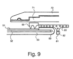
- Embodiment of the invention will now be described, by way of example only, with reference to the accompanying Drawings in which:
- Figure 1 shows a first embodiment of an installed pipe connector according to the present invention in part sectional side elevation;
- Figure 2 shows, in part sectional side elevation, a first hollow, tubular enclosure for use in a pipe connector according to the invention;
- Figure 3 shows, in part sectional side elevation, a second hollow, tubular enclosure for use in a pipe connector of the invention;
- Figure 4 shows an installed electrofusion coupler component, in part sectional side elevation, the coupler having projected terminals to provide electrical continuity across the joint;
- Figure 5 shows the coupler of Figure 4, again in part sectional side elevation, electrically connected to adjacent segments of a mechanical gripping means;
- Figure 6 shows a further embodiment of a pipe connector according to the invention, in part sectional side elevation, wherein the inner thermoplastic layer of the composite pipe has been turned over and lies on top of the reinforcing layer;
- Figure 7 shows a still further embodiment of a pipe connector according to the invention, in part sectional side elevation, wherein the inner thermoplastic layer of the composite pipe has been turned over in order to lie on top of the reinforcing layer and the mechanical gripping means is provided with teeth which pierce the outer protective layer of the composite pipe; and
- Figures 8 and 9 show variations on the pipe connector of Figure 7, wherein the tubular enclosure is formed from an expanded cross-linked polymeric material.
-
- Referring now to Figure 1, the pipe connector illustrated generally at 1 comprises a tubular enclosure body 2, having
annular recesses rings 6, segmented mechanical gripper rings 7, and anelectrofusion coupler 8. - In order to be received in the pipe connector, the ends of the
pipes 9, 10 have been cut back in order to expose sections of the inner thermoplastic layers 11, 12 and the reinforcinglayers - As illustrated, the pipe connector is pre-assembled, and then placed over the pipe ends. The dimensions of the tubular enclosure are such that, when the ends of the
pipes 9, 10 are pushed into thepipe connector 1 the enclosure 2 presses the sealing rings 6 into sealing engagement with the outer surfaces of the pipe outerprotective layers teeth 17 of the gripper rings 7 press into themetal reinforcing layers - The connection is completed by energising the
electrofusion coil 18 of theelectrofusion coupler 8 in order to fuse the adjacent thermoplastic material, and the outer surfaces of the inner thermoplastic layers 11 and 12, to make a fusion bond. - The axial strength of the tubular enclosure body 2 is greater than that of the
electrofusion coupler 8 in order to shift any tensile stresses away from the electrofusion bond. - It can readily be seen that gases and liquids from the interior of the pipe are prevented from reaching the reinforcing layer by the sealing action of the
fusion coupler 8, which of course also adds to the mechanical strength of the joint. Theconnector 1 directly grips onto the reinforcinglayers recesses 4, by means of the sealing rings 6 which are pressed firmly against the outer surfaces of the outerprotective layers - Figure 2 shows one embodiment of a hollow, tubular
enclosure body member 20, which comprises twosections fit connection 23. - In use, the electrofusion means is first installed, and then the
sections - A further embodiment of a hollow, tubular enclosure is shown in Figure 3, where means is provided for increasing the constraining force applied to the mechanical gripping means and sealing means by the hollow, tubular enclosure. In this embodiment, the enclosure body 30 is provided with
depressions such compression members compression members compression members projections compression members recesses compression members depression 33. - In other embodiments, the ramp surfaces 36, 37 of the enclosure body 30 could be provided with one or more axial slits which may assist radial deformation under the wedging action of the
conical compression members conical compression members - In Figure 3 the
recesses 4a are shown with frusto-conicalinner surfaces 4b which co-operate with frusto-conical surfaces on the gripping segments (not shown) to improve axial strength. - In Figure 4 there is illustrated a fusion coupler component of a pipe connector according to the invention, which is adapted to carry electrical continuity across the pipe connection. The
fusion coupler 40 comprises anelectrofusion coil 41 which is embedded in a layer of thermoplasticpolymeric material 42, for example, polyethylene. At each end of the coil there is provided a terminal 43, 44 which projects naturally outwards into the space occupied by the segmented gripping ring (not shown). - In use, the electrofusion coupler is first energised in order to fuse the coupler to the inner thermoplastic layers 45, 46 of the pipes to be joined. In the next stage, as shown in Figure 5, the segmented gripper rings are installed, with the
terminals sockets gripper ring segments metal layers segments fusion coil 41. - Figures 6, 7, 8 and 9 show further embodiments of pipe connections according to the invention, in.which the
pipe 50 to be joined is first prepared by cutting back the outerprotective layer 51 and themetal reinforcing layer 52, and folding back thethermoplastic layer 53 over themetal reinforcing layer 52. In Figure 6, the folding back of theinner thermoplastic layer 53 still leaves exposed asection 54 of the metal reinforcing layer for connection with thesegmented gripper ring 55. Theelectrofusion coupler 56 is disposed over the folded backsection 57 of theinner thermoplastic layer 53 and is fused thereto as previously described. - In the embodiment of Figure 7, the
inner thermoplastic layer 53 is folded over themetal reinforcing layer 52 until it abuts the end of the outerprotective layer 51. In this case thesegmented gripper ring 58 is provided withsharp teeth 59, which are pressed by the constraining force of theenclosure body 60 through the outerprotective layer 51 and into engagement with themetal reinforcing layer 52. This results in a slightly more compact structure than that shown in Figure 6. - Figure 8 shows a pipe connection similar to that of Figure 7, but wherein the hollow,
tubular enclosure 70 is formed from a pre-stressed, expanded polymeric material, for example, cross-linked polyethylene (PEX), which is first diametrically enlarged mechanically and supported on a splitcore supporting device 71. Theenclosure 70 andcore 71 are positioned over thegripper ring 58 andelectrofusion coupler 56 and then thecore 71 is removed. After removal of the core 71 theenclosure 70 shrinks with great force, and drives theteeth 59 of thegripper ring 58 through the outerprotective layer 51 of the pipe and into engagement with the reinforcinglayer 52. - Figure 9 shows a pipe connector similar to that of Figure 8, but wherein the
electrofusion coupler 80 is T-shaped in cross-section, and where in theextension 81 is also provided with anelectrofusion element 82 to fuse to thebent section 83 of the folded backthermoplastic layer 53 to lengthen the bond line and improve the seal.
Claims (26)
- A joint between an end of a pipe (9,10) and a connector (1), wherein the pipe comprises a multilayer composite pipe having at least one reinforcing layer, or layer of high axial strength (13,14), at least one inner thermoplastic layer (11,12), and at least one outer protective layer (15,16), and wherein the connector comprises:the fusion means and mechanical gripping means being disposed within the enclosure and the enclosure being adapted, in use, to apply a constraining force to the mechanical gripping means,(i) a hollow, tubular enclosure (2) adapted to receive the pipe;(ii) fusion means (8) adapted to make a fusion connection with the inner thermoplastic layer of the pipe; and(iii) mechanical gripping means (7) adapted to grip the reinforcing layer or high axial strength layer of the pipe;
characterised in that the thermoplastic layer extends beyond the end of the protective layer; in that the fusion means and mechanical gripping means are axially spaced within the connector; and in that the axial strength of the joint is provided more by the mechanical gripping means than said fusion connection. - A joint as claimed in claim 1, wherein the connector further comprises sealing means (6) disposed within the enclosure and adapted to form an environmental seal with the outer protective layer (15,16) of the pipe, the enclosure being adapted, in use, to apply a constraining force to the sealing means; and, preferably, in which the fusion means, mechanical gripping means and sealing means are disposed axially spaced from one another such that the sealing means is nearest to the end of the tubular enclosure, followed by the mechanical gripping means, and then the fusion means.
- A joint according to claim 1 or 2, in which the tubular enclosure comprises two or more co-operating hollow members (21,22), preferably the hollow members being threaded, in order that they can be screwed together, or having co-operating annular projections or depressions enabling them to be a snap-fit together.
- A joint according to claim 3, in which the action of screwing or pushing the component members of the tubular enclosure together acts to apply, or to increase, the constraining force on the gripping means and, optionally, the sealing means, when present.
- A joint according to claim 3 or 4, in which component members (30,34,35) of the tubular enclosure have co-operating conical surfaces (36,37) which are forced together in a ramp or wedging action in order to apply radially inwardly directed forces on the mechanical gripping means and, optionally, the sealing means, when present.
- A joint according to any of the preceding claims,
in which the hollow, tubular enclosure comprises a composite construction, with plastics and reinforcement layers; or
in which the fusion means comprises an electrofusion means (8) comprising an electrical conductor element (18) located adjacent to, or embedded in, a layer of fusible thermoplastic polymeric material, preferably polyethylene. - A joint according to any of the preceding claims, in which the mechanical gripping means comprises a series of two or more segments which are circumferentially disposed around the connector and are provided with teeth (17), or with roughened surfaces which are capable, in use, of contacting and gripping the reinforcing layer of the composite pipe; and, preferably, in which the teeth of the toothed segments (58,59) are sufficiently sharp to be able to penetrate the outer protective layer of the composite pipe in order to grip the reinforcing layer.
- A joint according to any of claims 1 to 6, in which the mechanical gripping means comprises a ring, or a series of arcuate segments, provided with helical threads which can be screwed onto the reinforcing layer of the pipe.
- A joint according to any of the preceding claims, in which the sealing means comprises one or more sealing rings, preferably O-rings (6), which are located in one or more recesses in the inner surface of the tubular enclosure; and, preferably, in which the sizes of the or each O-ring and the or each recess in the enclosure are arranged to be such that, in use, the enclosure applies a constraining force on the O-ring or rings in order to force it/them into sealing contact with the outer surface of the outer protective layer of the composite pipe.
- A joint according to any of claims 1 to 8, in which the sealing means comprises an adhesive sealing material; and preferably the sealing material comprises a mastic, an adhesive elastomeric sealant, or a hot melt adhesive.
- A joint according to any of the preceding claims, in which the connector is provided as two or more separate components which are individually installed.
- A joint as claimed in any preceding claim, in which said thermoplastic layer and reinforcing layer, or layer of high axial strength, are integrated in a single layer.
- A joint according to any of claims 1 to 11, which is adapted to provide electrical continuity across the connection.
- A joint according to any of claims 1 and 5,
in which the fusion means comprises an electrofusion means (8) comprising an electrical conductor element (18) located adjacent to, or embedded in, a layer of fusible thermoplastic polymeric material, preferably polyethylene; and
which is adapted to provide electrical continuity across the connection; and
in which the reinforcing layer comprises metal and wherein, in use, electrical continuity is provided by connecting one end of the electrofusion coil, either before or after fusion, to the end of the metal of the reinforcing layer. - A joint according to claim 14, in which the electrofusion coil is provided with terminals (43,44) which are connected, in use, either directly, or through the mechanical gripping means (49,50), to the reinforcing metal layers; and/or
in which the ends of the electrofusion coil are each provided with a terminal (43,44), one of which is received in a socket (47,48) in an adjacent segment of the segmented mechanical gripping means. - A joint according to claim 13, in which electrical continuity is provided via a conductive material of the tubular enclosure.
- A method of forming a connection to a multi-layer composite pipe (9,10), the pipe comprising at least one reinforcing layer, or layer of high axial strength (13,14), at least one inner thermoplastic layer (11,12) and at least one outer protective layer (15,16), wherein at least the outer protective layer of the composite pipe is cut back in order that circumferential surfaces of the inner thermoplastic layer, and the reinforcing layer, or high axial strength layer, are exposed for connection by a connector (1) comprising:grip the reinforcing layer of the pipe; the fusion means and mechanical gripping means being disposed within the enclosure and the enclosure being adapted, in use, to apply a constraining force to the mechanical gripping means, the axial strength of the joint being provided more by the mechanical gripping means than said fusion connection.(i) a hollow, tubular enclosure (2) adapted to receive the pipe;(ii) fusion means (8) adapted to make a fusion connection with the inner thermoplastic layer of the pipe; and,(iii) axially spaced from the fusion means, mechanical gripping means (7) adapted to
- A method as claimed in claim 17 in which said thermoplastic layer and said reinforcing layer, or layer of high axial strength are separate, said reinforcing layer, or layer of high axial strength, also being cut back; and, preferably, wherein the lengths of the inner thermoplastic layer and the reinforcing layer, or high axial strength layer, exposed for connection are from 20 to 200% of OD, where OD is the outer diameter of the pipe.
- A method according to claim 18, in which, in preparing the pipe for connection, an upstanding projection at the cut-back edge of the reinforcing layer is provided; or
in which a section of the inner thermoplastic layer is turned over so that it lies on top of and overlaps the reinforcing layer for a short distance at the end of the pipe. - A method as claimed in any of claims 17 to 19, in which the tubular enclosure is formed from an expanded cross-linked polymeric material which is "held-out" on a removable core, which core is removed after the fusion means, mechanical gripping means and sealing means (when present) have been positioned on the pipe such that the tubular enclosure contracts radially to engage the gripping means and sealing means, when present, with the reinforcing layer, or layer of high axial strength, and protective layer respectively.
- A joint between an end of a pipe (9,10) and a connector (1), wherein the pipe comprises a multilayer composite pipe having at least three distinct layers including a reinforcing layer, or layer of high axial strength (13,14), an inner thermoplastic layer (11,12), and an outer protective layer (15,16), and wherein the connector comprises:the fusion means and mechanical gripping means being disposed within the enclosure and the enclosure being adapted, in use, to apply a constraining force to the mechanical gripping means, and wherein the thermoplastic layer extends beyond the end of the reinforcing layer, or layer of high axial strength.(i) a hollow, tubular enclosure (2) adapted to receive the pipe;(ii) fusion means (8) adapted to make a fusion connection with the inner thermoplastic layer of the pipe; and(iii) axially spaced from the fusion means, mechanical gripping means (7) adapted to grip the reinforcing layer or high axial strength layer of the pipe;
- A joint as claimed in claim 21 wherein the reinforcing layer, or layer of high axial strength, does not extend beyond the end of the protective layer and said mechanical gripping means grips the reinforcing layer, or layer of high axial strength, through the protective layer.
- Use of a connector comprising a hollow tubular enclosure in which is disposed fusion means (8) and, axially spaced therefrom, mechanical gripping means (7), to join a multi-layer composite pipe having at least three distinct layers including a reinforcing layer, or layer of high axial strength (13,14), an inner thermoplastic layer (11,12), and at least one outer protective layer (15,16), the fusion means being adapted to make a fusion connection with the inner thermoplastic layer of the pipe, and the mechanical gripping means being adapted to grip the reinforcing layer or high axial strength layer of the pipe, and wherein the enclosure is adapted, in use, to apply a constraining force to the mechanical gripping means, the protective layer and reinforcing layer, or layer of high axial strength, being cut back to expose at least the thermoplastic layer for said fusion connection.
- Use as claimed in claim 23, wherein said protective layer is further cut back to expose the reinforcing layer, or layer of high axial strength.
- A method of forming a connection to a multi-layer composite pipe (9,10), the pipe comprising at least three distinct layers including a reinforcing layer, or layer of high axial strength (13,14), an inner thermoplastic layer (11,12) and an outer protective layer (15,16), wherein the outer protective layer of the composite pipe and the reinforcing layer, or high axial strength layer, are cut back in order that circumferential surfaces of the inner thermoplastic layer are exposed for connection by a connector (1) comprising:the fusion means and mechanical gripping means being disposed within the enclosure and the enclosure being adapted, in use, to apply a constraining force to the mechanical gripping means.(i) a hollow, tubular enclosure (2) adapted to receive the pipe;(ii) fusion means (8) adapted to make a fusion connection with the inner thermoplastic layer of the pipe; and,(iii) axially spaced from the fusion means, mechanical gripping means (7) adapted to grip the reinforcing layer of the pipe;
- A method as claimed in claim 25 in which the outer protective layer is cut back to expose the reinforcing layer or layer of high axial strength to permit the mechanical gripping means to grip that layer without the necessity to penetrate the protective layer.
Applications Claiming Priority (3)
| Application Number | Priority Date | Filing Date | Title |
|---|---|---|---|
| GB9624102A GB2319576B (en) | 1996-11-20 | 1996-11-20 | Pipe connector |
| GB9624102 | 1996-11-20 | ||
| PCT/GB1997/003110 WO1998022744A1 (en) | 1996-11-20 | 1997-11-20 | Pipe connector |
Publications (2)
| Publication Number | Publication Date |
|---|---|
| EP0939874A1 EP0939874A1 (en) | 1999-09-08 |
| EP0939874B1 true EP0939874B1 (en) | 2003-01-15 |
Family
ID=10803213
Family Applications (1)
| Application Number | Title | Priority Date | Filing Date |
|---|---|---|---|
| EP97913293A Expired - Lifetime EP0939874B1 (en) | 1996-11-20 | 1997-11-20 | Pipe connector |
Country Status (11)
| Country | Link |
|---|---|
| US (1) | US6375226B1 (en) |
| EP (1) | EP0939874B1 (en) |
| JP (1) | JP3833715B2 (en) |
| AT (1) | ATE231228T1 (en) |
| AU (1) | AU729848B2 (en) |
| CA (1) | CA2272059C (en) |
| DE (1) | DE69718504T2 (en) |
| ES (1) | ES2189955T3 (en) |
| GB (1) | GB2319576B (en) |
| RU (1) | RU2187034C2 (en) |
| WO (1) | WO1998022744A1 (en) |
Families Citing this family (37)
| Publication number | Priority date | Publication date | Assignee | Title |
|---|---|---|---|---|
| NL1009169C2 (en) * | 1998-05-14 | 1999-11-16 | Polva Pipelife Bv | Welded sleeve connection for high pressure pipe. |
| US6293311B1 (en) | 1998-05-22 | 2001-09-25 | Pmd Holdings Corp. | Multilayer composite pipe fluid conduit system using multilayer composite pipe and method of making the composite |
| FR2786429B1 (en) | 1998-11-27 | 2001-01-19 | Seva | METHOD FOR CONNECTING TWO TUBES OF REINFORCED THERMOPLASTIC MATERIAL |
| US6892753B2 (en) * | 2001-06-06 | 2005-05-17 | Perfection Corporation | Structure for converting a mechanical joint to a fusion joint |
| ITMI20012257A1 (en) * | 2001-10-26 | 2003-04-26 | Nupi S P A | MULTILAYER TUBE WITH WELDABLE END HEAD TO HEAD AND WELDING METHOD OF A MULTILAYER TUBE |
| DE10225370A1 (en) * | 2002-06-06 | 2003-12-18 | Georg Fischer Wavin Ag Subinge | Electric welding sleeve |
| US7534321B2 (en) * | 2003-01-29 | 2009-05-19 | Ncf Industries, Inc. | System for joining sections of composite reinforced line pipe |
| US20060016552A1 (en) | 2004-07-20 | 2006-01-26 | George Fischer Sloane, Inc. | Electrofusion pipe-fitting joining system and method utilizing conductive polymeric resin |
| FR2876773B1 (en) * | 2004-10-19 | 2007-02-02 | Saipem S A Sa | DRIVING HAVING AN INTERNAL SHIRT, IN PARTICULAR UNDERWATER DRIVING |
| GB2421469B (en) * | 2004-12-23 | 2010-03-03 | Uponor Innovation Ab | Plastic pipe |
| US20060202471A1 (en) * | 2005-03-07 | 2006-09-14 | Weisbond Bradley K | Electro-fusion joining system for thermoplastic piping systems |
| GB2425337A (en) * | 2005-04-22 | 2006-10-25 | Uponor Innovation Ab | Electrofusion fitting to seal barrier layer of composite pipe |
| JP4883438B2 (en) * | 2005-08-04 | 2012-02-22 | 三井金属エンジニアリング株式会社 | Plastic pipe joint structure |
| AU2014201808B2 (en) * | 2006-04-12 | 2016-02-04 | Orrcon Operations Pty Ltd | Pipe and pipe joining method |
| DE102007014049B3 (en) * | 2007-03-21 | 2008-12-04 | Friatec Ag | Compensation element for connecting components |
| GB0712969D0 (en) * | 2007-07-05 | 2007-08-15 | Uponor Ltd | Electrofusion fitting for a composite pipe |
| GB2451081B (en) * | 2007-07-17 | 2009-09-09 | Uponor Innovation Ab | Electrofusion fitting |
| IL188826A0 (en) * | 2008-01-16 | 2008-11-03 | Noam Kahani | Reinforced irrigation pipe |
| US20090273184A1 (en) * | 2008-04-30 | 2009-11-05 | Michael Wright | Self restrained joint for ductile iron pipe and fittings |
| US8424924B2 (en) | 2008-09-19 | 2013-04-23 | Tas Acquisition Co., Llc | Electromagnetic bond welding of thermoplastic pipe distribution systems |
| AR071492A1 (en) | 2009-04-22 | 2010-06-23 | Rukavina Mikusic Juan | METHOD FOR THE THERMAL COATING OF HIGH THICKNESS OF JOINTS THROUGH ELECTROFUSION IN DUCTS USED IN DRIVING FLUIDS BUILT WITH STEEL PIPES COVERED EXTERNALLY WITH POLYOLEFINS |
| GB2485350A (en) * | 2010-11-08 | 2012-05-16 | Coupling Solutions Llc | Pipe coupling |
| AU2012273037B2 (en) * | 2011-06-21 | 2016-09-01 | United Pipeline Systems, Inc. | Connections of lined pipe |
| CA3040163C (en) | 2012-02-17 | 2021-02-16 | Core Linepipe Inc. | Pipe electro-fusion assembly |
| US9285063B2 (en) | 2013-06-22 | 2016-03-15 | Mark L. Jones | Connection fitting for connecting thermoplastic pipes |
| US9719622B2 (en) | 2013-07-08 | 2017-08-01 | Georg Fischer Harvel Llc | Electrofusion fittings and methods |
| CA2828855C (en) | 2013-09-27 | 2020-06-09 | G.B.D. Corp. | Method and apparatus for connecting pipes |
| CA2829041C (en) | 2013-09-27 | 2020-06-09 | G.B.D. Corp. | Pipe sealing tool and methods for use |
| CA2829075C (en) | 2013-09-27 | 2020-09-01 | G.B.D. Corp. | Pipe joining material for connecting pipes |
| CA2829002C (en) | 2013-09-27 | 2020-06-09 | G.B.D. Corp. | Pipe cutting tool and methods for use |
| EP2902172B1 (en) | 2014-01-30 | 2018-03-07 | PLASSON Ltd | Electrofusion coupling member and process of manufacturing electrofusion coupling member |
| IL237008B (en) | 2014-01-30 | 2020-03-31 | Plasson Ltd | Electrofusion coupler composition |
| GB2537897B (en) * | 2015-04-30 | 2018-12-12 | Magma Global Ltd | Fluid conduit joining method |
| JP7240752B2 (en) * | 2018-07-23 | 2023-03-16 | 株式会社アクシス | Coupling device, joint structure, and joint structure manufacturing method |
| TW202122704A (en) * | 2019-09-30 | 2021-06-16 | 日商積水化學工業股份有限公司 | Electrically fusion bonded joint |
| US11725755B2 (en) | 2020-10-29 | 2023-08-15 | United Pipeline Systems, Inc. | Connections of lined pipe |
| CN114183616A (en) * | 2021-12-16 | 2022-03-15 | 华创天元实业发展有限责任公司 | Pipeline connecting device and method |
Family Cites Families (28)
| Publication number | Priority date | Publication date | Assignee | Title |
|---|---|---|---|---|
| GB599993A (en) * | 1945-09-27 | 1948-03-25 | Edward Charles Carling | Improvements in flexible-hose couplings |
| GB588748A (en) * | 1945-03-06 | 1947-06-02 | Tecalemit Ltd | Improvements in liquid or lubricant distributing means |
| FR1418758A (en) * | 1962-03-01 | 1965-11-26 | Inst Francais Du Petrole | Fitting for reinforced flexible tube |
| GB1007859A (en) * | 1962-12-14 | 1965-10-22 | Superflexit | End fittings for conduits or hoses |
| NL7013178A (en) * | 1970-09-07 | 1972-03-09 | ||
| GB1480061A (en) * | 1973-04-06 | 1977-07-20 | English Clays Lovering Pochin | Joints between two metallic pipe members |
| FR2229914B1 (en) * | 1973-05-14 | 1976-04-23 | Inst Francais Du Petrole | |
| DE3013796A1 (en) * | 1980-04-10 | 1981-10-15 | G + H Montage Gmbh, 6700 Ludwigshafen | THERMAL INSULATED TUBE |
| US4353581A (en) * | 1980-11-28 | 1982-10-12 | The Goodyear Tire & Rubber Company | Hose coupling |
| DE3306832A1 (en) * | 1983-02-26 | 1984-08-30 | Friedrich Theysohn GmbH, 3320 Salzgitter | Device for connecting two pipes consisting of plastic |
| CH671444A5 (en) * | 1986-06-25 | 1989-08-31 | Fischer Ag Georg | |
| JPH02305517A (en) * | 1989-05-19 | 1990-12-19 | Matsushita Electric Ind Co Ltd | Rice boiler |
| NL8902950A (en) | 1989-11-29 | 1991-06-17 | Wavin Bv | PLASTIC TUBE WITH WALL BUILT UP FROM A PLASTIC FILLER LAYER. |
| GB2244179B (en) * | 1990-05-15 | 1994-09-07 | Senior Tift Ltd | Hose assemblies |
| JPH04171392A (en) * | 1990-11-02 | 1992-06-18 | Osaka Gas Co Ltd | Electrically fused pipe joint |
| JPH04258594A (en) * | 1991-02-14 | 1992-09-14 | Sekisui Chem Co Ltd | Electric fusion joint |
| CA2085886A1 (en) * | 1991-04-19 | 1992-10-20 | Kenji Mizukawa | Pipe joint member |
| NO175550C (en) | 1991-05-31 | 1997-05-02 | Compipe As | Method of preparing laminate tubes |
| JP3152712B2 (en) * | 1992-01-23 | 2001-04-03 | 積水化学工業株式会社 | Electric fusion joint |
| EP0612953A1 (en) * | 1993-02-22 | 1994-08-31 | Streng Plastic AG | Connector for tubular plastic parts |
| GB9314971D0 (en) * | 1993-07-20 | 1993-09-01 | British Gas Plc | A method of joining reinforced thermoplastic pipes |
| GB9414428D0 (en) | 1994-07-16 | 1994-09-07 | Sec Dep For Foreign And Common | Improvements in or relating to cryopreservation |
| JPH08135875A (en) * | 1994-11-10 | 1996-05-31 | Hitachi Metals Ltd | Electro-fusion coupling |
| DE4444097C2 (en) | 1994-12-10 | 1997-02-27 | Unicor Rohrsysteme Gmbh | Device for connecting at least two plastic-metal composite pipes by welding |
| GB2297137B (en) * | 1995-01-18 | 1999-02-03 | Uponor Ltd | Plastics pipe |
| EP0736719B1 (en) | 1995-04-03 | 1999-07-14 | Uponor B.V. | Pipe connection and a method for its manufacture |
| GB2304163B (en) * | 1995-08-05 | 1999-03-17 | Uponor Ltd | Pipe joint and electrofusion coupling therefor |
| FI100130B (en) | 1995-12-12 | 1997-09-30 | Uponor Innovation Ab | Multilayer plastic pipe |
-
1996
- 1996-11-20 GB GB9624102A patent/GB2319576B/en not_active Expired - Fee Related
-
1997
- 1997-11-20 AT AT97913293T patent/ATE231228T1/en not_active IP Right Cessation
- 1997-11-20 WO PCT/GB1997/003110 patent/WO1998022744A1/en active IP Right Grant
- 1997-11-20 EP EP97913293A patent/EP0939874B1/en not_active Expired - Lifetime
- 1997-11-20 AU AU50596/98A patent/AU729848B2/en not_active Ceased
- 1997-11-20 ES ES97913293T patent/ES2189955T3/en not_active Expired - Lifetime
- 1997-11-20 JP JP52332098A patent/JP3833715B2/en not_active Expired - Fee Related
- 1997-11-20 US US09/308,419 patent/US6375226B1/en not_active Expired - Fee Related
- 1997-11-20 RU RU99113022/06A patent/RU2187034C2/en not_active IP Right Cessation
- 1997-11-20 DE DE69718504T patent/DE69718504T2/en not_active Expired - Lifetime
- 1997-11-20 CA CA002272059A patent/CA2272059C/en not_active Expired - Fee Related
Also Published As
| Publication number | Publication date |
|---|---|
| GB9624102D0 (en) | 1997-01-08 |
| CA2272059C (en) | 2008-02-12 |
| CA2272059A1 (en) | 1998-05-28 |
| RU2187034C2 (en) | 2002-08-10 |
| JP3833715B2 (en) | 2006-10-18 |
| AU729848B2 (en) | 2001-02-08 |
| US6375226B1 (en) | 2002-04-23 |
| AU5059698A (en) | 1998-06-10 |
| WO1998022744A1 (en) | 1998-05-28 |
| GB2319576A (en) | 1998-05-27 |
| ES2189955T3 (en) | 2003-07-16 |
| EP0939874A1 (en) | 1999-09-08 |
| JP2001505287A (en) | 2001-04-17 |
| ATE231228T1 (en) | 2003-02-15 |
| DE69718504D1 (en) | 2003-02-20 |
| GB2319576B (en) | 2001-02-07 |
| DE69718504T2 (en) | 2003-11-20 |
Similar Documents
| Publication | Publication Date | Title |
|---|---|---|
| EP0939874B1 (en) | Pipe connector | |
| US6149756A (en) | Method for joining plastic pipes, a joint ring used in the joining and a pipe joint provided with the method | |
| EP1078189A1 (en) | Multilayer composite pipe, fluid conduit system using multilayer composite pipe and method of making the composite pipe | |
| KR19990022204A (en) | Heat recoverable articles | |
| GB2325501A (en) | Heat fusion fitting | |
| EP1468219B1 (en) | Connection of internally lined pipelines | |
| EP0918619B1 (en) | Electrofusion fitting | |
| CA2776955C (en) | Heat-fusible gasket and method of manufacture | |
| US4514241A (en) | Reinsulation of pipe joints | |
| US20060182954A1 (en) | Joining metal and plastics surfaces | |
| EP1388703A1 (en) | Fitting for composite pipe | |
| GB2314597A (en) | Electrofusion fitting for a plastics pipe with gripping means | |
| JP2009204144A (en) | Connection method of hose and resin nipple for mouthpiece and hose mouthpiece connection structure | |
| WO2009148318A1 (en) | Coupling piece with flange, conduit system with at least one such coupling piece, method for connecting a conduit and a coupling piece, and connecting device | |
| GB2431135A (en) | Heated wire thermoplastic and elastomer bonding | |
| GB2340904A (en) | Method of forming fusion joint and fusion fitting for joint | |
| WO2023054699A1 (en) | Piping member and method for manufacturing piping member | |
| EP0736719B1 (en) | Pipe connection and a method for its manufacture | |
| CN1242828A (en) | Pipe connector | |
| GB2333817A (en) | Fusion bonding of a pipe to a pipe, sleeve or fitting | |
| JPH05141582A (en) | Pipe joint | |
| JPH10185067A (en) | Electric fusion joint | |
| JP2011241884A (en) | Pipe connection structure and pipe connection method | |
| KR20040042409A (en) | Connecting pipe embeded with heating coil for plastic pipes |
Legal Events
| Date | Code | Title | Description |
|---|---|---|---|
| PUAI | Public reference made under article 153(3) epc to a published international application that has entered the european phase |
Free format text: ORIGINAL CODE: 0009012 |
|
| 17P | Request for examination filed |
Effective date: 19990528 |
|
| AK | Designated contracting states |
Kind code of ref document: A1 Designated state(s): AT BE CH DE DK ES FI FR GB GR IE IT LI LU MC NL PT SE |
|
| RAP1 | Party data changed (applicant data changed or rights of an application transferred) |
Owner name: UPONOR INNOVATION AB |
|
| GRAG | Despatch of communication of intention to grant |
Free format text: ORIGINAL CODE: EPIDOS AGRA |
|
| 17Q | First examination report despatched |
Effective date: 20020220 |
|
| GRAG | Despatch of communication of intention to grant |
Free format text: ORIGINAL CODE: EPIDOS AGRA |
|
| GRAH | Despatch of communication of intention to grant a patent |
Free format text: ORIGINAL CODE: EPIDOS IGRA |
|
| GRAH | Despatch of communication of intention to grant a patent |
Free format text: ORIGINAL CODE: EPIDOS IGRA |
|
| GRAA | (expected) grant |
Free format text: ORIGINAL CODE: 0009210 |
|
| AK | Designated contracting states |
Kind code of ref document: B1 Designated state(s): AT BE CH DE DK ES FI FR GB GR IE IT LI LU MC NL PT SE |
|
| PG25 | Lapsed in a contracting state [announced via postgrant information from national office to epo] |
Ref country code: NL Free format text: LAPSE BECAUSE OF FAILURE TO SUBMIT A TRANSLATION OF THE DESCRIPTION OR TO PAY THE FEE WITHIN THE PRESCRIBED TIME-LIMIT Effective date: 20030115 Ref country code: GR Free format text: LAPSE BECAUSE OF FAILURE TO SUBMIT A TRANSLATION OF THE DESCRIPTION OR TO PAY THE FEE WITHIN THE PRESCRIBED TIME-LIMIT Effective date: 20030115 Ref country code: FI Free format text: LAPSE BECAUSE OF FAILURE TO SUBMIT A TRANSLATION OF THE DESCRIPTION OR TO PAY THE FEE WITHIN THE PRESCRIBED TIME-LIMIT Effective date: 20030115 Ref country code: BE Free format text: LAPSE BECAUSE OF FAILURE TO SUBMIT A TRANSLATION OF THE DESCRIPTION OR TO PAY THE FEE WITHIN THE PRESCRIBED TIME-LIMIT Effective date: 20030115 Ref country code: AT Free format text: LAPSE BECAUSE OF FAILURE TO SUBMIT A TRANSLATION OF THE DESCRIPTION OR TO PAY THE FEE WITHIN THE PRESCRIBED TIME-LIMIT Effective date: 20030115 |
|
| REG | Reference to a national code |
Ref country code: GB Ref legal event code: FG4D Ref country code: CH Ref legal event code: EP |
|
| REG | Reference to a national code |
Ref country code: IE Ref legal event code: FG4D |
|
| REF | Corresponds to: |
Ref document number: 69718504 Country of ref document: DE Date of ref document: 20030220 Kind code of ref document: P |
|
| REG | Reference to a national code |
Ref country code: CH Ref legal event code: NV Representative=s name: TROESCH SCHEIDEGGER WERNER AG |
|
| PG25 | Lapsed in a contracting state [announced via postgrant information from national office to epo] |
Ref country code: SE Free format text: LAPSE BECAUSE OF FAILURE TO SUBMIT A TRANSLATION OF THE DESCRIPTION OR TO PAY THE FEE WITHIN THE PRESCRIBED TIME-LIMIT Effective date: 20030415 Ref country code: PT Free format text: LAPSE BECAUSE OF FAILURE TO SUBMIT A TRANSLATION OF THE DESCRIPTION OR TO PAY THE FEE WITHIN THE PRESCRIBED TIME-LIMIT Effective date: 20030415 Ref country code: DK Free format text: LAPSE BECAUSE OF FAILURE TO SUBMIT A TRANSLATION OF THE DESCRIPTION OR TO PAY THE FEE WITHIN THE PRESCRIBED TIME-LIMIT Effective date: 20030415 |
|
| ET | Fr: translation filed | ||
| NLV1 | Nl: lapsed or annulled due to failure to fulfill the requirements of art. 29p and 29m of the patents act | ||
| REG | Reference to a national code |
Ref country code: ES Ref legal event code: FG2A Ref document number: 2189955 Country of ref document: ES Kind code of ref document: T3 |
|
| PG25 | Lapsed in a contracting state [announced via postgrant information from national office to epo] |
Ref country code: LU Free format text: LAPSE BECAUSE OF NON-PAYMENT OF DUE FEES Effective date: 20031120 Ref country code: IE Free format text: LAPSE BECAUSE OF NON-PAYMENT OF DUE FEES Effective date: 20031120 Ref country code: GB Free format text: LAPSE BECAUSE OF NON-PAYMENT OF DUE FEES Effective date: 20031120 |
|
| PLBE | No opposition filed within time limit |
Free format text: ORIGINAL CODE: 0009261 |
|
| STAA | Information on the status of an ep patent application or granted ep patent |
Free format text: STATUS: NO OPPOSITION FILED WITHIN TIME LIMIT |
|
| PG25 | Lapsed in a contracting state [announced via postgrant information from national office to epo] |
Ref country code: MC Free format text: LAPSE BECAUSE OF NON-PAYMENT OF DUE FEES Effective date: 20031130 |
|
| 26N | No opposition filed |
Effective date: 20031016 |
|
| GBPC | Gb: european patent ceased through non-payment of renewal fee |
Effective date: 20031120 |
|
| REG | Reference to a national code |
Ref country code: IE Ref legal event code: MM4A |
|
| PGFP | Annual fee paid to national office [announced via postgrant information from national office to epo] |
Ref country code: CH Payment date: 20081024 Year of fee payment: 12 |
|
| PGFP | Annual fee paid to national office [announced via postgrant information from national office to epo] |
Ref country code: IT Payment date: 20081020 Year of fee payment: 12 |
|
| REG | Reference to a national code |
Ref country code: CH Ref legal event code: PL |
|
| PG25 | Lapsed in a contracting state [announced via postgrant information from national office to epo] |
Ref country code: LI Free format text: LAPSE BECAUSE OF NON-PAYMENT OF DUE FEES Effective date: 20091130 Ref country code: CH Free format text: LAPSE BECAUSE OF NON-PAYMENT OF DUE FEES Effective date: 20091130 |
|
| PGFP | Annual fee paid to national office [announced via postgrant information from national office to epo] |
Ref country code: DE Payment date: 20101119 Year of fee payment: 14 |
|
| PG25 | Lapsed in a contracting state [announced via postgrant information from national office to epo] |
Ref country code: IT Free format text: LAPSE BECAUSE OF NON-PAYMENT OF DUE FEES Effective date: 20091120 |
|
| PGFP | Annual fee paid to national office [announced via postgrant information from national office to epo] |
Ref country code: ES Payment date: 20101126 Year of fee payment: 14 |
|
| PGFP | Annual fee paid to national office [announced via postgrant information from national office to epo] |
Ref country code: FR Payment date: 20111130 Year of fee payment: 15 |
|
| REG | Reference to a national code |
Ref country code: ES Ref legal event code: FD2A Effective date: 20130603 |
|
| PG25 | Lapsed in a contracting state [announced via postgrant information from national office to epo] |
Ref country code: ES Free format text: LAPSE BECAUSE OF NON-PAYMENT OF DUE FEES Effective date: 20111121 |
|
| REG | Reference to a national code |
Ref country code: FR Ref legal event code: ST Effective date: 20130731 |
|
| REG | Reference to a national code |
Ref country code: DE Ref legal event code: R119 Ref document number: 69718504 Country of ref document: DE Effective date: 20130601 |
|
| PG25 | Lapsed in a contracting state [announced via postgrant information from national office to epo] |
Ref country code: DE Free format text: LAPSE BECAUSE OF NON-PAYMENT OF DUE FEES Effective date: 20130601 |
|
| PG25 | Lapsed in a contracting state [announced via postgrant information from national office to epo] |
Ref country code: FR Free format text: LAPSE BECAUSE OF NON-PAYMENT OF DUE FEES Effective date: 20121130 |