EP0612953A1 - Connector for tubular plastic parts - Google Patents
Connector for tubular plastic parts Download PDFInfo
- Publication number
- EP0612953A1 EP0612953A1 EP19940810080 EP94810080A EP0612953A1 EP 0612953 A1 EP0612953 A1 EP 0612953A1 EP 19940810080 EP19940810080 EP 19940810080 EP 94810080 A EP94810080 A EP 94810080A EP 0612953 A1 EP0612953 A1 EP 0612953A1
- Authority
- EP
- European Patent Office
- Prior art keywords
- pipe
- connection
- pipes
- outer sleeve
- connecting sleeve
- Prior art date
- Legal status (The legal status is an assumption and is not a legal conclusion. Google has not performed a legal analysis and makes no representation as to the accuracy of the status listed.)
- Withdrawn
Links
Images

Classifications
-
- F—MECHANICAL ENGINEERING; LIGHTING; HEATING; WEAPONS; BLASTING
- F16—ENGINEERING ELEMENTS AND UNITS; GENERAL MEASURES FOR PRODUCING AND MAINTAINING EFFECTIVE FUNCTIONING OF MACHINES OR INSTALLATIONS; THERMAL INSULATION IN GENERAL
- F16L—PIPES; JOINTS OR FITTINGS FOR PIPES; SUPPORTS FOR PIPES, CABLES OR PROTECTIVE TUBING; MEANS FOR THERMAL INSULATION IN GENERAL
- F16L47/00—Connecting arrangements or other fittings specially adapted to be made of plastics or to be used with pipes made of plastics
- F16L47/02—Welded joints; Adhesive joints
- F16L47/03—Welded joints with an electrical resistance incorporated in the joint
-
- B—PERFORMING OPERATIONS; TRANSPORTING
- B29—WORKING OF PLASTICS; WORKING OF SUBSTANCES IN A PLASTIC STATE IN GENERAL
- B29C—SHAPING OR JOINING OF PLASTICS; SHAPING OF MATERIAL IN A PLASTIC STATE, NOT OTHERWISE PROVIDED FOR; AFTER-TREATMENT OF THE SHAPED PRODUCTS, e.g. REPAIRING
- B29C65/00—Joining or sealing of preformed parts, e.g. welding of plastics materials; Apparatus therefor
- B29C65/02—Joining or sealing of preformed parts, e.g. welding of plastics materials; Apparatus therefor by heating, with or without pressure
- B29C65/34—Joining or sealing of preformed parts, e.g. welding of plastics materials; Apparatus therefor by heating, with or without pressure using heated elements which remain in the joint, e.g. "verlorenes Schweisselement"
- B29C65/3404—Joining or sealing of preformed parts, e.g. welding of plastics materials; Apparatus therefor by heating, with or without pressure using heated elements which remain in the joint, e.g. "verlorenes Schweisselement" characterised by the type of heated elements which remain in the joint
- B29C65/342—Joining or sealing of preformed parts, e.g. welding of plastics materials; Apparatus therefor by heating, with or without pressure using heated elements which remain in the joint, e.g. "verlorenes Schweisselement" characterised by the type of heated elements which remain in the joint comprising at least a single wire, e.g. in the form of a winding
-
- B—PERFORMING OPERATIONS; TRANSPORTING
- B29—WORKING OF PLASTICS; WORKING OF SUBSTANCES IN A PLASTIC STATE IN GENERAL
- B29C—SHAPING OR JOINING OF PLASTICS; SHAPING OF MATERIAL IN A PLASTIC STATE, NOT OTHERWISE PROVIDED FOR; AFTER-TREATMENT OF THE SHAPED PRODUCTS, e.g. REPAIRING
- B29C65/00—Joining or sealing of preformed parts, e.g. welding of plastics materials; Apparatus therefor
- B29C65/48—Joining or sealing of preformed parts, e.g. welding of plastics materials; Apparatus therefor using adhesives, i.e. using supplementary joining material; solvent bonding
- B29C65/50—Joining or sealing of preformed parts, e.g. welding of plastics materials; Apparatus therefor using adhesives, i.e. using supplementary joining material; solvent bonding using adhesive tape, e.g. thermoplastic tape; using threads or the like
- B29C65/5042—Joining or sealing of preformed parts, e.g. welding of plastics materials; Apparatus therefor using adhesives, i.e. using supplementary joining material; solvent bonding using adhesive tape, e.g. thermoplastic tape; using threads or the like covering both elements to be joined
-
- B—PERFORMING OPERATIONS; TRANSPORTING
- B29—WORKING OF PLASTICS; WORKING OF SUBSTANCES IN A PLASTIC STATE IN GENERAL
- B29C—SHAPING OR JOINING OF PLASTICS; SHAPING OF MATERIAL IN A PLASTIC STATE, NOT OTHERWISE PROVIDED FOR; AFTER-TREATMENT OF THE SHAPED PRODUCTS, e.g. REPAIRING
- B29C66/00—General aspects of processes or apparatus for joining preformed parts
- B29C66/01—General aspects dealing with the joint area or with the area to be joined
- B29C66/05—Particular design of joint configurations
- B29C66/10—Particular design of joint configurations particular design of the joint cross-sections
- B29C66/12—Joint cross-sections combining only two joint-segments; Tongue and groove joints; Tenon and mortise joints; Stepped joint cross-sections
- B29C66/128—Stepped joint cross-sections
- B29C66/1282—Stepped joint cross-sections comprising at least one overlap joint-segment
-
- B—PERFORMING OPERATIONS; TRANSPORTING
- B29—WORKING OF PLASTICS; WORKING OF SUBSTANCES IN A PLASTIC STATE IN GENERAL
- B29C—SHAPING OR JOINING OF PLASTICS; SHAPING OF MATERIAL IN A PLASTIC STATE, NOT OTHERWISE PROVIDED FOR; AFTER-TREATMENT OF THE SHAPED PRODUCTS, e.g. REPAIRING
- B29C66/00—General aspects of processes or apparatus for joining preformed parts
- B29C66/01—General aspects dealing with the joint area or with the area to be joined
- B29C66/05—Particular design of joint configurations
- B29C66/10—Particular design of joint configurations particular design of the joint cross-sections
- B29C66/12—Joint cross-sections combining only two joint-segments; Tongue and groove joints; Tenon and mortise joints; Stepped joint cross-sections
- B29C66/128—Stepped joint cross-sections
- B29C66/1284—Stepped joint cross-sections comprising at least one butt joint-segment
- B29C66/12841—Stepped joint cross-sections comprising at least one butt joint-segment comprising at least two butt joint-segments
-
- B—PERFORMING OPERATIONS; TRANSPORTING
- B29—WORKING OF PLASTICS; WORKING OF SUBSTANCES IN A PLASTIC STATE IN GENERAL
- B29C—SHAPING OR JOINING OF PLASTICS; SHAPING OF MATERIAL IN A PLASTIC STATE, NOT OTHERWISE PROVIDED FOR; AFTER-TREATMENT OF THE SHAPED PRODUCTS, e.g. REPAIRING
- B29C66/00—General aspects of processes or apparatus for joining preformed parts
- B29C66/50—General aspects of joining tubular articles; General aspects of joining long products, i.e. bars or profiled elements; General aspects of joining single elements to tubular articles, hollow articles or bars; General aspects of joining several hollow-preforms to form hollow or tubular articles
- B29C66/51—Joining tubular articles, profiled elements or bars; Joining single elements to tubular articles, hollow articles or bars; Joining several hollow-preforms to form hollow or tubular articles
- B29C66/52—Joining tubular articles, bars or profiled elements
- B29C66/522—Joining tubular articles
- B29C66/5221—Joining tubular articles for forming coaxial connections, i.e. the tubular articles to be joined forming a zero angle relative to each other
-
- B—PERFORMING OPERATIONS; TRANSPORTING
- B29—WORKING OF PLASTICS; WORKING OF SUBSTANCES IN A PLASTIC STATE IN GENERAL
- B29C—SHAPING OR JOINING OF PLASTICS; SHAPING OF MATERIAL IN A PLASTIC STATE, NOT OTHERWISE PROVIDED FOR; AFTER-TREATMENT OF THE SHAPED PRODUCTS, e.g. REPAIRING
- B29C66/00—General aspects of processes or apparatus for joining preformed parts
- B29C66/50—General aspects of joining tubular articles; General aspects of joining long products, i.e. bars or profiled elements; General aspects of joining single elements to tubular articles, hollow articles or bars; General aspects of joining several hollow-preforms to form hollow or tubular articles
- B29C66/51—Joining tubular articles, profiled elements or bars; Joining single elements to tubular articles, hollow articles or bars; Joining several hollow-preforms to form hollow or tubular articles
- B29C66/52—Joining tubular articles, bars or profiled elements
- B29C66/522—Joining tubular articles
- B29C66/5229—Joining tubular articles involving the use of a socket
- B29C66/52298—Joining tubular articles involving the use of a socket said socket being composed by several elements
-
- B—PERFORMING OPERATIONS; TRANSPORTING
- B29—WORKING OF PLASTICS; WORKING OF SUBSTANCES IN A PLASTIC STATE IN GENERAL
- B29C—SHAPING OR JOINING OF PLASTICS; SHAPING OF MATERIAL IN A PLASTIC STATE, NOT OTHERWISE PROVIDED FOR; AFTER-TREATMENT OF THE SHAPED PRODUCTS, e.g. REPAIRING
- B29C66/00—General aspects of processes or apparatus for joining preformed parts
- B29C66/70—General aspects of processes or apparatus for joining preformed parts characterised by the composition, physical properties or the structure of the material of the parts to be joined; Joining with non-plastics material
- B29C66/72—General aspects of processes or apparatus for joining preformed parts characterised by the composition, physical properties or the structure of the material of the parts to be joined; Joining with non-plastics material characterised by the structure of the material of the parts to be joined
- B29C66/721—Fibre-reinforced materials
- B29C66/7212—Fibre-reinforced materials characterised by the composition of the fibres
-
- B—PERFORMING OPERATIONS; TRANSPORTING
- B29—WORKING OF PLASTICS; WORKING OF SUBSTANCES IN A PLASTIC STATE IN GENERAL
- B29C—SHAPING OR JOINING OF PLASTICS; SHAPING OF MATERIAL IN A PLASTIC STATE, NOT OTHERWISE PROVIDED FOR; AFTER-TREATMENT OF THE SHAPED PRODUCTS, e.g. REPAIRING
- B29C66/00—General aspects of processes or apparatus for joining preformed parts
- B29C66/70—General aspects of processes or apparatus for joining preformed parts characterised by the composition, physical properties or the structure of the material of the parts to be joined; Joining with non-plastics material
- B29C66/72—General aspects of processes or apparatus for joining preformed parts characterised by the composition, physical properties or the structure of the material of the parts to be joined; Joining with non-plastics material characterised by the structure of the material of the parts to be joined
- B29C66/723—General aspects of processes or apparatus for joining preformed parts characterised by the composition, physical properties or the structure of the material of the parts to be joined; Joining with non-plastics material characterised by the structure of the material of the parts to be joined being multi-layered
-
- B—PERFORMING OPERATIONS; TRANSPORTING
- B29—WORKING OF PLASTICS; WORKING OF SUBSTANCES IN A PLASTIC STATE IN GENERAL
- B29C—SHAPING OR JOINING OF PLASTICS; SHAPING OF MATERIAL IN A PLASTIC STATE, NOT OTHERWISE PROVIDED FOR; AFTER-TREATMENT OF THE SHAPED PRODUCTS, e.g. REPAIRING
- B29C65/00—Joining or sealing of preformed parts, e.g. welding of plastics materials; Apparatus therefor
- B29C65/02—Joining or sealing of preformed parts, e.g. welding of plastics materials; Apparatus therefor by heating, with or without pressure
- B29C65/34—Joining or sealing of preformed parts, e.g. welding of plastics materials; Apparatus therefor by heating, with or without pressure using heated elements which remain in the joint, e.g. "verlorenes Schweisselement"
- B29C65/3468—Joining or sealing of preformed parts, e.g. welding of plastics materials; Apparatus therefor by heating, with or without pressure using heated elements which remain in the joint, e.g. "verlorenes Schweisselement" characterised by the means for supplying heat to said heated elements which remain in the join, e.g. special electrical connectors of windings
-
- B—PERFORMING OPERATIONS; TRANSPORTING
- B29—WORKING OF PLASTICS; WORKING OF SUBSTANCES IN A PLASTIC STATE IN GENERAL
- B29C—SHAPING OR JOINING OF PLASTICS; SHAPING OF MATERIAL IN A PLASTIC STATE, NOT OTHERWISE PROVIDED FOR; AFTER-TREATMENT OF THE SHAPED PRODUCTS, e.g. REPAIRING
- B29C65/00—Joining or sealing of preformed parts, e.g. welding of plastics materials; Apparatus therefor
- B29C65/02—Joining or sealing of preformed parts, e.g. welding of plastics materials; Apparatus therefor by heating, with or without pressure
- B29C65/34—Joining or sealing of preformed parts, e.g. welding of plastics materials; Apparatus therefor by heating, with or without pressure using heated elements which remain in the joint, e.g. "verlorenes Schweisselement"
- B29C65/3472—Joining or sealing of preformed parts, e.g. welding of plastics materials; Apparatus therefor by heating, with or without pressure using heated elements which remain in the joint, e.g. "verlorenes Schweisselement" characterised by the composition of the heated elements which remain in the joint
- B29C65/3476—Joining or sealing of preformed parts, e.g. welding of plastics materials; Apparatus therefor by heating, with or without pressure using heated elements which remain in the joint, e.g. "verlorenes Schweisselement" characterised by the composition of the heated elements which remain in the joint being metallic
-
- B—PERFORMING OPERATIONS; TRANSPORTING
- B29—WORKING OF PLASTICS; WORKING OF SUBSTANCES IN A PLASTIC STATE IN GENERAL
- B29C—SHAPING OR JOINING OF PLASTICS; SHAPING OF MATERIAL IN A PLASTIC STATE, NOT OTHERWISE PROVIDED FOR; AFTER-TREATMENT OF THE SHAPED PRODUCTS, e.g. REPAIRING
- B29C66/00—General aspects of processes or apparatus for joining preformed parts
- B29C66/01—General aspects dealing with the joint area or with the area to be joined
- B29C66/02—Preparation of the material, in the area to be joined, prior to joining or welding
- B29C66/022—Mechanical pre-treatments, e.g. reshaping
- B29C66/0224—Mechanical pre-treatments, e.g. reshaping with removal of material
-
- B—PERFORMING OPERATIONS; TRANSPORTING
- B29—WORKING OF PLASTICS; WORKING OF SUBSTANCES IN A PLASTIC STATE IN GENERAL
- B29C—SHAPING OR JOINING OF PLASTICS; SHAPING OF MATERIAL IN A PLASTIC STATE, NOT OTHERWISE PROVIDED FOR; AFTER-TREATMENT OF THE SHAPED PRODUCTS, e.g. REPAIRING
- B29C66/00—General aspects of processes or apparatus for joining preformed parts
- B29C66/70—General aspects of processes or apparatus for joining preformed parts characterised by the composition, physical properties or the structure of the material of the parts to be joined; Joining with non-plastics material
- B29C66/71—General aspects of processes or apparatus for joining preformed parts characterised by the composition, physical properties or the structure of the material of the parts to be joined; Joining with non-plastics material characterised by the composition of the plastics material of the parts to be joined
-
- B—PERFORMING OPERATIONS; TRANSPORTING
- B29—WORKING OF PLASTICS; WORKING OF SUBSTANCES IN A PLASTIC STATE IN GENERAL
- B29C—SHAPING OR JOINING OF PLASTICS; SHAPING OF MATERIAL IN A PLASTIC STATE, NOT OTHERWISE PROVIDED FOR; AFTER-TREATMENT OF THE SHAPED PRODUCTS, e.g. REPAIRING
- B29C66/00—General aspects of processes or apparatus for joining preformed parts
- B29C66/80—General aspects of machine operations or constructions and parts thereof
- B29C66/83—General aspects of machine operations or constructions and parts thereof characterised by the movement of the joining or pressing tools
- B29C66/832—Reciprocating joining or pressing tools
- B29C66/8322—Joining or pressing tools reciprocating along one axis
- B29C66/83221—Joining or pressing tools reciprocating along one axis cooperating reciprocating tools, each tool reciprocating along one axis
-
- B—PERFORMING OPERATIONS; TRANSPORTING
- B29—WORKING OF PLASTICS; WORKING OF SUBSTANCES IN A PLASTIC STATE IN GENERAL
- B29K—INDEXING SCHEME ASSOCIATED WITH SUBCLASSES B29B, B29C OR B29D, RELATING TO MOULDING MATERIALS OR TO MATERIALS FOR MOULDS, REINFORCEMENTS, FILLERS OR PREFORMED PARTS, e.g. INSERTS
- B29K2105/00—Condition, form or state of moulded material or of the material to be shaped
- B29K2105/06—Condition, form or state of moulded material or of the material to be shaped containing reinforcements, fillers or inserts
-
- B—PERFORMING OPERATIONS; TRANSPORTING
- B29—WORKING OF PLASTICS; WORKING OF SUBSTANCES IN A PLASTIC STATE IN GENERAL
- B29L—INDEXING SCHEME ASSOCIATED WITH SUBCLASS B29C, RELATING TO PARTICULAR ARTICLES
- B29L2009/00—Layered products
-
- B—PERFORMING OPERATIONS; TRANSPORTING
- B29—WORKING OF PLASTICS; WORKING OF SUBSTANCES IN A PLASTIC STATE IN GENERAL
- B29L—INDEXING SCHEME ASSOCIATED WITH SUBCLASS B29C, RELATING TO PARTICULAR ARTICLES
- B29L2023/00—Tubular articles
- B29L2023/22—Tubes or pipes, i.e. rigid
Definitions
- the invention is in the field of plastic piping systems and relates to an electrically weldable pipe connection of hard plastic pipes, in particular composite pipes made of glass fiber reinforced synthetic resin materials.
- GRP pipes glass fiber reinforced thermoset pipes
- the sole use of GRP pipes does not offer the desired wide range of applications, because these materials often show limitations in the material suitability with regard to the media to be carried in such pipes (e.g. corrosion due to chemical attack, sources through diffusion, etc.) and with regard to the connection technology , which is complicated, rather expensive and particularly problematic to handle on the construction site (e.g. tight adhesive connection).
- Adhesive bonding especially in underground pipeline construction, although this would be the connection method that is actually suitable for the material, involves handling problems and quality risks, in particular because the tightness of the connection, which always has absolute priority, depends primarily on the manual dexterity of the pipe installer or fitter .
- PE pipes can be easily and permanently connected due to the quite simple and now standardized electrical welding, the really material-specific connection method, whereby PE pipe materials are also neutral to a large number of passable fluids. At higher operating pressures, however, you have to fit.
- GRP pipe systems are much more delicate with regard to the production of tight connections and / or are then associated with a considerable risk of the long-term suitability of such pipe connection points. Pipe systems made of GRP materials can withstand much higher operating pressures. On the other hand, the range of fluids that can be passed through loses some of the possibilities.
- thermoset outer tube is equipped with a thermoplastic inner tube as a composite tube and the connecting parts for such a composite tube are designed as electroweldable connecting elements.
- the pipe connection parts should be designed in such a way that the thermoplastic inner pipe (liner) is tightly and long-term connected on the one hand and on the other hand a longitudinal and radial non-positive connection of the mechanically stressable outer pipe layer of the tubular ends to be connected or formed into a push-in socket that is interrupted in the welding area of the inner pipe , can be connected to a continuous, mechanically resilient unit.
- the inner layer can also be multi-layer, ie have a multi-layer "inner tube". In this way, the function of tightness has been transferred to the thermoplastic material and the function of strength to the thermosetting material; whereby neither of the two needs to share in the desired advantages of the other material (liner does not have to have high strength, the outer tube does not have to be tight).
- thermoplastic material is welded, the thermosetting material is glued.
- the welding of the thermoplastic inner tube is recognized to be easy to use; the connectivity of the mechanically load-bearing GRP outer layer can be made suitable for construction sites by means of constructional measures.
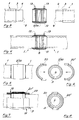
- Figure 1 shows a schematic representation of a preferred embodiment of the invention, parts such as pipes and sleeves, as they exist before the connection process.
- Two composite pipes 1 can be seen, which are to be connected by a connecting part 2.
- the choice of material for the outer shell or outer tube is optimized for linear and radial strength and non-positive connection, e.g. glass fiber reinforced plastic (GRP), the choice of material for the insert is optimized for chemical inertness and tightness of the connection, e.g. polyethylene (PE).
- GRP glass fiber reinforced plastic
- PE polyethylene
- the design of the pipe and sleeve is optimized for a material-appropriate connection, e.g. GRP / adhesive connection, PE / welded connection.
- the composite pipes consist of a rigid, relatively thin-walled outer tube 3 for force absorption and transmission and a softer, also relatively thin inner tube 4 for a tight connection and inert seal against the rigid outer wall.
- the connecting part 2 like the pipe, consists of a mechanically load-bearing connection outer shell 5, which forms a force bridge over the separate pipe parts, and a weldable sleeve body 10 as a sealing element between the separate inner pipe parts, which is preferably made of the same material as the inner pipe 4 or from one with the same weldable material.
- the welding energy is preferably introduced electrically.
- the connecting part 2 has a heating winding 12 integrated in the socket body 10 and electrical connections 13.
- the inner pipe is allowed to protrude at the connection point by about half the length of the socket body in the form of a free pipe stub 9, which in the assembled state comes to lie in the electroweldable sleeve body 10 and that a sleeve-shaped part 6 (like a push-in sleeve) is formed on both sides of the outer shell of the connecting part 2 in such a way that, after the pipes 1 have been inserted into the connecting part 2, the corresponding regions of the outer pipe sleeves 3 are encompassed .
- Locations filling points 15 provided for introducing the adhesive to be used, shown here at one of the possible locations.
- These are, for example, grommet-shaped openings through which the adhesive can be pressed in so that it can be distributed between the inner wall of the sleeve-shaped section 6 and the outer surface of the tube 1, this connection, as already mentioned, only non-positively but with respect to the medium to be transported does not have to be tight. This is a big advantage over pipe connections, which have to be joined and sealed by gluing.
- the protruding inner pipe stumps 9 are pushed into the sleeve body 10 when they are joined together and can be welded to each other in the areas of the heating winding 12, which is represented by the welding points 11.
- the material-appropriate connections, or the production of such connections, here adhesive technology and welding technology, are reliable experience; one does not take incalculable risks with the combined connection technology proposed here.
- the consequent separation of force-fit and tight connection in a separately optimizable procedure and simultaneous use, without one can negatively influence the other, but the advantages of both are retained, leads to an unprecedented result.
- Figure 2 shows the pipe connection of Figure 1 after the connection process.
- the positive connection 7 from one pipe to the other is ensured by the gluing point of the sleeve-shaped parts 6 and the mechanically load-bearing connection outer casing 5.
- the tight connection of the inner tubes 4 is ensured by the welding points 11, it being fluidically advantageous if the tube stubs 9 are joined together in a tube joint 8.
- FIGS. 3 to 8 show a variation.
- a connecting part produced as a unit
- the targeted pipe connection is then carried out in two steps.
- Figures 3 and 4 show the first step;
- Figures 5 and 6 show the second working step,
- Figures 7 and 8 show the finished pipe connection in a side view and in section.
- the two pipes 1 to be connected with the protruding pipe stubs 9 are inserted into a socket body 2/10 provided with a heating winding 12 and electrical connections which can be removed after use, butt butt butted (see point 8 according to FIG. 4) and welded tightly and with long-term suitability by means of electrical welding .
- a tight but only mechanically resilient inner tube connection is created according to FIG. 5.
- the desired external force connection in the area of the connection point is brought about by placing two shell-shaped half parts, the reinforcing shells 20, 20 'as a force transmission bridge according to FIG. 6.
- the two reinforcement shells which have a corresponding fit, are mutually bonded to one another, and also in the sleeve-shaped parts 6 and, as already discussed above, to the outer tube 3 of the composite tubes 1. It should be ensured that any cavities that arise between the inner pipe connection and the fit of the outer shell are filled with adhesive and filling compound.
- the finished pipe connection as shown in FIGS. 7 and 8, corresponds in terms of properties to the one discussed in connection with FIGS. 1 and 2.
Abstract
Description
Die Erfindung liegt auf dem Gebiet der Kunststoff-Rohrleitungssysteme und betrifft eine elektrisch schweissbare Rohrverbindung von Hartkunststoff-Rohren, insbesondere Verbundrohre aus glasfaserverstärkten Kunstharz-Werkstoffen gefertigt.The invention is in the field of plastic piping systems and relates to an electrically weldable pipe connection of hard plastic pipes, in particular composite pipes made of glass fiber reinforced synthetic resin materials.
Kunststoffe mit guter Verschweissbarkeit haben in zunehmenden Mass für den Rohrleitungsbau Bedeutung gewonnen und werden überall dort eingesetzt, wo es die Verträglichkeit gegenüber dem zu transportierenden Medium und die mechanische Festigkeit des entsprechenden Werkstoffes zulassen. Neben der Verschweissbarkeit, die auch auf Baustellen eine materialgerechte, dauerhafte Verbindung ermöglicht, spielt auch die meist vorzügliche Korrosionsbeständigkeit solch schweissbarer Thermoplaste eine wesentliche Rolle. Einzig die in der Regel eher niedrige mechanische Festigkeit limitiert in vielen Fällen den breiten Einsatz solcher Rohre auf Rohrleitungsnetze mit mittlerem bis niedrigem Betriebsdruck. Verwendet man bei Rohren trotzdem schweissbare Werkstoffe wie bspw. das weitverbreitete Polyäthylen, so bleibt nichts anderes übrig, als schon bei bescheidenen Betriebsdrücken verhältnismässig grosse Wanddicken einzusetzen. Mit den heute gängigen thermoplastischen Rohrwerkstoffen liegt die praktikable Obergrenze des Betriebsdruckes bei etwa 16 bar. Ausser dem erheblich höheren Materialbedarf und den damit verbundenen Kosten, ist, verglichen mit dünnwandigen Rohren aus mechanisch festeren Werkstoffen, ausserdem die reduzierte lichte Weite, mit anderen Worten, der geringere nutzbare Leitungsquerschnitt, nachteilig und unerwünscht.Plastics with good weldability have become increasingly important for pipeline construction and are used wherever the compatibility with the medium to be transported and the mechanical strength of the corresponding material allow. In addition to the weldability, which also enables a material-specific, permanent connection on construction sites, the mostly excellent corrosion resistance of such weldable thermoplastics also plays an important role. Only the generally rather low mechanical strength in many cases limits the wide use of such pipes on pipeline networks with medium to low operating pressure. If you still use weldable materials for pipes, such as the widely used polyethylene, there is no alternative but to use relatively large wall thicknesses even at modest operating pressures. With today's thermoplastic pipe materials, the practical upper limit of the operating pressure is around 16 bar. In addition to the significantly higher material requirements and thus associated costs is, compared to thin-walled pipes made of mechanically stronger materials, moreover, the reduced clear width, in other words, the smaller usable cable cross-section, disadvantageous and undesirable.
In den letzten Jahren haben speziell Hersteller von Polyäthylen-Rohrwerkstoffen (PE-Rohre) grosse Anstrengungen unternommen, um Materialtypen mit höherer mechanischer Festigkeit zu entwickeln und auf den Markt zu bringen. Die auf diese Weise erzielte faktische Erhöhung des Betriebsdruckes ist bisher eher bescheiden ausgefallen. Verglichen, mit den wesentlich höheren Festigkeitswerten von den im Rohrleitungsbau ebenfalls verwendeten glasfaserverstärkten Duroplastrohren (GFK-Rohre), scheint dies nicht der rechte Weg zu sein. Allerdings bietet der alleinige Einsatz von GFK-Rohren auch nicht die gewünschte breite Anwendungsmöglichkeit, denn diese Werkstoffe zeigen oft Limitierungen der Werkstoffeignung bezüglich der in solchen Rohren zu führenden Medien (bspw. Korrosion durch chemischen Angriff, Quellen durch Diffundation etc.) und bezüglich der Verbindungstechnik, die kompliziert, eher teuer und speziell auf der Baustelle in der Handhabung problematisch ist (bspw. dichte Klebeverbindung). Kleben ist, besonders im erdverlegten Rohrleitungsbau, obschon dies die eigentlich werkstoffgerechte Verbindungsweise wäre, mit Handhabungsproblemen und Qualitätsrisiken verbunden, insbesondere deswegen, weil die Dichtigkeit der Verbindung, die stets absoluten Vorrang hat, zur Hauptsache von der handwerklichen Geschicklichkeit des Rohrverlegers bzw. -monteurs abhängt.In recent years, manufacturers of polyethylene pipe materials (PE pipes) have made great efforts to develop and bring material types with higher mechanical strength onto the market. The actual increase in operating pressure achieved in this way has so far been rather modest. Compared to the much higher strength values of the glass fiber reinforced thermoset pipes (GRP pipes) also used in pipeline construction, this does not seem to be the right way. However, the sole use of GRP pipes does not offer the desired wide range of applications, because these materials often show limitations in the material suitability with regard to the media to be carried in such pipes (e.g. corrosion due to chemical attack, sources through diffusion, etc.) and with regard to the connection technology , which is complicated, rather expensive and particularly problematic to handle on the construction site (e.g. tight adhesive connection). Adhesive bonding, especially in underground pipeline construction, although this would be the connection method that is actually suitable for the material, involves handling problems and quality risks, in particular because the tightness of the connection, which always has absolute priority, depends primarily on the manual dexterity of the pipe installer or fitter .
So hat man Probleme und Einschränkungen in Kauf zu nehmen, wenn man GFK-Rohre einsetzt und man hat Einschränkungen in Kauf zu nehmen, wenn man Thermoplast-Rohre, bspw. PE-Rohre, einsetzt. Beide Rohrleitungssysteme haben ihren eigenen Stand der Technik erreicht und sind in ihrem, wie gesagt beschränkten Einsatzgebiet, sicher und zuverlässig verwendbar. PE-Rohre sind durch die recht einfache und heute normierte Elektroschweissung, der wirklich werkstoffgerechten Verbindungsweise, problemlos dicht und dauerhaft zu verbinden, wobei sich PE-Rohrwerkstoffe ausserdem zu sehr vielen durchleitbaren Fluiden neutral verhalten. Bei höheren Betriebsdrücken muss man allerdings passen. GFK-Rohrsysteme sind bezüglich der Herstellung dichter Verbindungen viel heikler und/oder sind dann mit einem erheblichen Risiko der Langzeittauglichkeit von solchen Rohr-Verbindungsstellen behaftet. Rohrsysteme aus GFK-Werkstoffen halten allerdings wesentlich höhere Betriebsdrücke aus. Dagegen büsst man beim Spektrum der durchleitbaren Fluiden einiges an Möglichkeiten ein.So you have to accept problems and restrictions when using GRP pipes and you have to accept restrictions when using thermoplastic pipes, e.g. PE pipes. Both piping systems have reached their own state of the art and are in their how said limited area of application, safe and reliable use. PE pipes can be easily and permanently connected due to the quite simple and now standardized electrical welding, the really material-specific connection method, whereby PE pipe materials are also neutral to a large number of passable fluids. At higher operating pressures, however, you have to fit. GRP pipe systems are much more delicate with regard to the production of tight connections and / or are then associated with a considerable risk of the long-term suitability of such pipe connection points. Pipe systems made of GRP materials can withstand much higher operating pressures. On the other hand, the range of fluids that can be passed through loses some of the possibilities.
Es ist somit Ziel der Erfindung, die diskutierten Vorteile so in die Gesamtfunktion zu integrieren, dass sie gleichzeitig nutzbar werden und die Nachteile derart von der Gesamtfunktion auszugrenzen, dass sie funktionsmässig nicht mitwirken können.It is therefore the aim of the invention to integrate the advantages discussed into the overall function in such a way that they can be used at the same time and to exclude the disadvantages from the overall function in such a way that they cannot functionally function.
Dieses Ziel wird durch die in den Patentansprüchen angegegebene Erfindung erreicht. Es ist im wesentlichen eine funktionale Kombination solcher Materialien derart, dass bei einem GFK-Rohranteil bspw. die Dichtigkeit der Verbindung untergeordnet ist, also keine speziellen handwerklichen Fähigkeiten auf der Baustelle erforderlich sind, dafür aber die Eigenschaften der Festigkeit ganz in den Vordergrund kommt und dass bei einem PE-Rohranteil die Festigkeit keine wesentliche Rolle spielt, dafür aber die leichter herzustellende Dichtigkeit und die weitgehend chemische Affinität bestens genutzt wird. Dies unter gleichzeitiger Nutzung bei Herstellung und Betrieb von Rohrleitungssystemen.This aim is achieved by the invention specified in the patent claims. It is essentially a functional combination of such materials in such a way that, for example, the tightness of the connection is subordinate to a GRP pipe part, i.e. no special manual skills are required on the construction site, but the properties of strength come to the fore and that The strength does not play an important role in a PE pipe component, but the easier to manufacture tightness and the largely chemical affinity are used in the best possible way. This with simultaneous use in the manufacture and operation of piping systems.
Konstruktiv umgesetzt führt das zu einem thermoplastischen Innenrohr und einem duroplastischen Aussenrohr, was auch auf die Verbindungsteile übertragen wird, wobei einfach handhabbare und langzeittaugliche Verbindungstechniken dieser Kombination massgebend sind. Diese Kombination wird durch eine besondere konstruktive Gestaltung herbeigeführt. Grob gesagt, rüstet man ein duroplastisches Aussenrohr mit einem thermoplastischen Innenrohr als Verbund-Rohr aus und die Verbindungsteile für solch ein Verbundrohr sind als elektroschweissbare Verbindungselemente ausgebildet.Constructively implemented, this leads to a thermoplastic inner tube and a thermosetting outer tube, which is also transferred to the connecting parts, whereby easy-to-use and long-term connection technologies of this combination are decisive. This combination is brought about by a special constructive design. Roughly speaking, a thermoset outer tube is equipped with a thermoplastic inner tube as a composite tube and the connecting parts for such a composite tube are designed as electroweldable connecting elements.
Die Rohrverbindungsteile sollen so gestaltet sein, dass einerseits das thermoplastische Innenrohr (liner) dicht und langzeittauglich verbunden wird und andererseits eine längs- und radialkraftschlüssige Verbindung der im Schweissbereich des Innenrohrs unterbrochenen, mechanisch beanspruchbaren Aussenrohrschicht der zu verbindenden, rohrförmigen Enden oder zu einer Steckmuffe ausgeformten Partie, zu einer durchgehenden, mechanisch belastbaren Einheit verbunden werden kann. Die Innenlage kann auch mehrschichtig sein, also ein mehrschichtiges "Innenrohr" aufweisen. Auf diese Weise hat man die Funktion der Dichtigkeit auf das thermoplastische Material und die Funktion der Festigkeit auf das duroplastische Material übertragen; wobei keines von beiden an den gesuchten Vorteilen des andern Werkstoffes teilhaben muss (liner muss keine hohe Festigkeit aufweisen, Aussenrohr muss nicht dicht sein). Die optimale und damit wesentliche werkstoffgerechte Verbindung beider Materialien wird beibehalten; der thermoplastische Werkstoff wird geschweisst, der duroplastische Werkstoff wird geklebt. Die Ausführung der Schweissung des thermoplastischen Innenrohrs ist anerkannt einfach in der Handhabung; die Verbindbarkeit der mechanisch tragfähigen GFK-Aussenschicht kann durch konstruktive Massnahmen baustellentauglich gestaltet werden.The pipe connection parts should be designed in such a way that the thermoplastic inner pipe (liner) is tightly and long-term connected on the one hand and on the other hand a longitudinal and radial non-positive connection of the mechanically stressable outer pipe layer of the tubular ends to be connected or formed into a push-in socket that is interrupted in the welding area of the inner pipe , can be connected to a continuous, mechanically resilient unit. The inner layer can also be multi-layer, ie have a multi-layer "inner tube". In this way, the function of tightness has been transferred to the thermoplastic material and the function of strength to the thermosetting material; whereby neither of the two needs to share in the desired advantages of the other material (liner does not have to have high strength, the outer tube does not have to be tight). The optimal and therefore essential material-appropriate connection of both materials is maintained; the thermoplastic material is welded, the thermosetting material is glued. The welding of the thermoplastic inner tube is recognized to be easy to use; the connectivity of the mechanically load-bearing GRP outer layer can be made suitable for construction sites by means of constructional measures.
Anhand der nachfolgend aufgeführten Figuren werden nun Ausführungsformen der Erfindung im Detail diskutiert.
- Figur 1
- zeigt eine erste konstruktive Ausgestaltung einer Rohr-Verbindung gemäss Erfindung vor dem Zusammensetzen und
Figur 2- zeigt die Rohr-Verbindung von Figur 1 nach dem Zusammensetzen.
Figur 3- zeigt eine zweite konstruktive Ausgestaltung einer Rohrverbindung gemäss Erfindung vor dem Zusammensetzen und
Figur 4- zeigt die Rohrverbindung von
Figur 3 nach dem Zusammensetzen des schweissbaren Innenteils. Figur 5- zeigt schematisch die gemäss den
Figuren 3 und 4 in einem vorbereiteten Arbeitsschritt zusammengesesetzte und dichte Rohrleitung, auf die nun der entsprechende Aussenteil der Rohrmuffe für eine Verbindung gemäss Erfindung in Form von offenen GFK-Halbschalen zur Herstellung des Kraftschlusses gesetzt wird und Figur 6- zeigt die Seitensicht der in
Figur 5 dargestellten beiden Halbschalen vor dem Zusammensetzen im Schnitt gesehen. Figur 7- zeigt die Muffe gemäss den
Figuren 5 und 6 nach dem kraftschlüssigen Zusammenfügen im Teilschnitt gesehen und Figur 8- zeigt die Muffe gemäss
Figur 7 nach dem kraftschlüssigen Zusammensetzen von der Seite gesehen.
- Figure 1
- shows a first constructive embodiment of a pipe connection according to the invention before assembly and
- Figure 2
- shows the pipe connection of Figure 1 after assembly.
- Figure 3
- shows a second constructive embodiment of a pipe connection according to the invention before assembly and
- Figure 4
- shows the pipe connection of Figure 3 after assembling the weldable inner part.
- Figure 5
- schematically shows the sealed pipeline assembled according to FIGS. 3 and 4 in a prepared work step, on which the corresponding outer part of the pipe sleeve for a connection according to the invention is now placed in the form of open GRP half-shells for producing the frictional connection and
- Figure 6
- shows the side view of the two half-shells shown in Figure 5 seen before assembly in section.
- Figure 7
- shows the sleeve according to Figures 5 and 6 seen after the positive connection in partial section and
- Figure 8
- shows the sleeve according to Figure 7 after the frictional assembly seen from the side.
Figur 1 zeigt in schematischer Darstellung eine bevorzugte Ausführungsform der Erfindung, Teile wie Rohre und Muffen, so wie sie vor dem Verbindungsvorgang vorliegen. Man erkennt zwei Verbund-Rohre 1, die durch einen Verbindungsteil 2 verbunden werden sollen. Die Materialwahl für die Aussenhülle bzw. Aussenrohr ist auf lineare und radiale Festigkeit und kraftschlüssige Verbindung optimiert, bspw. glasfaserverstärkter Kunststoff (GFK), die Materialwahl der Einlage ist auf chemische Inertheit und Dichtigkeit der Verbindung optimiert, bspw. Polyäthylen (PE). Die konstruktive Ausgestaltung von Rohr und Muffe ist auf materialgerechte Verbindung optimiert, bspw. GFK/Klebverbindung, PE/Schweissverbindung. Die Verbund-Rohre bestehen aus einem starren, verhältnismässig dünnwandigen Aussenrohr 3 zur Kraftaufnahme und -übertragung und einem weicheren, ebenfalls verhältnismässig dünnen Innenrohr 4 zur dichten Verbindung und inerten Abdichtung gegen die starre Aussenwandung. Das Verbindungsteil 2 besteht wie das Rohr aus einer mechanisch tragfähigen Verbindungs-Aussenhülle 5, eine Kraftbrücke über die getrennten Rohrteile bildend, und einem schweissbaren Muffenkörper 10 als Dichtelement zwischen den getrennten Innenrohrteilen, welcher vorzugsweise aus demselben Material wie das Innenrohr 4 oder aus einem mit diesem verschweissbaren Material besteht. Die Schweissenergie wird vorzugsweise elektrisch eingebracht. Dazu weist das Verbindungsteil 2 eine in den Muffenkörper 10 integrierte Heizwicklung 12 und elektrische Anschlüsse 13 auf. Zur konstruktiven Ausgestaltung gehört, um eine kraftschlüssige Verbindung einerseits und eine dichte Verbindung andererseits zwischen zwei Rohren herzustellen, dass man an den Rohren an der Verbindungsstelle das Innenrohr um ungefähr die halbe Länge des Muffenkörpers in Form eines freien Rohrstumpfes 9 vorstehen lässt, welcher im zusammengebauten Zustand in den elektroschweissbaren Muffenkörper 10 zu liegen kommt und dass an der Aussenhülle des Verbindungsteils 2 beidseitig eine muffenförmige Partie 6 (wie eine Steckmuffe) so angeformt wird, dass nach dem Einführen der Rohre 1 in das Verbindungsteil 2, die korrespondierenden Bereiche der Rohraussenhüllen 3 umfasst werden. Schliesslich sind am Verbindungsteil 2 an geeigneten Orten Einfüllstellen 15 zum Einbringen des zu verwendenden Klebstoff vorgesehen, hier an einer der möglichen Stellen angezeigt. Dies sind bspw. tüllenförmige Oeffnungen, durch die der Klebstoff eingepresst werden kann, damit er sich zwischen der Innenwandung der muffenförmigen Partie 6 und der Aussenfläche des Rohres 1 verteilen kann, wobei diese Verbindung, wie schon erwähnt, nur kraftschlüssig aber bezüglich des zu transportierenden Mediums nicht dicht sein muss. Dies ist ein grosser Vorteil gegenüber Rohrverbindungen, die durch Kleben vereinigt und dicht gemacht werden müssen.Figure 1 shows a schematic representation of a preferred embodiment of the invention, parts such as pipes and sleeves, as they exist before the connection process. Two composite pipes 1 can be seen, which are to be connected by a connecting
Die vorstehenden Innenrohrstümpfe 9 werden beim Zusammenfügen in den Muffenkörper 10 eingeschoben und können in den Bereichen der Heizwicklung 12 vollumfänglich miteinander dicht verschweisst werden, was durch die Schweissstellen 11 dargestellt ist. Die werkstoffgerechten Verbindungen, bzw. das Herstellen solcher Verbindungen, hier Klebetechnik und Schweisstechnik, sind gesicherte Erfahrung, man geht bei der hier vorgeschlagenen kombinierten Verbindungstechnik keine unkalkulierbaren Risiken ein. Die konsequente Trennung von kraftschlüssiger und dichter Verbindung in getrennt optimierbarer Vorgehensweise und gleichzeitiger Anwendung, ohne dass die eine die andere negativ beeinflussen kann, aber von beiden die Vorteile erhalten bleiben, führt zu einem bisher nicht erreichten Resultat.The protruding
Figur 2 zeigt die Rohrverbindung von Figur 1 nach dem Verbindungsvorgang. Man erkennt wieder die beiden, nun vereinigten Rohre 1 und den mit den Innenrohren dicht verschweissten Muffenkörper 10. Die kraftschlüssige Verbindung 7 von einem Rohr zum anderen ist über die Klebestelle der muffenförmigen Partien 6 und die mechanisch tragende Verbindungsaussenhülle 5 gewährleistet. Die dichte Verbindung der Innenrohre 4 ist durch die Schweissstellen 11 gewährleistet, wobei es strömungstechnisch vorteilhaft ist, wenn die Rohrstumpfe 9 in einem Rohrstoss 8 zusammengefügt sind.Figure 2 shows the pipe connection of Figure 1 after the connection process. One recognizes again the two, now combined pipes 1 and the
Eine Variation zeigen die Figuren 3 bis 8. An Stelle eines als eine Einheit hergestellten Verbindundsteils kann es wünschbar sein, die Rohrverbindung in Form eines getrennten als Muffenkörper ausgestalteten Innenteils und aufsetzbaren, schalenförmigen Aussenteilen herzustellen. Die angezielte Rohrverbindung wird dann in zwei Arbeitsschritten durchgeführt. Den ersten Arbeitsschritt zeigen die Figuren 3 und 4; den zweiten Arbeitsschritt zeigen die Figuren 5 und 6, die Figuren 7 und 8 zeigen die fertige Rohrverbindung in seitlicher Ansicht und im Schnitt.FIGS. 3 to 8 show a variation. Instead of a connecting part produced as a unit, it may be desirable to produce the pipe connection in the form of a separate inner part designed as a sleeve body and attachable, shell-shaped outer parts. The targeted pipe connection is then carried out in two steps. Figures 3 and 4 show the first step; Figures 5 and 6 show the second working step, Figures 7 and 8 show the finished pipe connection in a side view and in section.
Die beiden zu verbindenden Rohre 1 mit den vorstehenden Rohrstümpfen 9 werden in einen mit einer Heizwicklung 12 und nach Gebrauch entfernbaren elektrischen Anschlüssen versehenen Muffenkörper 2/10 eingeschoben, Stumpf auf Stumpf gestossen (siehe Stelle 8 gemäss Figur 4) und mittels Elektroschweissung dicht und langzeittauglich verschweisst. Auf diese Weise entsteht im ersten Arbeitsschritt eine dichte aber mechanisch nur bedingt belastbare Innenrohrverbindung gemäss Figur 5. Der gewünschte äussere Kraftschluss im Bereich der Verbindungsstelle wird durch Aufsetzen von zwei schalenförmigen Halbteilen, die Verstärkungsschalen 20,20' als Kraftübertragungsbrücke gemäss Figur 6 herbeigeführt. Die beiden Verstärkungsschalen, die eine entsprechende Passform aufweisen, werden gegenseitig miteinander, als auch in den muffenförmigen Partien 6 und, wie schon oben diskutiert, mit dem Aussenrohr 3 der Verbund-Rohre 1 verklebt. Dabei soll man darauf achten, dass allfällige, zwischen der Innenrohrverbindung und der Passform der Aussenhülle entstehende Hohlräume durch Klebe- und Füllmasse ausgefüllt werden. Die fertige Rohrverbindung, wie sie in den Figuren 7 und 8 gezeigt ist, entspricht bezüglich Eigenschaften einer solchen, wie sie im Zusammenhang mit den Figuren 1 und 2 diskutiert wurde.The two pipes 1 to be connected with the protruding
Claims (5)
Applications Claiming Priority (2)
| Application Number | Priority Date | Filing Date | Title |
|---|---|---|---|
| CH543/93 | 1993-02-22 | ||
| CH54393 | 1993-02-22 |
Publications (1)
| Publication Number | Publication Date |
|---|---|
| EP0612953A1 true EP0612953A1 (en) | 1994-08-31 |
Family
ID=4189427
Family Applications (1)
| Application Number | Title | Priority Date | Filing Date |
|---|---|---|---|
| EP19940810080 Withdrawn EP0612953A1 (en) | 1993-02-22 | 1994-02-11 | Connector for tubular plastic parts |
Country Status (3)
| Country | Link |
|---|---|
| US (1) | US5364130A (en) |
| EP (1) | EP0612953A1 (en) |
| CA (1) | CA2116083A1 (en) |
Cited By (3)
| Publication number | Priority date | Publication date | Assignee | Title |
|---|---|---|---|---|
| AT516006A1 (en) * | 2014-07-08 | 2016-01-15 | Jansen Ag | Arrangement with at least one composite pipe |
| CN107165712A (en) * | 2017-07-13 | 2017-09-15 | 广西玉柴机器股份有限公司 | Engine is segmented the connection sealing structure of blast pipe |
| DE102022101796A1 (en) | 2022-01-26 | 2023-07-27 | Basf Se | Method of connecting composite pipes |
Families Citing this family (50)
| Publication number | Priority date | Publication date | Assignee | Title |
|---|---|---|---|---|
| US5618065A (en) * | 1994-07-21 | 1997-04-08 | Hitachi Metals, Ltd. | Electric welding pipe joint having a two layer outer member |
| AU7154296A (en) * | 1995-09-06 | 1997-04-09 | Environ Products Inc. | Electric fusion welding of thermoplastic materials |
| US7498509B2 (en) | 1995-09-28 | 2009-03-03 | Fiberspar Corporation | Composite coiled tubing end connector |
| US5921285A (en) | 1995-09-28 | 1999-07-13 | Fiberspar Spoolable Products, Inc. | Composite spoolable tube |
| US8678042B2 (en) | 1995-09-28 | 2014-03-25 | Fiberspar Corporation | Composite spoolable tube |
| DE29521433U1 (en) * | 1995-12-19 | 1997-05-22 | Karl Heinz Krah Gmbh Werkzeug | Pipe or the like Fitting with electrical sleeve |
| US5690148A (en) * | 1996-06-21 | 1997-11-25 | Ziu; Christopher G. | Closure fitting and flexibility support assembly for double-containment piping systems |
| US5916468A (en) * | 1996-07-08 | 1999-06-29 | Hitachi Metals Ltd. | Electrically weldable pipe joint and production method thereof |
| GB2319576B (en) * | 1996-11-20 | 2001-02-07 | Uponor Bv | Pipe connector |
| US6043466A (en) * | 1998-02-20 | 2000-03-28 | Husky Injection Molding Systems Ltd. | Hot runner heating clamp |
| GB9805826D0 (en) * | 1998-03-18 | 1998-05-13 | South Staffordshire Waterworks | Pipe lining |
| DK0945665T3 (en) * | 1998-03-25 | 2001-09-03 | Bauku Troisdorfer Bau Und Kuns | Pipes, especially wound pipes |
| US6059319A (en) * | 1998-04-21 | 2000-05-09 | Floatec Corporation | Apparatus for forming field joints on plastic coated pipe |
| US6142483A (en) * | 1998-09-21 | 2000-11-07 | The United States Of America As Represented By The Administrator Of The National Aeronautics And Space Administration | Gasket assembly for sealing mating surfaces |
| IT244388Y1 (en) * | 1998-11-23 | 2002-03-11 | Nupi S P A | FITTINGS FOR DOUBLE WALL PIPES |
| FR2786429B1 (en) * | 1998-11-27 | 2001-01-19 | Seva | METHOD FOR CONNECTING TWO TUBES OF REINFORCED THERMOPLASTIC MATERIAL |
| US6406063B1 (en) | 1999-07-16 | 2002-06-18 | Fina Research, S.A. | Pipe fittings |
| ATE245264T1 (en) * | 1999-09-14 | 2003-08-15 | Petrotechnik Ltd | IMPROVED WELD SLEEVE |
| CA2857859A1 (en) * | 1999-10-01 | 2001-04-12 | Fiberspar Corporation | Composite coiled tubing end connector and pipe-to-pipe connector |
| US6446856B2 (en) * | 2000-03-06 | 2002-09-10 | Denso Corporation | Method of welding composite member |
| US6680464B1 (en) * | 2000-07-28 | 2004-01-20 | Zurn Industries, Inc. | Electrofusion joining control device |
| US6781099B2 (en) * | 2001-03-12 | 2004-08-24 | Karl-Heinz Krah Gmbh | Electrofusion socket forming system |
| AU2002259043A1 (en) | 2001-04-27 | 2002-11-11 | Fiberspar Corporation | Improved composite tubing |
| ITMI20012257A1 (en) * | 2001-10-26 | 2003-04-26 | Nupi S P A | MULTILAYER TUBE WITH WELDABLE END HEAD TO HEAD AND WELDING METHOD OF A MULTILAYER TUBE |
| US6761187B1 (en) * | 2003-04-03 | 2004-07-13 | Bayer Polymers Llc | Tubular assembly having an internal plug |
| US7523765B2 (en) | 2004-02-27 | 2009-04-28 | Fiberspar Corporation | Fiber reinforced spoolable pipe |
| US20060202471A1 (en) * | 2005-03-07 | 2006-09-14 | Weisbond Bradley K | Electro-fusion joining system for thermoplastic piping systems |
| US7472476B2 (en) * | 2005-09-21 | 2009-01-06 | Offshore Joint Services, Inc. | Method of applying joint infill cladding to pipe |
| US8187687B2 (en) | 2006-03-21 | 2012-05-29 | Fiberspar Corporation | Reinforcing matrix for spoolable pipe |
| US8839822B2 (en) | 2006-03-22 | 2014-09-23 | National Oilwell Varco, L.P. | Dual containment systems, methods and kits |
| CA2619808C (en) | 2007-02-02 | 2015-04-14 | Fiberspar Corporation | Multi-cell spoolable pipe |
| US8746289B2 (en) | 2007-02-15 | 2014-06-10 | Fiberspar Corporation | Weighted spoolable pipe |
| CA2641492C (en) | 2007-10-23 | 2016-07-05 | Fiberspar Corporation | Heated pipe and methods of transporting viscous fluid |
| US9127546B2 (en) | 2009-01-23 | 2015-09-08 | Fiberspar Coproation | Downhole fluid separation |
| GB0918955D0 (en) * | 2009-10-29 | 2009-12-16 | Pipeline Induction Heat Ltd | An apparatus for heating a pipe |
| US8955599B2 (en) | 2009-12-15 | 2015-02-17 | Fiberspar Corporation | System and methods for removing fluids from a subterranean well |
| CA2783764C (en) | 2009-12-15 | 2017-08-15 | Fiberspar Corporation | System and methods for removing fluids from a subterranean well |
| CA2923353C (en) | 2010-07-16 | 2018-05-01 | Ina Acquisition Corp. | Cured in place liner system and installation methods |
| FR2963654B1 (en) * | 2010-08-06 | 2013-12-13 | Saipem Sa | DRIVING COMPRISING AN INTERNAL SHAPING AND A TUBULAR JUNCTION SLEEVE OF PLASTIC MATERIAL |
| AU2012273037B2 (en) * | 2011-06-21 | 2016-09-01 | United Pipeline Systems, Inc. | Connections of lined pipe |
| EP2780619B1 (en) * | 2011-11-16 | 2018-09-05 | Shawcor Ltd. | Pipe connection assembly and method |
| EP2780159B1 (en) | 2011-11-16 | 2019-01-09 | Shawcor Ltd. | Flexible reinforced pipe and reinforcement tape |
| US9857003B2 (en) | 2012-02-17 | 2018-01-02 | Core Linepipe Inc. | Pipe, pipe connection and pipeline system |
| WO2014026190A1 (en) | 2012-08-10 | 2014-02-13 | National Oilwell Varco, L.P. | Composite coiled tubing connectors |
| TW201619539A (en) | 2014-11-21 | 2016-06-01 | 聖高拜塑膠製品公司 | Fluid transfer assembly |
| WO2016196356A1 (en) | 2015-05-29 | 2016-12-08 | Ina Acquisition Corp. | Process of liner connection for partial rehabilitation of a pipe system |
| US11231136B2 (en) | 2019-07-22 | 2022-01-25 | Ronald V. Andronaco | Flangeless coupler fused inside opposing ends of conduits |
| WO2022020309A1 (en) | 2020-07-20 | 2022-01-27 | Saudi Arabian Oil Company | Apparatus and method for welding reinforced thermosetting resin pipe joints by induction heating |
| EP4182155A1 (en) | 2020-07-20 | 2023-05-24 | Saudi Arabian Oil Company | Apparatus and method for electrofusion welding of reinforced thermosetting resin pipe joints |
| EP4182593A1 (en) | 2020-07-20 | 2023-05-24 | Saudi Arabian Oil Company | Apparatus and method for friction welding of reinforced thermosetting resin pipe joints |
Citations (5)
| Publication number | Priority date | Publication date | Assignee | Title |
|---|---|---|---|---|
| FR1516389A (en) * | 1966-03-01 | 1968-03-08 | American Cyanamid Co | Connection of plastic pipes |
| EP0337037A1 (en) * | 1988-04-11 | 1989-10-18 | Societe Alphacan | Tubes made of polyolefin resin for the realization of canalisations, sleeve tubes for their joining and method for their manufacture |
| EP0357551A1 (en) * | 1988-08-29 | 1990-03-07 | Geberit AG | Plastic profile for tubings |
| EP0390748A2 (en) * | 1989-03-31 | 1990-10-03 | Geberit AG | Welding socket |
| EP0465419A1 (en) * | 1990-07-05 | 1992-01-08 | Geberit AG | Electrically heated welding sleeve |
Family Cites Families (8)
| Publication number | Priority date | Publication date | Assignee | Title |
|---|---|---|---|---|
| US4101699A (en) * | 1973-11-23 | 1978-07-18 | Samuel Moore & Company | Synthetic resinous tube |
| US4096017A (en) * | 1977-02-18 | 1978-06-20 | H. C. Price Co. | Method and article for forming field joints on pipe coated with thermoplastic material |
| US4257630A (en) * | 1978-07-25 | 1981-03-24 | The Goodyear Tire & Rubber Company | Method and apparatus for splicing hose |
| NL8303190A (en) * | 1983-09-15 | 1985-04-01 | Wavin Bv | TUBE CONNECTION OF FIBER-REINFORCED PLASTIC TUBES. |
| US4927184A (en) * | 1986-11-07 | 1990-05-22 | Atochem | Pipes base on polyolefin resin for manufacturing pipelines and couplings for assembling them |
| US5150922A (en) * | 1989-01-11 | 1992-09-29 | Osaka Gas Co., Ltd. | Electrofusion joint and hot water supply header using the same |
| BE1002947A3 (en) * | 1989-03-17 | 1991-09-17 | Jonaco G M B H | PLASTIC COUPLER. |
| SU1656273A1 (en) * | 1989-03-24 | 1991-06-15 | Новосибирский Институт Инженеров Железнодорожного Транспорта | Method of sealing permanent pipe connections |
-
1994
- 1994-02-11 EP EP19940810080 patent/EP0612953A1/en not_active Withdrawn
- 1994-02-21 CA CA 2116083 patent/CA2116083A1/en not_active Abandoned
- 1994-02-22 US US08/199,066 patent/US5364130A/en not_active Expired - Fee Related
Patent Citations (5)
| Publication number | Priority date | Publication date | Assignee | Title |
|---|---|---|---|---|
| FR1516389A (en) * | 1966-03-01 | 1968-03-08 | American Cyanamid Co | Connection of plastic pipes |
| EP0337037A1 (en) * | 1988-04-11 | 1989-10-18 | Societe Alphacan | Tubes made of polyolefin resin for the realization of canalisations, sleeve tubes for their joining and method for their manufacture |
| EP0357551A1 (en) * | 1988-08-29 | 1990-03-07 | Geberit AG | Plastic profile for tubings |
| EP0390748A2 (en) * | 1989-03-31 | 1990-10-03 | Geberit AG | Welding socket |
| EP0465419A1 (en) * | 1990-07-05 | 1992-01-08 | Geberit AG | Electrically heated welding sleeve |
Cited By (4)
| Publication number | Priority date | Publication date | Assignee | Title |
|---|---|---|---|---|
| AT516006A1 (en) * | 2014-07-08 | 2016-01-15 | Jansen Ag | Arrangement with at least one composite pipe |
| CN107165712A (en) * | 2017-07-13 | 2017-09-15 | 广西玉柴机器股份有限公司 | Engine is segmented the connection sealing structure of blast pipe |
| CN107165712B (en) * | 2017-07-13 | 2018-08-21 | 广西玉柴机器股份有限公司 | Engine is segmented the connection sealing structure of exhaust pipe |
| DE102022101796A1 (en) | 2022-01-26 | 2023-07-27 | Basf Se | Method of connecting composite pipes |
Also Published As
| Publication number | Publication date |
|---|---|
| US5364130A (en) | 1994-11-15 |
| CA2116083A1 (en) | 1994-08-23 |
Similar Documents
| Publication | Publication Date | Title |
|---|---|---|
| EP0612953A1 (en) | Connector for tubular plastic parts | |
| DE60023502T2 (en) | WELDING MUFF WITH REINFORCEMENT FOR PLASTIC PIPES | |
| EP1756464B1 (en) | Connecting arrangement, particularly for the non-positive fastening of at least one fiber composite component to another component | |
| EP0075901A1 (en) | Process for providing a mantle tube connection across a joint between heat insulated pipes and pipe section for carrying out said process | |
| EP1705414A1 (en) | Arrangement with a tubular element | |
| WO2007048434A1 (en) | Fluid line and method for its production | |
| WO2014173653A2 (en) | Pipe element having a composite pipe and a metal connector | |
| EP0123195B1 (en) | Screwed-gland joint | |
| EP0493316A1 (en) | Device for connecting a weldable plastic or composite tube to a further conduit | |
| EP1677041A2 (en) | Connection arrangement for fluid conduits | |
| DE10340339A1 (en) | Method for joining bicycle frame elements of fiber reinforced plastics consists of providing the joint zone with a fiber reinforced, impregnated joining material, and using a pressurizing process | |
| DE3103235A1 (en) | UNIVERSAL SLEEVE FOR REMOTE CONNECTION OR POWER CABLE | |
| EP0813666B1 (en) | Hat-shaped connection sleeve for house service connections in sewer pipes | |
| EP2339596B1 (en) | Magnetic circuit separation for magnetic valve | |
| DE3936928A1 (en) | Electropneumatic two=part plug connector - establishes pneumatic line connection simultaneously with assembly of pin and socket electrical coupling | |
| DE102004008523A1 (en) | Pressure cylinders with a coated surface, useful for actuators or shock absorbers, comprises a metallic inner pipe, a metallic outer pipe and a core (made of fiber reinforced plastic) arranged between the outer and the inner pipes | |
| DE102006015918A1 (en) | valves | |
| EP1506921A1 (en) | Submarine retractable unit and method for its manufacture | |
| EP0461308B1 (en) | Transition piece for connecting plastic pipes with a metallic reinforcement, in particular in the sanitary and heating fields | |
| EP1431649B1 (en) | Plastic T-branch unit | |
| DE102018109998A1 (en) | Pipe connection system and method for producing a pipe connection | |
| EP0023997B1 (en) | Electrically insulating joint for coupling tubular extremities | |
| EP0692667B1 (en) | Pipe coupling | |
| DE19503579A1 (en) | Eyelet reinforcement of holes in thin fibre-reinforced thermoplastic mouldings | |
| DE202005019120U1 (en) | Connecting arrangement for bonding a fiber composite plastic pipe to a continuing component |
Legal Events
| Date | Code | Title | Description |
|---|---|---|---|
| PUAI | Public reference made under article 153(3) epc to a published international application that has entered the european phase |
Free format text: ORIGINAL CODE: 0009012 |
|
| AK | Designated contracting states |
Kind code of ref document: A1 Designated state(s): AT BE CH DE DK ES FR GB GR IE IT LI LU MC NL PT SE |
|
| 17P | Request for examination filed |
Effective date: 19950202 |
|
| GRAG | Despatch of communication of intention to grant |
Free format text: ORIGINAL CODE: EPIDOS AGRA |
|
| 17Q | First examination report despatched |
Effective date: 19960507 |
|
| GRAH | Despatch of communication of intention to grant a patent |
Free format text: ORIGINAL CODE: EPIDOS IGRA |
|
| STAA | Information on the status of an ep patent application or granted ep patent |
Free format text: STATUS: THE APPLICATION IS DEEMED TO BE WITHDRAWN |
|
| 18D | Application deemed to be withdrawn |
Effective date: 19961203 |