EP1431649B1 - Plastic T-branch unit - Google Patents
Plastic T-branch unit Download PDFInfo
- Publication number
- EP1431649B1 EP1431649B1 EP03025127A EP03025127A EP1431649B1 EP 1431649 B1 EP1431649 B1 EP 1431649B1 EP 03025127 A EP03025127 A EP 03025127A EP 03025127 A EP03025127 A EP 03025127A EP 1431649 B1 EP1431649 B1 EP 1431649B1
- Authority
- EP
- European Patent Office
- Prior art keywords
- pipe
- reinforcing ring
- tee joint
- pipe adapter
- socket
- Prior art date
- Legal status (The legal status is an assumption and is not a legal conclusion. Google has not performed a legal analysis and makes no representation as to the accuracy of the status listed.)
- Expired - Lifetime
Links
- 239000004033 plastic Substances 0.000 title claims description 6
- 229920003023 plastic Polymers 0.000 title claims description 6
- 230000003014 reinforcing effect Effects 0.000 claims abstract description 26
- 230000007704 transition Effects 0.000 claims abstract description 3
- 239000011324 bead Substances 0.000 claims description 9
- 239000000463 material Substances 0.000 claims description 9
- 238000003466 welding Methods 0.000 claims description 6
- 230000002787 reinforcement Effects 0.000 claims description 2
- 230000004323 axial length Effects 0.000 claims 1
- 239000004698 Polyethylene Substances 0.000 description 4
- 239000004743 Polypropylene Substances 0.000 description 4
- 238000000034 method Methods 0.000 description 4
- 229920000573 polyethylene Polymers 0.000 description 4
- 229920001155 polypropylene Polymers 0.000 description 4
- 238000004519 manufacturing process Methods 0.000 description 3
- 230000006378 damage Effects 0.000 description 2
- 239000012530 fluid Substances 0.000 description 2
- 238000010438 heat treatment Methods 0.000 description 2
- 238000003801 milling Methods 0.000 description 2
- -1 polyethylene Polymers 0.000 description 2
- 229920001169 thermoplastic Polymers 0.000 description 2
- 239000004416 thermosoftening plastic Substances 0.000 description 2
- 230000000052 comparative effect Effects 0.000 description 1
- 238000001816 cooling Methods 0.000 description 1
- 238000009661 fatigue test Methods 0.000 description 1
- 238000002347 injection Methods 0.000 description 1
- 239000007924 injection Substances 0.000 description 1
- 238000001746 injection moulding Methods 0.000 description 1
- 238000003754 machining Methods 0.000 description 1
- 238000005259 measurement Methods 0.000 description 1
- 239000007858 starting material Substances 0.000 description 1
- XLYOFNOQVPJJNP-UHFFFAOYSA-N water Substances O XLYOFNOQVPJJNP-UHFFFAOYSA-N 0.000 description 1
Images

Classifications
-
- F—MECHANICAL ENGINEERING; LIGHTING; HEATING; WEAPONS; BLASTING
- F16—ENGINEERING ELEMENTS AND UNITS; GENERAL MEASURES FOR PRODUCING AND MAINTAINING EFFECTIVE FUNCTIONING OF MACHINES OR INSTALLATIONS; THERMAL INSULATION IN GENERAL
- F16L—PIPES; JOINTS OR FITTINGS FOR PIPES; SUPPORTS FOR PIPES, CABLES OR PROTECTIVE TUBING; MEANS FOR THERMAL INSULATION IN GENERAL
- F16L47/00—Connecting arrangements or other fittings specially adapted to be made of plastics or to be used with pipes made of plastics
- F16L47/26—Connecting arrangements or other fittings specially adapted to be made of plastics or to be used with pipes made of plastics for branching pipes; for joining pipes to walls; Adaptors therefor
- F16L47/32—Branch units, e.g. made in one piece, welded, riveted
-
- B—PERFORMING OPERATIONS; TRANSPORTING
- B29—WORKING OF PLASTICS; WORKING OF SUBSTANCES IN A PLASTIC STATE IN GENERAL
- B29C—SHAPING OR JOINING OF PLASTICS; SHAPING OF MATERIAL IN A PLASTIC STATE, NOT OTHERWISE PROVIDED FOR; AFTER-TREATMENT OF THE SHAPED PRODUCTS, e.g. REPAIRING
- B29C65/00—Joining or sealing of preformed parts, e.g. welding of plastics materials; Apparatus therefor
- B29C65/02—Joining or sealing of preformed parts, e.g. welding of plastics materials; Apparatus therefor by heating, with or without pressure
- B29C65/18—Joining or sealing of preformed parts, e.g. welding of plastics materials; Apparatus therefor by heating, with or without pressure using heated tools
- B29C65/20—Joining or sealing of preformed parts, e.g. welding of plastics materials; Apparatus therefor by heating, with or without pressure using heated tools with direct contact, e.g. using "mirror"
-
- B—PERFORMING OPERATIONS; TRANSPORTING
- B29—WORKING OF PLASTICS; WORKING OF SUBSTANCES IN A PLASTIC STATE IN GENERAL
- B29C—SHAPING OR JOINING OF PLASTICS; SHAPING OF MATERIAL IN A PLASTIC STATE, NOT OTHERWISE PROVIDED FOR; AFTER-TREATMENT OF THE SHAPED PRODUCTS, e.g. REPAIRING
- B29C66/00—General aspects of processes or apparatus for joining preformed parts
- B29C66/01—General aspects dealing with the joint area or with the area to be joined
- B29C66/05—Particular design of joint configurations
- B29C66/10—Particular design of joint configurations particular design of the joint cross-sections
- B29C66/11—Joint cross-sections comprising a single joint-segment, i.e. one of the parts to be joined comprising a single joint-segment in the joint cross-section
- B29C66/114—Single butt joints
- B29C66/1142—Single butt to butt joints
-
- B—PERFORMING OPERATIONS; TRANSPORTING
- B29—WORKING OF PLASTICS; WORKING OF SUBSTANCES IN A PLASTIC STATE IN GENERAL
- B29C—SHAPING OR JOINING OF PLASTICS; SHAPING OF MATERIAL IN A PLASTIC STATE, NOT OTHERWISE PROVIDED FOR; AFTER-TREATMENT OF THE SHAPED PRODUCTS, e.g. REPAIRING
- B29C66/00—General aspects of processes or apparatus for joining preformed parts
- B29C66/01—General aspects dealing with the joint area or with the area to be joined
- B29C66/32—Measures for keeping the burr form under control; Avoiding burr formation; Shaping the burr
- B29C66/322—Providing cavities in the joined article to collect the burr
-
- B—PERFORMING OPERATIONS; TRANSPORTING
- B29—WORKING OF PLASTICS; WORKING OF SUBSTANCES IN A PLASTIC STATE IN GENERAL
- B29C—SHAPING OR JOINING OF PLASTICS; SHAPING OF MATERIAL IN A PLASTIC STATE, NOT OTHERWISE PROVIDED FOR; AFTER-TREATMENT OF THE SHAPED PRODUCTS, e.g. REPAIRING
- B29C66/00—General aspects of processes or apparatus for joining preformed parts
- B29C66/50—General aspects of joining tubular articles; General aspects of joining long products, i.e. bars or profiled elements; General aspects of joining single elements to tubular articles, hollow articles or bars; General aspects of joining several hollow-preforms to form hollow or tubular articles
- B29C66/51—Joining tubular articles, profiled elements or bars; Joining single elements to tubular articles, hollow articles or bars; Joining several hollow-preforms to form hollow or tubular articles
- B29C66/52—Joining tubular articles, bars or profiled elements
- B29C66/522—Joining tubular articles
- B29C66/5224—Joining tubular articles for forming fork-shaped connections, e.g. for making Y-shaped pieces
- B29C66/52241—Joining tubular articles for forming fork-shaped connections, e.g. for making Y-shaped pieces with two right angles, e.g. for making T-shaped pieces
-
- B—PERFORMING OPERATIONS; TRANSPORTING
- B29—WORKING OF PLASTICS; WORKING OF SUBSTANCES IN A PLASTIC STATE IN GENERAL
- B29C—SHAPING OR JOINING OF PLASTICS; SHAPING OF MATERIAL IN A PLASTIC STATE, NOT OTHERWISE PROVIDED FOR; AFTER-TREATMENT OF THE SHAPED PRODUCTS, e.g. REPAIRING
- B29C66/00—General aspects of processes or apparatus for joining preformed parts
- B29C66/70—General aspects of processes or apparatus for joining preformed parts characterised by the composition, physical properties or the structure of the material of the parts to be joined; Joining with non-plastics material
- B29C66/71—General aspects of processes or apparatus for joining preformed parts characterised by the composition, physical properties or the structure of the material of the parts to be joined; Joining with non-plastics material characterised by the composition of the plastics material of the parts to be joined
-
- B—PERFORMING OPERATIONS; TRANSPORTING
- B29—WORKING OF PLASTICS; WORKING OF SUBSTANCES IN A PLASTIC STATE IN GENERAL
- B29C—SHAPING OR JOINING OF PLASTICS; SHAPING OF MATERIAL IN A PLASTIC STATE, NOT OTHERWISE PROVIDED FOR; AFTER-TREATMENT OF THE SHAPED PRODUCTS, e.g. REPAIRING
- B29C66/00—General aspects of processes or apparatus for joining preformed parts
- B29C66/70—General aspects of processes or apparatus for joining preformed parts characterised by the composition, physical properties or the structure of the material of the parts to be joined; Joining with non-plastics material
- B29C66/73—General aspects of processes or apparatus for joining preformed parts characterised by the composition, physical properties or the structure of the material of the parts to be joined; Joining with non-plastics material characterised by the intensive physical properties of the material of the parts to be joined, by the optical properties of the material of the parts to be joined, by the extensive physical properties of the parts to be joined, by the state of the material of the parts to be joined or by the material of the parts to be joined being a thermoplastic or a thermoset
- B29C66/739—General aspects of processes or apparatus for joining preformed parts characterised by the composition, physical properties or the structure of the material of the parts to be joined; Joining with non-plastics material characterised by the intensive physical properties of the material of the parts to be joined, by the optical properties of the material of the parts to be joined, by the extensive physical properties of the parts to be joined, by the state of the material of the parts to be joined or by the material of the parts to be joined being a thermoplastic or a thermoset characterised by the material of the parts to be joined being a thermoplastic or a thermoset
- B29C66/7392—General aspects of processes or apparatus for joining preformed parts characterised by the composition, physical properties or the structure of the material of the parts to be joined; Joining with non-plastics material characterised by the intensive physical properties of the material of the parts to be joined, by the optical properties of the material of the parts to be joined, by the extensive physical properties of the parts to be joined, by the state of the material of the parts to be joined or by the material of the parts to be joined being a thermoplastic or a thermoset characterised by the material of the parts to be joined being a thermoplastic or a thermoset characterised by the material of at least one of the parts being a thermoplastic
- B29C66/73921—General aspects of processes or apparatus for joining preformed parts characterised by the composition, physical properties or the structure of the material of the parts to be joined; Joining with non-plastics material characterised by the intensive physical properties of the material of the parts to be joined, by the optical properties of the material of the parts to be joined, by the extensive physical properties of the parts to be joined, by the state of the material of the parts to be joined or by the material of the parts to be joined being a thermoplastic or a thermoset characterised by the material of the parts to be joined being a thermoplastic or a thermoset characterised by the material of at least one of the parts being a thermoplastic characterised by the materials of both parts being thermoplastics
Definitions
- the invention relates to a T-piece made of plastic for connecting an outgoing pipe to a pipeline, wherein the tee has two aligned first and second pipe socket, which emanate from a central reinforcement, at the third pipe socket with the first and second pipe socket is formed in a substantially vertical orientation, to which a connection pipe section is attached by means of heating element butt welding for connection of the outgoing pipe.
- Plastic tees are used to create pipe outlets in pipelines for transporting fluids such as e.g. Gas or water used. According to DIN 16962/63, such tees are made of polyethylene (PE) or polypropylene (PP).
- PE polyethylene
- PP polypropylene
- the second method is eg off DE 34 04 294 C1 known.
- a previously cut to length extruded tubular body is reinforced over a substantial portion of its length by multilayer wrapping with extruded thermoplastic strip material to form a substantially cylindrical collar radially outward.
- the band material is heated when wrapping the tubular body to firmly weld the layers of the strip material both to the tubular body and to each other.
- branch holes are made in the collar after cooling of the strip material transverse or angled to the axis of the tubular body and the collar also machined, the collar at each of its two axial ends to form a groove is turned off the front side.
- the collar Before the production of the branch bores, the collar is first turned off flat in the region of the connecting piece to be produced parallel to the axis of the tubular body and in the region on the opposite side at an angle to the tube axis. Subsequently, the substantially cylindrical connecting piece is produced on the collar in each case around the branch bores.
- the cross section of each of the turned-on connecting pieces corresponds to the cross section of an outgoing pipe string, so that these pipe strings can be firmly and permanently connected by simple butt welding with the pipe fitting.
- the starting material for the T-piece is a hollow rod made of PE or PP of length I and having an inner diameter D i and an outer diameter D a .
- the outer shell of the hollow rod is turned off at the two ends and thereby the respective annular, in Fig. 4 hatched material areas A and B removed.
- a rotational body with an outer contour, as seen from the lower half of the Fig. 4 is recognizable.
- On the side at which the branching pipe is to be attached becomes a flat, parallel to the longitudinal axis L of the pipe Milling made with the hatched area of material designated C is removed.
- the inner diameter d i of the third Rohstutzens 13 is equal to the inner diameter D i of the first and second pipe sockets 11, 12 and the outer diameter of the third Rohstutzens 13 equal to the outer diameter d a of the first and second pipe sockets 11, 12.
- T-pieces produced in this way can be produced relatively inexpensively even in larger dimensions and have proven very successful in practice.
- the object of the invention is to make a T-piece so that this imminent danger is avoided, wherein it is the invention of further essential to no longer use plastic material or have to resort to increased wall thicknesses.
- the invention solves this problem by the features of claim 1 and is accordingly characterized in that the transition region between the third pipe socket and the pipe piece welded thereto is comprised of a reinforcing ring, the outside of the pipe socket and an adjoining axial portion of the connecting pipe section tightly encloses.
- This reinforcing ring preferably consists, like the T-piece, of PE or PP. Comparative measurements have shown that this task is extremely satisfactorily solved by this technically very simple measure. It should be emphasized in this context that the tee otherwise completely or almost completely corresponds to the prior art. Therefore, it is also possible to retrofit existing T-pieces of this known type subsequently easily in terms of higher stability and continuous operating strength in the simplest way.
- the inner diameter of the reinforcing ring and the outer diameter of the connecting pipe piece to each other have a sliding clearance, so that a manual sliding over of the reinforcing ring on the connecting pipe piece is possible, the reinforcing ring is thus attachable without tools.
- an advantageous feature is that in the welding connection region between the third pipe socket and the connecting pipe piece, a circumferential weld bead is formed, which is surrounded by the reinforcing ring, wherein the reinforcing ring can form a receiving pocket for the weld bead on its end portion facing the third pipe socket ,
- the receiving pocket may be formed as an undercut annular groove, which is frontally bounded by at least one inwardly facing collar portion, which traps the weld bead substantially form-locking or snap-fit.
- This is an extremely simple self-locking fixation of the reinforcing ring achieved, which can be otherwise designed so that the reinforcing ring can not be removed from its anchorage without the aid of tools.
- the at least one collar portion can be formed as a circumferential annular collar.
- T-piece 10 shown initially corresponds almost completely to the T-piece according to the prior art as in Fig. 4 shown.
- Essential to the invention is a designated 16 reinforcing ring.
- the reinforcing ring 16 preferably obtained by machining from a cut-to-length portion of a hollow rod is pushed from the end face 14 a of the pipe section 14 to this until it abuts the central central portion of the tee 10. Since the sliding over of the reinforcing ring 16 should be performed by hand if possible, there is preferably between the inner diameter of the reinforcing ring 16 and the outer diameter of the pipe section 14, a sufficient Gleitschulsspiel, possibly a slight interference fit.
- the reinforcing ring 16 has a pocket-like inner recess 18 in its one end region 17.
- the receiving pocket 18 and the reinforcing ring 16 inwardly projecting collar 19 located at the outermost end of the receiving pocket 18 and the reinforcing ring 16 inwardly projecting collar 19, the - after previous temporary widening when snapping over the weld bead 15 - in the final assembly the weld bead 15 behind which then remains in the undercut annular groove, which preferably forms the receiving pocket, is arranged.
Abstract
Description
Die Erfindung betrifft ein T-Stück aus Kunststoff zum Anschluss eines abgehenden Rohres an eine Rohrleitung, wobei das T-Stück zwei in Flucht liegende erste und zweite Rohrstutzen aufweist, die von einer zentralen Verstärkung ausgehen, an der ein dritter Rohrstutzen mit zu den ersten und zweiten Rohrstutzen im wesentlichen senkrechter Orientierung ausgebildet ist, an welchem zum Anschluss des abgehenden Rohres ein Verbindungs-Rohrstück mittels Heizelement-Stumpfschweißung angebracht ist.The invention relates to a T-piece made of plastic for connecting an outgoing pipe to a pipeline, wherein the tee has two aligned first and second pipe socket, which emanate from a central reinforcement, at the third pipe socket with the first and second pipe socket is formed in a substantially vertical orientation, to which a connection pipe section is attached by means of heating element butt welding for connection of the outgoing pipe.
T-Stücke aus Kunststoff werden zur Erzeugung von Rohrabgängen in Rohrleitungen zum Transport von Fluiden wie z.B. Gas oder Wasser eingesetzt. Nach DIN 16962/63 sind solche T-Stücke aus Polyethylen (PE) oder Polypropylen (PP) gefertigt.Plastic tees are used to create pipe outlets in pipelines for transporting fluids such as e.g. Gas or water used. According to DIN 16962/63, such tees are made of polyethylene (PE) or polypropylene (PP).
Im Anschlussbereich des abgehenden Rohres, also im Zentrum des T-Stücks, müssen die Wandungen wegen der auftretenden Innendruckverhältnisse verstärkt sein. Bekannt sind im wesentlichen drei wichtige Herstellungsverfahren für T-Stücke aus Kunststoff.In the connection area of the outgoing pipe, ie in the center of the T-piece, the walls must be reinforced because of the internal pressure conditions occurring. Essentially three important production processes for plastic tees are known.
Bei dem ersten Verfahren wird ein komplettes T-Stück im Spritzgießverfahren erzeugt. Dies ist wegen der kostspieligen Spritzgießwerkzeuge ein relativ aufwendiges Verfahren, das sich auch nur für T-Stücke eignet, die gewisse Dimensionen nicht überschreiten.In the first method, a complete T-piece is produced by injection molding. This is a relatively expensive process because of the expensive injection molds, which is only suitable for tees that do not exceed certain dimensions.
Das zweite Verfahren ist z.B. aus
Vor der Herstellung der Abzweigbohrungen wird der Kragen zunächst im Bereich des herzustellenden Anschlussstutzens parallel zur Achse des Rohrkörpers und im Bereich an der gegenüberliegenden Seite winklig zur Rohrachse flach abgedreht. Anschließend wird an dem Kragen jeweils rings um die Abzweigbohrungen der im wesentlichen zylindrische Anschlussstutzen hergestellt. Der Querschnitt jedes der angedrehten Anschlussstutzen entspricht dabei dem Querschnitt eines abgehenden Rohrstranges, so dass diese Rohrstränge durch einfaches Stumpfschweißen mit dem Rohrformstück fest und dauerhaft verbunden werden können.Before the production of the branch bores, the collar is first turned off flat in the region of the connecting piece to be produced parallel to the axis of the tubular body and in the region on the opposite side at an angle to the tube axis. Subsequently, the substantially cylindrical connecting piece is produced on the collar in each case around the branch bores. The cross section of each of the turned-on connecting pieces corresponds to the cross section of an outgoing pipe string, so that these pipe strings can be firmly and permanently connected by simple butt welding with the pipe fitting.
Bei dem dritten Verfahren wird ein Hohlstab spanabhebend bearbeitet, wie es nunmehr anhand von
Ausgangsmaterial für das insgesamt mit 10 bezeichnete T-Stück ist ein Hohlstab aus PE bzw. PP der Länge I sowie mit einem Innendurchmesser Di und einem Außendurchmesser Da. Zur Bildung des ersten Rohrstutzens 11 und des zweiten, mit diesem in Flucht der nicht dargestellten Rohrleitung liegenden, Rohrstutzens 12 wird der Außenmantel des Hohlstabs an den beiden Enden abgedreht und dadurch die jeweils ringförmigen, in
In der Regel ist der Innendurchmesser di des dritten Rohstutzens 13 gleich dem Innendurchmesser Di der ersten und zweiten Rohrstutzen 11, 12 und der Außendurchmesser des dritten Rohstutzens 13 gleich dem Außendurchmesser da der ersten und zweiten Rohrstutzen 11, 12. Dadurch können die an drei Seiten an das T-Stück anzuschließenden Rohre bzw. Rohrleitungen dieselbe Nenngröße aufweisen.In general, the inner diameter d i of the third Rohstutzens 13 is equal to the inner diameter D i of the first and
Mittels Heizelement-Stumpfschweißung wird schließlich an die Stirnseite des kurzen dritten Rohrstutzens 13 ein im Querschnitt gleich bemaßtes Rohrstück 14 angeschweißt, wobei sich mantelaußenseitig ein im wesentlichen umlaufender Schweißwulst 15 ergibt.By means of heating element butt welding is finally welded to the front side of the short
Solchermaßen hergestellte T-Stücke, von der vorliegende Erfindung ausgeht, lassen sich relativ kostengünstig auch in größeren Dimensionen erzeugen und haben sich in der Praxis sehr bewährt.T-pieces produced in this way, based on the present invention, can be produced relatively inexpensively even in larger dimensions and have proven very successful in practice.
Dauerfestigkeitsprüfungen haben indes gezeigt, dass insbesondere im Bereich des Anschlusses des dritten Rohrstücks 14 nach vielen Jahren Dauerbetriebs einer unter Innendruck stehenden Fluidleitung möglicherweise mit Ausbeulungen zu rechnen ist, was letztlich zu einer Beschädigung des T-Stücks bis hin zur Zerstörung führen könnte.Fatigue tests have shown, however, that in particular in the area of the connection of the
Aufgabe der Erfindung ist es, ein T-Stück so zu gestalten, dass diese drohende Gefahr vermieden wird, wobei es der Erfindung des weiteren wesentlich darauf ankommt, nicht mehr Kunststoffmaterial verwenden oder auf erhöhte Wandstärken zurückgreifen zu müssen.The object of the invention is to make a T-piece so that this imminent danger is avoided, wherein it is the invention of further essential to no longer use plastic material or have to resort to increased wall thicknesses.
Die Erfindung löst diese Aufgabe durch die Merkmale des Anspruches 1 und ist dem entsprechend dadurch gekennzeichnet, dass der Übergangsbereich zwischen dem dritten Rohrstutzen und dem daran angeschweißten Rohrstück von einem Verstärkungsring umfasst ist, der den Rohrstutzen und einen daran anschließenden axialen Bereich des Verbindungs-Rohrstücks außenmantelseitig eng umschließt.The invention solves this problem by the features of claim 1 and is accordingly characterized in that the transition region between the third pipe socket and the pipe piece welded thereto is comprised of a reinforcing ring, the outside of the pipe socket and an adjoining axial portion of the connecting pipe section tightly encloses.
Zur Verwirklichung der Erfindung bedarf es demnach lediglich des auf das Rohrstück aufgeschobenen und den Schweiß-Verbindungsbereich eng umschließenden Verstärkungsringes. Dieser Verstärkungsring besteht vorzugsweise, wie das T-Stück, aus PE bzw. PP. Vergleichsmessungen haben erwiesen, dass durch diese technisch überaus einfache Maßnahme die gestellte Aufgabe äußerst befriedigend gelöst wird. Hervorzuheben ist in diesem Zusammenhang, dass das T-Stück ansonsten vollständig oder doch nahezu vollständig dem bisherigen Stand der Technik entspricht. Deshalb ist es auch möglich, bereits existierende T-Stücke dieser bekannten Bauart nachträglich ohne weiteres im Sinne höherer Stabilität und Dauerbetriebsfestigkeit auf einfachste Art nachrüsten zu können.To realize the invention, it is therefore only necessary to have the reinforcing ring pushed onto the pipe section and closely surrounding the welding connection area. This reinforcing ring preferably consists, like the T-piece, of PE or PP. Comparative measurements have shown that this task is extremely satisfactorily solved by this technically very simple measure. It should be emphasized in this context that the tee otherwise completely or almost completely corresponds to the prior art. Therefore, it is also possible to retrofit existing T-pieces of this known type subsequently easily in terms of higher stability and continuous operating strength in the simplest way.
In weiterer Ausgestaltung dieses erfindungsgemäßen Prinzips kann der Innendurchmesser des Verstärkungsringes und der Außendurchmesser des Verbindungs-Rohrstücks zueinander ein Gleitspiel aufweisen, so dass ein händisches Überschieben des Verstärkungsringes über das Verbindungs-Rohrstück möglich ist, der Verstärkungsring also werkzeuglos anbringbar ist.In a further embodiment of this inventive principle, the inner diameter of the reinforcing ring and the outer diameter of the connecting pipe piece to each other have a sliding clearance, so that a manual sliding over of the reinforcing ring on the connecting pipe piece is possible, the reinforcing ring is thus attachable without tools.
Des weiteren besteht ein vorteilhaftes Merkmal darin, dass im Schweißanschlussbereich zwischen dem dritten Rohrstutzen und dem Verbindungs-Rohrstück ein umlaufender Schweißwulst ausgebildet ist, der von dem Verstärkungsring umfasst ist, wobei der Verstärkungsring an seinem dem dritten Rohrstutzen zugewandten Endabschnitt eine Aufnahmetasche für den Schweißwulst ausbilden kann.Furthermore, an advantageous feature is that in the welding connection region between the third pipe socket and the connecting pipe piece, a circumferential weld bead is formed, which is surrounded by the reinforcing ring, wherein the reinforcing ring can form a receiving pocket for the weld bead on its end portion facing the third pipe socket ,
Entsprechend einer erfindungsgemäßen Weiterbildung kann die Aufnahmetasche als hinterschnittene Ringnut ausgebildet sein, die stirnseitig von wenigstens einem nach innen weisenden Kragenabschnitt begrenzt ist, der den Schweißwulst im wesentlichen form- bzw. rastschlüssig hinterfängt. Hiermit ist eine überaus einfache selbstsichernde Fixierung des Verstärkungsringes erzielt, die im übrigen so beschaffen sein kann, dass sich der Verstärkungsring aus seiner Verankerung nicht mehr ohne Zuhilfenahme von Werkzeug entfernen lässt. Im übrigen kann der wenigstens eine Kragenabschnitt als umlaufender Ringkragen ausbildet sein.According to a development of the invention, the receiving pocket may be formed as an undercut annular groove, which is frontally bounded by at least one inwardly facing collar portion, which traps the weld bead substantially form-locking or snap-fit. This is an extremely simple self-locking fixation of the reinforcing ring achieved, which can be otherwise designed so that the reinforcing ring can not be removed from its anchorage without the aid of tools. Moreover, the at least one collar portion can be formed as a circumferential annular collar.
Die Erfindung versteht sich im übrigen am besten anhand der nachfolgenden Beschreibung eines in den Zeichnungen dargestellten Ausführungsbeispiels. In den Zeichnungen zeigen:
- Fig. 1
- in teilweisem Längsschnitt ein entsprechend der Erfindung mit einem Verstärkungsring versehenes T-Stück,
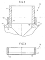
- Fig. 2
- eine gegenüber
Fig. 1 vergrößert widergegebene Ausschnittsdarstellung im Anschlussbereich des Rohrstücks, - Fig. 3
- einen Längsschnitt durch den Verstärkungsring und
- Fig. 4
- das oben bereits eingehend erläuterte T-Stück nach dem Stand der Technik.
- Fig. 1
- in a partial longitudinal section a according to the invention provided with a reinforcing ring tee,
- Fig. 2
- one opposite
Fig. 1 enlarged reproduced sectional representation in the connection region of the pipe section, - Fig. 3
- a longitudinal section through the reinforcing ring and
- Fig. 4
- the above already explained in detail T-piece according to the prior art.
Das in den
Der Verstärkungsring 16, vorzugsweise durch spanende Bearbeitung aus einem abgelängten Abschnitt eines Hohlstabes gewonnen, wird von der Endstirnseite 14a des Rohrstücks 14 auf dieses aufgeschoben, bis es am mittigen Zentralabschnitt des T-Stücks 10 anschlägt. Da das Überschieben des Verstärkungsringes 16 nach Möglichkeit von Hand ausgeführt werden sollte, besteht vorzugsweise zwischen dem Innendurchmesser des Verstärkungsrings 16 und dem Außendurchmesser des Rohrstücks 14 ein hinreichendes Gleitbewegungsspiel, allenfalls eine leichte Klemmpassung.The reinforcing
Der Verstärkungsring 16 weist in seinem einen Endbereich 17 eine taschenartige Innenausnehmung 18 auf. Mit dieser übergreift er den Schweißwulst 15. Bei einer bevorzugten Ausführungsform befindet sich an der äußersten Stirnseite der Aufnahmetasche 18 und des Verstärkungsrings 16 ein nach einwärts ragender Kragen 19, der - nach vorheriger vorübergehender Aufweitung beim Überrasten über den Schweißwulst 15 - in der Endmontagelage den Schweißwulst 15 hinterfängt, welcher sodann in der hinterschnittenen Ringnut, die die Aufnahmetasche vorzugsweise ausbildet, angeordnet bleibt.The reinforcing
Zwar zeigen die Figuren das T-Stück stark verkleinert, jedoch hinsichtlich aller Abmessungen in den richtigen Proportionen. Daraus ist erkennbar, dass der Verstärkungsring ein recht kleines und - im Vergleich mit dem Rohrstück 14 - auch relativ kurzes Bauteil darstellt.Although the figures show the T-piece greatly reduced, but in terms of all dimensions in the correct proportions. It can be seen that the reinforcing ring is a fairly small and - compared to the pipe section 14 - also relatively short component.
Claims (7)
- Tee joint and pipe adapter, wherein the tee joint (10) made of plastics material is suitable for connecting an outgoing pipe to a pipeline, wherein the tee joint (10) comprises two aligned first and second pipe sockets (11, 12) that emanate from a central reinforcement, on which there is formed with an orientation substantially perpendicular to the first and second pipe sockets (11, 12) a third pipe socket (13), to which there is attached by means of heated-tool butt welding a pipe adapter (14), which is used to connect the outgoing pipe, characterized in that the transition region between the third pipe socket (13) and the pipe adapter (14) welded thereon is encircled by a reinforcing ring (16), which tightly surrounds the outer lateral surface of the pipe socket (13) and an axial region of the pipe adapter (14) adjacent thereto.
- Tee joint and pipe adapter according to claim 1, characterized in that the inside diameter of the reinforcing ring (16) and the outside diameter of the pipe adapter have sliding clearance relative to one another, thereby allowing the reinforcing ring (16) to be slipped manually over the pipe adapter (14).
- Tee joint and pipe adapter according to claim 1 or 2, characterized in that in the region of the welded joint between the third pipe socket (13) and the pipe adapter (14) a circumferential weld bead (15) is formed, which is encircled by the reinforcing ring (16).
- Tee joint and pipe adapter according to claim 3, characterized in that the reinforcing ring (16) on its end portion facing the third pipe socket (13) forms a receiving pocket (18) for the weld bead (15).
- Tee joint and pipe adapter according to claim 4, characterized in that the receiving pocket (18) takes the form of an undercut annular groove, which is delimited at the front by at least one inwardly directed collar portion (19), which catches in a substantially positive- and/or detent-locking manner behind the weld bead (15).
- Tee joint and pipe adapter according to claim 5, characterized in that the at least one collar portion (19) takes the form of a circumferential annular collar.
- Tee joint and pipe adapter according to one of claims 4 to 6, characterized in that the axial extent of the receiving pocket (18) is approximately a fifth to a quarter of the total axial length of the reinforcing ring (16).
Applications Claiming Priority (2)
| Application Number | Priority Date | Filing Date | Title |
|---|---|---|---|
| DE10259143A DE10259143B3 (en) | 2002-12-18 | 2002-12-18 | T-joint for connecting tubes of pipeline has transition region between third connector and tube piece welded to it surrounded by reinforcing ring |
| DE10259143 | 2002-12-18 |
Publications (3)
| Publication Number | Publication Date |
|---|---|
| EP1431649A2 EP1431649A2 (en) | 2004-06-23 |
| EP1431649A3 EP1431649A3 (en) | 2005-05-11 |
| EP1431649B1 true EP1431649B1 (en) | 2008-04-02 |
Family
ID=32049654
Family Applications (1)
| Application Number | Title | Priority Date | Filing Date |
|---|---|---|---|
| EP03025127A Expired - Lifetime EP1431649B1 (en) | 2002-12-18 | 2003-11-03 | Plastic T-branch unit |
Country Status (4)
| Country | Link |
|---|---|
| EP (1) | EP1431649B1 (en) |
| AT (1) | ATE391266T1 (en) |
| DE (2) | DE10259143B3 (en) |
| DK (1) | DK1431649T3 (en) |
Cited By (1)
| Publication number | Priority date | Publication date | Assignee | Title |
|---|---|---|---|---|
| EP2573441A1 (en) | 2011-09-22 | 2013-03-27 | Georg Fischer Rohrleitungssysteme AG | T-fitting |
Families Citing this family (3)
| Publication number | Priority date | Publication date | Assignee | Title |
|---|---|---|---|---|
| DE102004051200B3 (en) * | 2004-10-20 | 2006-06-08 | Reinert-Ritz Gmbh | Tee |
| DE202012006448U1 (en) | 2012-07-05 | 2012-08-07 | Reinert - Ritz Gmbh | Plastic tee |
| AU2015101853B4 (en) * | 2015-12-15 | 2016-10-06 | Adroit Piping Systems Pty Ltd | Improvements in Polymer Piping |
Family Cites Families (6)
| Publication number | Priority date | Publication date | Assignee | Title |
|---|---|---|---|---|
| NL298635A (en) * | 1962-11-08 | |||
| US3542405A (en) * | 1969-02-26 | 1970-11-24 | Ford Motor Co | Tubular coupling |
| DE1911194A1 (en) * | 1969-03-05 | 1970-09-24 | Kunststoffwerk Hoehn Gmbh | Process for the subsequent strengthening of branch pieces for pipes made of thermoplastic plastics |
| CH528697A (en) * | 1972-02-08 | 1972-09-30 | Rollmaplast Ag Kunststoffrohr | Electrically weldable tapping fitting made of thermoplastic material |
| DE3404294C1 (en) * | 1984-02-08 | 1986-03-20 | Henze GmbH, 5210 Troisdorf | Thermoplastic pipe fitting |
| DE4305609A1 (en) * | 1993-02-24 | 1993-11-18 | Bosch Gmbh Robert | Push-in connection for joining two flow pipes - has ring bead on one part fitting into circumferential ring groove on second part for radial keyed engagement. |
-
2002
- 2002-12-18 DE DE10259143A patent/DE10259143B3/en not_active Expired - Lifetime
-
2003
- 2003-11-03 DE DE50309527T patent/DE50309527D1/en not_active Expired - Lifetime
- 2003-11-03 AT AT03025127T patent/ATE391266T1/en active
- 2003-11-03 DK DK03025127T patent/DK1431649T3/en active
- 2003-11-03 EP EP03025127A patent/EP1431649B1/en not_active Expired - Lifetime
Cited By (1)
| Publication number | Priority date | Publication date | Assignee | Title |
|---|---|---|---|---|
| EP2573441A1 (en) | 2011-09-22 | 2013-03-27 | Georg Fischer Rohrleitungssysteme AG | T-fitting |
Also Published As
| Publication number | Publication date |
|---|---|
| DK1431649T3 (en) | 2008-06-23 |
| EP1431649A2 (en) | 2004-06-23 |
| EP1431649A3 (en) | 2005-05-11 |
| DE10259143B3 (en) | 2004-04-29 |
| ATE391266T1 (en) | 2008-04-15 |
| DE50309527D1 (en) | 2008-05-15 |
Similar Documents
| Publication | Publication Date | Title |
|---|---|---|
| DE69911464T2 (en) | PIPE CONNECTION | |
| EP0221395B1 (en) | Flanged joint for fibre-reinforced plastic tube parts | |
| EP3596377B1 (en) | Fitting for connecting to at least one pipe and method for producing a connection | |
| DE3014128A1 (en) | METHOD FOR PRODUCING A PIPE CONNECTION AND PIPE CONNECTION | |
| EP1907742B1 (en) | Flexible hose and method for mounting a coupling nut on a flexible hose | |
| DE3838935A1 (en) | CLUTCH PIECE | |
| EP2133612B1 (en) | Method for connecting two workpieces and pressure fitting for same | |
| EP1431649B1 (en) | Plastic T-branch unit | |
| WO1997027417A1 (en) | Pipe connecting device | |
| DE19543318A1 (en) | Hose and coupling joint | |
| EP1650486B1 (en) | T-piece | |
| DE102009048578B4 (en) | Connecting element for welding plastic pipes | |
| EP3298316B1 (en) | Flange connection for components composed of plastic, in particular for tubular components composed of plastic | |
| DE10118198A1 (en) | System for connecting metal pipe to car hose comprises metal connector with internal bore and conical recess which widens towards one end, metal pipe being inserted through bore from other end of connector and its end deformed to fit recess | |
| DE102011112050B4 (en) | Modular compression connector and system for this | |
| EP0108722B1 (en) | Coupling sleeve | |
| DE69921187T2 (en) | METHOD FOR PRODUCING AN ARRANGEMENT FOR CONNECTING DOUBLE-WALLED PLASTIC TUBES | |
| DE10107465C1 (en) | Plug-fit coupling, for pipe connection, has separate ring element secured to pipe section fitted into coupling socket with attached sleeve fitting over free and section of latter | |
| DE2650371A1 (en) | PLASTIC COUPLING TUBE AND METHOD OF ITS MANUFACTURING | |
| DE202012003173U1 (en) | Molded part with at least one plug-in sleeve made of plastic and with an annular lip seal and pipe connection arrangement with such a molded part | |
| DE102007056822B4 (en) | Pipe branch element made of plastic and method for the production | |
| DE102010009618A1 (en) | Connection device for installation system, has annular body with flat axial front surface and circumferential groove is inserted into front surface for incorporation of sealing device | |
| DE2600621B2 (en) | THREADLESS CONNECTION FOR PIPES AND METHOD FOR THEIR PRODUCTION | |
| WO2000028252A1 (en) | Longitudinal non-positive plug-in bushing | |
| DE102022101796A1 (en) | Method of connecting composite pipes |
Legal Events
| Date | Code | Title | Description |
|---|---|---|---|
| PUAI | Public reference made under article 153(3) epc to a published international application that has entered the european phase |
Free format text: ORIGINAL CODE: 0009012 |
|
| AK | Designated contracting states |
Kind code of ref document: A2 Designated state(s): AT BE BG CH CY CZ DE DK EE ES FI FR GB GR HU IE IT LI LU MC NL PT RO SE SI SK TR |
|
| AX | Request for extension of the european patent |
Extension state: AL LT LV MK |
|
| RIC1 | Information provided on ipc code assigned before grant |
Ipc: 7F 16L 47/30 B Ipc: 7F 16L 47/32 A Ipc: 7F 16L 47/03 B Ipc: 7F 16L 37/138 B |
|
| PUAL | Search report despatched |
Free format text: ORIGINAL CODE: 0009013 |
|
| AK | Designated contracting states |
Kind code of ref document: A3 Designated state(s): AT BE BG CH CY CZ DE DK EE ES FI FR GB GR HU IE IT LI LU MC NL PT RO SE SI SK TR |
|
| AX | Request for extension of the european patent |
Extension state: AL LT LV MK |
|
| 17P | Request for examination filed |
Effective date: 20050609 |
|
| AKX | Designation fees paid |
Designated state(s): AT BE BG CH CY CZ DE DK EE ES FI FR GB GR HU IE IT LI LU MC NL PT RO SE SI SK TR |
|
| GRAP | Despatch of communication of intention to grant a patent |
Free format text: ORIGINAL CODE: EPIDOSNIGR1 |
|
| GRAS | Grant fee paid |
Free format text: ORIGINAL CODE: EPIDOSNIGR3 |
|
| GRAA | (expected) grant |
Free format text: ORIGINAL CODE: 0009210 |
|
| AK | Designated contracting states |
Kind code of ref document: B1 Designated state(s): AT BE BG CH CY CZ DE DK EE ES FI FR GB GR HU IE IT LI LU MC NL PT RO SE SI SK TR |
|
| REG | Reference to a national code |
Ref country code: GB Ref legal event code: FG4D Free format text: NOT ENGLISH |
|
| REG | Reference to a national code |
Ref country code: CH Ref legal event code: EP Ref country code: IE Ref legal event code: FG4D Free format text: LANGUAGE OF EP DOCUMENT: GERMAN |
|
| REF | Corresponds to: |
Ref document number: 50309527 Country of ref document: DE Date of ref document: 20080515 Kind code of ref document: P |
|
| REG | Reference to a national code |
Ref country code: CH Ref legal event code: NV Representative=s name: MOINAS & SAVOYE SA |
|
| REG | Reference to a national code |
Ref country code: DK Ref legal event code: T3 |
|
| REG | Reference to a national code |
Ref country code: SE Ref legal event code: TRGR |
|
| ET | Fr: translation filed | ||
| PG25 | Lapsed in a contracting state [announced via postgrant information from national office to epo] |
Ref country code: SI Free format text: LAPSE BECAUSE OF FAILURE TO SUBMIT A TRANSLATION OF THE DESCRIPTION OR TO PAY THE FEE WITHIN THE PRESCRIBED TIME-LIMIT Effective date: 20080402 |
|
| REG | Reference to a national code |
Ref country code: IE Ref legal event code: FD4D |
|
| PG25 | Lapsed in a contracting state [announced via postgrant information from national office to epo] |
Ref country code: BG Free format text: LAPSE BECAUSE OF FAILURE TO SUBMIT A TRANSLATION OF THE DESCRIPTION OR TO PAY THE FEE WITHIN THE PRESCRIBED TIME-LIMIT Effective date: 20080702 Ref country code: ES Free format text: LAPSE BECAUSE OF FAILURE TO SUBMIT A TRANSLATION OF THE DESCRIPTION OR TO PAY THE FEE WITHIN THE PRESCRIBED TIME-LIMIT Effective date: 20080713 Ref country code: FI Free format text: LAPSE BECAUSE OF FAILURE TO SUBMIT A TRANSLATION OF THE DESCRIPTION OR TO PAY THE FEE WITHIN THE PRESCRIBED TIME-LIMIT Effective date: 20080402 Ref country code: PT Free format text: LAPSE BECAUSE OF FAILURE TO SUBMIT A TRANSLATION OF THE DESCRIPTION OR TO PAY THE FEE WITHIN THE PRESCRIBED TIME-LIMIT Effective date: 20080903 |
|
| PG25 | Lapsed in a contracting state [announced via postgrant information from national office to epo] |
Ref country code: CZ Free format text: LAPSE BECAUSE OF FAILURE TO SUBMIT A TRANSLATION OF THE DESCRIPTION OR TO PAY THE FEE WITHIN THE PRESCRIBED TIME-LIMIT Effective date: 20080402 Ref country code: IE Free format text: LAPSE BECAUSE OF FAILURE TO SUBMIT A TRANSLATION OF THE DESCRIPTION OR TO PAY THE FEE WITHIN THE PRESCRIBED TIME-LIMIT Effective date: 20080402 |
|
| PGFP | Annual fee paid to national office [announced via postgrant information from national office to epo] |
Ref country code: TR Payment date: 20081030 Year of fee payment: 6 |
|
| PLBE | No opposition filed within time limit |
Free format text: ORIGINAL CODE: 0009261 |
|
| STAA | Information on the status of an ep patent application or granted ep patent |
Free format text: STATUS: NO OPPOSITION FILED WITHIN TIME LIMIT |
|
| PG25 | Lapsed in a contracting state [announced via postgrant information from national office to epo] |
Ref country code: SK Free format text: LAPSE BECAUSE OF FAILURE TO SUBMIT A TRANSLATION OF THE DESCRIPTION OR TO PAY THE FEE WITHIN THE PRESCRIBED TIME-LIMIT Effective date: 20080402 Ref country code: RO Free format text: LAPSE BECAUSE OF FAILURE TO SUBMIT A TRANSLATION OF THE DESCRIPTION OR TO PAY THE FEE WITHIN THE PRESCRIBED TIME-LIMIT Effective date: 20080402 |
|
| 26N | No opposition filed |
Effective date: 20090106 |
|
| PG25 | Lapsed in a contracting state [announced via postgrant information from national office to epo] |
Ref country code: EE Free format text: LAPSE BECAUSE OF FAILURE TO SUBMIT A TRANSLATION OF THE DESCRIPTION OR TO PAY THE FEE WITHIN THE PRESCRIBED TIME-LIMIT Effective date: 20080402 |
|
| PG25 | Lapsed in a contracting state [announced via postgrant information from national office to epo] |
Ref country code: MC Free format text: LAPSE BECAUSE OF NON-PAYMENT OF DUE FEES Effective date: 20081130 |
|
| PG25 | Lapsed in a contracting state [announced via postgrant information from national office to epo] |
Ref country code: CY Free format text: LAPSE BECAUSE OF FAILURE TO SUBMIT A TRANSLATION OF THE DESCRIPTION OR TO PAY THE FEE WITHIN THE PRESCRIBED TIME-LIMIT Effective date: 20080402 |
|
| PG25 | Lapsed in a contracting state [announced via postgrant information from national office to epo] |
Ref country code: HU Free format text: LAPSE BECAUSE OF FAILURE TO SUBMIT A TRANSLATION OF THE DESCRIPTION OR TO PAY THE FEE WITHIN THE PRESCRIBED TIME-LIMIT Effective date: 20081003 Ref country code: LU Free format text: LAPSE BECAUSE OF NON-PAYMENT OF DUE FEES Effective date: 20081103 |
|
| PG25 | Lapsed in a contracting state [announced via postgrant information from national office to epo] |
Ref country code: GR Free format text: LAPSE BECAUSE OF FAILURE TO SUBMIT A TRANSLATION OF THE DESCRIPTION OR TO PAY THE FEE WITHIN THE PRESCRIBED TIME-LIMIT Effective date: 20080703 |
|
| PGFP | Annual fee paid to national office [announced via postgrant information from national office to epo] |
Ref country code: AT Payment date: 20101125 Year of fee payment: 8 |
|
| PGFP | Annual fee paid to national office [announced via postgrant information from national office to epo] |
Ref country code: IT Payment date: 20101130 Year of fee payment: 8 Ref country code: GB Payment date: 20101020 Year of fee payment: 8 |
|
| PGFP | Annual fee paid to national office [announced via postgrant information from national office to epo] |
Ref country code: CH Payment date: 20111123 Year of fee payment: 9 Ref country code: FR Payment date: 20111201 Year of fee payment: 9 Ref country code: DK Payment date: 20111116 Year of fee payment: 9 Ref country code: SE Payment date: 20111124 Year of fee payment: 9 Ref country code: NL Payment date: 20111128 Year of fee payment: 9 |
|
| PGFP | Annual fee paid to national office [announced via postgrant information from national office to epo] |
Ref country code: BE Payment date: 20111130 Year of fee payment: 9 |
|
| REG | Reference to a national code |
Ref country code: DE Ref legal event code: R082 Ref document number: 50309527 Country of ref document: DE Representative=s name: PATENTANWAELTE OSTRIGA, SONNET, WIRTHS & VORWE, DE |
|
| PG25 | Lapsed in a contracting state [announced via postgrant information from national office to epo] |
Ref country code: TR Free format text: LAPSE BECAUSE OF NON-PAYMENT OF DUE FEES Effective date: 20091103 |
|
| BERE | Be: lapsed |
Owner name: REINERT - RITZ G.M.B.H. Effective date: 20121130 |
|
| REG | Reference to a national code |
Ref country code: NL Ref legal event code: V1 Effective date: 20130601 |
|
| REG | Reference to a national code |
Ref country code: CH Ref legal event code: PL |
|
| REG | Reference to a national code |
Ref country code: DK Ref legal event code: EBP |
|
| REG | Reference to a national code |
Ref country code: AT Ref legal event code: MM01 Ref document number: 391266 Country of ref document: AT Kind code of ref document: T Effective date: 20121103 |
|
| GBPC | Gb: european patent ceased through non-payment of renewal fee |
Effective date: 20121103 |
|
| PG25 | Lapsed in a contracting state [announced via postgrant information from national office to epo] |
Ref country code: AT Free format text: LAPSE BECAUSE OF NON-PAYMENT OF DUE FEES Effective date: 20121103 Ref country code: SE Free format text: LAPSE BECAUSE OF NON-PAYMENT OF DUE FEES Effective date: 20121104 Ref country code: LI Free format text: LAPSE BECAUSE OF NON-PAYMENT OF DUE FEES Effective date: 20121130 Ref country code: CH Free format text: LAPSE BECAUSE OF NON-PAYMENT OF DUE FEES Effective date: 20121130 |
|
| REG | Reference to a national code |
Ref country code: FR Ref legal event code: ST Effective date: 20130731 |
|
| PG25 | Lapsed in a contracting state [announced via postgrant information from national office to epo] |
Ref country code: IT Free format text: LAPSE BECAUSE OF NON-PAYMENT OF DUE FEES Effective date: 20121103 Ref country code: BE Free format text: LAPSE BECAUSE OF NON-PAYMENT OF DUE FEES Effective date: 20121130 Ref country code: NL Free format text: LAPSE BECAUSE OF NON-PAYMENT OF DUE FEES Effective date: 20130601 |
|
| PG25 | Lapsed in a contracting state [announced via postgrant information from national office to epo] |
Ref country code: DK Free format text: LAPSE BECAUSE OF NON-PAYMENT OF DUE FEES Effective date: 20121130 |
|
| PG25 | Lapsed in a contracting state [announced via postgrant information from national office to epo] |
Ref country code: FR Free format text: LAPSE BECAUSE OF NON-PAYMENT OF DUE FEES Effective date: 20121130 Ref country code: GB Free format text: LAPSE BECAUSE OF NON-PAYMENT OF DUE FEES Effective date: 20121103 |
|
| PGFP | Annual fee paid to national office [announced via postgrant information from national office to epo] |
Ref country code: DE Payment date: 20221129 Year of fee payment: 20 |
|
| REG | Reference to a national code |
Ref country code: DE Ref legal event code: R071 Ref document number: 50309527 Country of ref document: DE |