EP0939331B1 - Anzeigeeinheit mit zwei aufeinander liegenden Anzeigevorrichtungen - Google Patents
Anzeigeeinheit mit zwei aufeinander liegenden Anzeigevorrichtungen Download PDFInfo
- Publication number
- EP0939331B1 EP0939331B1 EP99103395A EP99103395A EP0939331B1 EP 0939331 B1 EP0939331 B1 EP 0939331B1 EP 99103395 A EP99103395 A EP 99103395A EP 99103395 A EP99103395 A EP 99103395A EP 0939331 B1 EP0939331 B1 EP 0939331B1
- Authority
- EP
- European Patent Office
- Prior art keywords
- cell
- display device
- display
- state
- dial
- Prior art date
- Legal status (The legal status is an assumption and is not a legal conclusion. Google has not performed a legal analysis and makes no representation as to the accuracy of the status listed.)
- Expired - Lifetime
Links
- 230000003098 cholesteric effect Effects 0.000 claims description 23
- 239000004973 liquid crystal related substance Substances 0.000 claims description 18
- 229910052751 metal Inorganic materials 0.000 claims description 5
- 239000002184 metal Substances 0.000 claims description 5
- 239000013078 crystal Substances 0.000 claims 3
- 210000004027 cell Anatomy 0.000 description 52
- 210000002858 crystal cell Anatomy 0.000 description 8
- 230000010287 polarization Effects 0.000 description 7
- 239000000758 substrate Substances 0.000 description 6
- 239000003086 colorant Substances 0.000 description 2
- 230000001419 dependent effect Effects 0.000 description 2
- 230000000694 effects Effects 0.000 description 2
- 230000003287 optical effect Effects 0.000 description 2
- 239000004983 Polymer Dispersed Liquid Crystal Substances 0.000 description 1
- 238000010521 absorption reaction Methods 0.000 description 1
- 230000005540 biological transmission Effects 0.000 description 1
- 230000007717 exclusion Effects 0.000 description 1
- 235000015243 ice cream Nutrition 0.000 description 1
- APFVFJFRJDLVQX-UHFFFAOYSA-N indium atom Chemical compound [In] APFVFJFRJDLVQX-UHFFFAOYSA-N 0.000 description 1
- 229910003437 indium oxide Inorganic materials 0.000 description 1
- 230000004048 modification Effects 0.000 description 1
- 238000012986 modification Methods 0.000 description 1
- 238000007789 sealing Methods 0.000 description 1
- 230000002123 temporal effect Effects 0.000 description 1
- XOLBLPGZBRYERU-UHFFFAOYSA-N tin dioxide Chemical compound O=[Sn]=O XOLBLPGZBRYERU-UHFFFAOYSA-N 0.000 description 1
- 229910001887 tin oxide Inorganic materials 0.000 description 1
Images


Classifications
-
- G—PHYSICS
- G02—OPTICS
- G02F—OPTICAL DEVICES OR ARRANGEMENTS FOR THE CONTROL OF LIGHT BY MODIFICATION OF THE OPTICAL PROPERTIES OF THE MEDIA OF THE ELEMENTS INVOLVED THEREIN; NON-LINEAR OPTICS; FREQUENCY-CHANGING OF LIGHT; OPTICAL LOGIC ELEMENTS; OPTICAL ANALOGUE/DIGITAL CONVERTERS
- G02F1/00—Devices or arrangements for the control of the intensity, colour, phase, polarisation or direction of light arriving from an independent light source, e.g. switching, gating or modulating; Non-linear optics
- G02F1/01—Devices or arrangements for the control of the intensity, colour, phase, polarisation or direction of light arriving from an independent light source, e.g. switching, gating or modulating; Non-linear optics for the control of the intensity, phase, polarisation or colour
- G02F1/13—Devices or arrangements for the control of the intensity, colour, phase, polarisation or direction of light arriving from an independent light source, e.g. switching, gating or modulating; Non-linear optics for the control of the intensity, phase, polarisation or colour based on liquid crystals, e.g. single liquid crystal display cells
- G02F1/133—Constructional arrangements; Operation of liquid crystal cells; Circuit arrangements
- G02F1/1333—Constructional arrangements; Manufacturing methods
- G02F1/1335—Structural association of cells with optical devices, e.g. polarisers or reflectors
- G02F1/133528—Polarisers
- G02F1/133536—Reflective polarizers
-
- G—PHYSICS
- G02—OPTICS
- G02F—OPTICAL DEVICES OR ARRANGEMENTS FOR THE CONTROL OF LIGHT BY MODIFICATION OF THE OPTICAL PROPERTIES OF THE MEDIA OF THE ELEMENTS INVOLVED THEREIN; NON-LINEAR OPTICS; FREQUENCY-CHANGING OF LIGHT; OPTICAL LOGIC ELEMENTS; OPTICAL ANALOGUE/DIGITAL CONVERTERS
- G02F1/00—Devices or arrangements for the control of the intensity, colour, phase, polarisation or direction of light arriving from an independent light source, e.g. switching, gating or modulating; Non-linear optics
- G02F1/01—Devices or arrangements for the control of the intensity, colour, phase, polarisation or direction of light arriving from an independent light source, e.g. switching, gating or modulating; Non-linear optics for the control of the intensity, phase, polarisation or colour
- G02F1/13—Devices or arrangements for the control of the intensity, colour, phase, polarisation or direction of light arriving from an independent light source, e.g. switching, gating or modulating; Non-linear optics for the control of the intensity, phase, polarisation or colour based on liquid crystals, e.g. single liquid crystal display cells
- G02F1/133—Constructional arrangements; Operation of liquid crystal cells; Circuit arrangements
- G02F1/1333—Constructional arrangements; Manufacturing methods
- G02F1/1334—Constructional arrangements; Manufacturing methods based on polymer dispersed liquid crystals, e.g. microencapsulated liquid crystals
-
- G—PHYSICS
- G04—HOROLOGY
- G04C—ELECTROMECHANICAL CLOCKS OR WATCHES
- G04C17/00—Indicating the time optically by electric means
- G04C17/0091—Combined electro-optical and electro-mechanical displays
-
- G—PHYSICS
- G04—HOROLOGY
- G04G—ELECTRONIC TIME-PIECES
- G04G9/00—Visual time or date indication means
- G04G9/0082—Visual time or date indication means by building-up characters using a combination of indicating elements and by selecting desired characters out of a number of characters or by selecting indicating elements the positions of which represents the time, i.e. combinations of G04G9/02 and G04G9/08
-
- G—PHYSICS
- G02—OPTICS
- G02F—OPTICAL DEVICES OR ARRANGEMENTS FOR THE CONTROL OF LIGHT BY MODIFICATION OF THE OPTICAL PROPERTIES OF THE MEDIA OF THE ELEMENTS INVOLVED THEREIN; NON-LINEAR OPTICS; FREQUENCY-CHANGING OF LIGHT; OPTICAL LOGIC ELEMENTS; OPTICAL ANALOGUE/DIGITAL CONVERTERS
- G02F1/00—Devices or arrangements for the control of the intensity, colour, phase, polarisation or direction of light arriving from an independent light source, e.g. switching, gating or modulating; Non-linear optics
- G02F1/01—Devices or arrangements for the control of the intensity, colour, phase, polarisation or direction of light arriving from an independent light source, e.g. switching, gating or modulating; Non-linear optics for the control of the intensity, phase, polarisation or colour
- G02F1/13—Devices or arrangements for the control of the intensity, colour, phase, polarisation or direction of light arriving from an independent light source, e.g. switching, gating or modulating; Non-linear optics for the control of the intensity, phase, polarisation or colour based on liquid crystals, e.g. single liquid crystal display cells
- G02F1/133—Constructional arrangements; Operation of liquid crystal cells; Circuit arrangements
- G02F1/1333—Constructional arrangements; Manufacturing methods
- G02F1/1335—Structural association of cells with optical devices, e.g. polarisers or reflectors
- G02F1/133528—Polarisers
- G02F1/133543—Cholesteric polarisers
Definitions
- the present invention relates to a display assembly comprising at least two superposed display devices, and more particularly to a timepiece comprising a display assembly of this type in which an analog display device is combined with a display device. 'digital display.
- an electronic watch comprising a box in which are provided both an analog display device and a digital display device.
- the analog display device includes an hour hand and a minute hand that move conventionally over a dial, while the digital display device includes a transparent liquid crystal cell disposed in front of the display device. analog display that it completely covers.
- the digital display device allows the display of alphanumeric characters, for example the day of the week and the date in dark on a light background.
- the liquid crystal cell forms the ice of the watch. It is a liquid crystal cell of the helical nematic type comprising two polarizers arranged on either side of the cell, the dial which is located under the cell being used as a reflector.
- the reflector and therefore the dial of the watch, must reflect the incident light without changing its polarization to produce a brilliant and contrasted display.
- This display device therefore limits the type of dial that can be used to form the lower display device, especially when the lower device is a digital display device. In in this case, only dials having non-diffusing reflection properties, ie metallic reflectors, can be used.
- this type of cell usually displays information in dark on a light background, which excludes the use of dark dials as reflectors.
- the bright background actually appears rather greyish due to the absorption of a significant amount of light by the polarizers, which gives the display device readability and brightness unsatisfactory.
- the reflection of the light is on the dial, and therefore at a distance from the cell, typically 2 to 3 mm, the images of the switched segments of the cell appear in projection on the dial, which leads to optical splitting of the displayed information. This affects not only the aesthetics of the watch, but also, of course, the readability of the information displayed.
- EP0643318 discloses an electronic device comprising two superimposed display devices.
- the upper display device comprises a PDLC cell and is arranged to be made transparent to light or alternatively to hide at least a portion of the lower display.
- the object of the present invention is to overcome the drawbacks of the aforementioned prior art by proposing a display assembly comprising at least two superimposed display devices, respectively lower and upper, in which the brightness of the information displayed by the device of FIG. superior display and therefore their readability, are little or not dependent on the nature (diffusing / reflective) of the dial of the lower display and its color (light or dark).
- the present invention also aims to provide a timepiece equipped with such a display assembly having an improved aesthetic appearance.
- the subject of the invention is a display assembly as defined in claim 1.
- the passage of light through the second quarter-wave plate transforms the circular polarized light from the cholesteric film into linear polarized light for which the metal reflector is more efficient.
- This structure makes it possible to homogenise the light reflected by the display assembly and to make the color of the latter less dependent on the wavelength of the light
- the subject of the invention is a display assembly as defined in claim 2. provided with a polarizer placed in front of the cell, and a quarter-wave plate associated with a cholesteric film having a first helical direction, placed successively behind the cell, the lower display device comprising a cholesteric mirror having a reverse helix direction to that of said cholesteric film.
- the cholesteric mirror may advantageously form the dial of the watch. Another advantage of this structure lies in the fact that one can choose cholesteric mirrors of different colors, which makes it possible to produce colored display sets.
- the subject of the invention is a display assembly as defined in claim 3.
- the display cell is in a transparent state in the absence of voltage applied by the control means.
- the information displayed by the lower display device is thus permanently visible, without the upper display device consuming energy. This is particularly advantageous in the context of the application of this display assembly to a portable object such as a wristwatch.
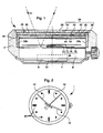
- This watch 1 conventionally comprises a box 2 provided with a bottom 4 in which are arranged an electronic clockwork movement 6 and a battery 8 which is supported on the bottom 4 by means of a contact spring 10.
- the movement 6 comprises associated electronic timekeeping circuits, via a control circuit, to a drive device (not shown) of a seconds hand 12, a minute hand 14 and an hour hand 16.
- These needles 12, 14 and 16 move over a dial 18 which carries index hours 20 visible on the figure 2 .
- the box 2 is also conventionally closed by an ice-cream 22 covering the entire dial 18.
- the watch 1 further comprises a display assembly comprising two superimposed display devices, respectively upper 24 and lower 26.
- the lower display device 26 comprises means for displaying the display. temporal quantities, in particular analog display means of the hour formed by the hands 12, 14, 16 and the dial 18.
- this lower display device 26 may be formed by any digital display device, for example of the liquid crystal type.
- This display device 26 may also comprise a combination of analog and digital display means such as the combination described in the patent.
- the upper display device 24 comprises a display cell 28 and extends between the lower display device 26 and the mirror 22. In the example shown, this upper display device 24 covers the entire surface of the dial 18. It goes without saying that, according to an alternative embodiment, the upper display device 24 can form the mirror 22 of the watch 1.
- the upper display device 24 is arranged so that the display cell 28 is transparent in a first switching state to make visible the information displayed by the lower display device 26, namely the hands 12, 14 and 16 and the dial 18.
- Such a configuration of the display assembly according to the invention is represented on the Figures 1 and 2 .
- the upper display device 24 is arranged so that the display cell 28 displays information, for example of the alphanumeric type, in a second switching state.
- Such a configuration of the display assembly according to the invention is represented on the Figures 3 and 4 .
- control means integrated in the movement 6, these control means being connected to the cell 28 via conventional connectors. 32a, 32b to provide a control voltage.
- the connectors 32a, 32b also form a flange disposed between the upper edge of the dial 18 and the lower edge of the cell 28.
- the cell 28 is a liquid crystal display cell of the diffusing or reflective type in the second switching state.
- the cell 28 is a liquid crystal cell of the nematic helical (TN) type.
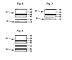
- This cell 28 comprises a transparent front substrate 34, a transparent rear substrate 36, and a sealing frame 38 forming spacing and closing means delimiting with the substrates 34 and 36 a cavity in which there is a layer of liquid crystals.
- the facing faces of the substrates 34 and 36 comprise transparent electrodes 40 and 42, made for example of indium / tin oxide.
- the front substrate 34 carries electrodes 40 configured in digits each formed of segments for displaying alphanumeric characters, while the rear substrate 36 carries an electrode 42 extending over its entire surface.
- the electrodes 40 and 42 are connected to the connector 32a through contact pads 44 located outside the cavity.
- the cell 28 further comprises, on the ice side 22, a linear polarizer 46 and, on the dial side 18, a quarter wave plate 48 associated with a cholesteric film 50.
- a cell is similar to the display device described in the publication of TJ Scheffer entitled “Twisted Nematic Display with Cholesteric Reflector” published in J. Phys. Appl. Phy., Vol. 8, 1975 which is quoted here for reference.
- the polarizer 46 is of the polarization efficiency and high transmission type such as, for example, the polarizer marketed by Sanritsu, Japan under the reference LLC25618SF.
- the switchable device 28 is advantageously transparent in the non-switched state, and reflecting in the switched state.
- the liquid crystals between these electrodes 40, 42 are passed alternately from a reflective or diffusing state to a transparent state. .
- the display cell 28 is a 90 ° twisted nematic type liquid crystal cell
- the polarizer 46 is of the conventional linear type
- the quarter wave plate 48 circularly polarises the light on the right
- the film cholesteric 50 is a left-handed propeller film.
- the cell 28 is completely transparent ( Figures 1 and 2 ) in the first switching state, i.e. when no voltage is applied across the electrodes 40, 42 (non-switched state). This state is symbolized by the ray of light R1 on the figure 1 where it is seen that it crosses the cell 28 and is reflected by the dial 18.
- the cell 28 is on the other hand reflective or diffusing in its switched regions ( Figures 3 and 4 ) in the second switching state, i.e.
- the polarizer 46 is rotated 90 ° with respect to its initial orientation. It should be noted that this same effect can also be obtained by rotating the quarter-wave plate 48 by 90 ° with respect to its initial orientation.
- the cell 28 is opaque and reflective when no control voltage is applied, and becomes transparent if a control voltage is applied between the electrodes 40, 42.
- the upper display device 24 further comprises a second quarter wave plate 52 placed immediately behind the cholesteric film 50
- the lower display device 26 comprises a dial 18 forming a metal reflector.
- the visible face of the dial 18 may comprise a reflective metal layer if the dial 18 is not made of metal, or this face may be polished if the dial 18 is metallic. Note that it is also possible to integrate the second quarter wave plate directly on the dial 18.
- the lower display device 26 comprises a dial 18 forming a cholesteric mirror having a helical direction opposite to that of said cholesteric film 50 of the upper display device 24.
- the lower display device 26 further comprises a second and a third quarter wave plates 54, 56 and a second cholesteric film 58 replacing the dial 18. It will also be possible to integrate the quarter wave plate 48 and the cholesteric film 50 in a single element such as, for example, the product TRANSMAX® marketed by Merck.
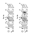
- any other polarizer reflecting one of the components of the linearly polarized light and transmitting the other component substantially perpendicular to the first can also be used behind the TN type cell 28 provided with a linear polarizer in front of the cell.
- a first state represented at figure 9a the linear polarizer 46 and the reflective polarizer 60 are oriented so as to have their axes of polarization crossed.
- a display cell 28 which is a positive-anisotropy helical nematic type liquid crystal cell placed between the two, the non-switched state of the cell 28 is completely transparent, so that the dial 18 is visible.
- the unpolarized natural light denoted by the numeral 62
- the polarization direction of the light denoted by the reference 64, is then rotated 90 ° as it passes through the display cell 28, then is transmitted without modification by the reflective polarizer 60 to the dial 18.
- the dial 18 is visible to an observer 66.
- the dial 18 is at least partially masked.
- the cell 28 is reflective or diffusing in its switched regions, that is to say in the areas in which the electrodes 40, 42 are switched.
- the vertically polarized light that passes through the cell 28 in the zones switched from the latter is not modified, so that it is reflected by the reflective polarizer 60.
- the light that passes through the cell 28 outside the switched areas is transmitted to the dial 18.
- the information are thus displayed in opaque on a transparent background, the opacity being determined by the color reflected by the reflective polarizer 60, and the background being determined by the color of the dial 18.
- figure 9b that the addressing of the cell 28 is normal, that is to say that the switched segments are those that we seek to actually display.
- the addressing of the display cell 28 may be inverse, that is to say that all the segments of said cell 28 are switched, to the exclusion of those which one seeks to display.
- the information is displayed in transparent on an opaque background, the transparency being, here also, determined by the color of the dial 18. It will be noted that turning the linear polarizer 46 by 90 °, one can obtain the opposite situation, i.e., the non-switched state is opaque, and the switched state is transparent.
- a second state represented at figure 10a the linear polarizer 46 and the reflective polarizer 60 are oriented so as to have their axes of polarization parallel.
- a display cell 28 which is a liquid crystal cell of the nematic type helically with negative anisotropy.
- the alignment of the liquid crystal molecules is therefore homeotropic in the non-switched state of said cell 28, so that the latter has no effect on the direction of polarization of the light in this state.
- the cell 28 is reflective or diffusing in its areas in which the electrodes 40 and 42 are switched.
- the dial 18 is thus partially masked, and the information appears to the observer 66 in opaque on a transparent background, the opacity being determined by the color reflected by the reflective polarizer 60, and the background being determined by the color of the dial 18.
- the addressing of the cell 28 is normal, that is to say that the switched segments are those that we seek to display. According to a variant not shown in the drawing, the addressing of the cell 28 can also be reversed.
- the information is then displayed in transparency on an opaque background, the transparency being determined by the color of the dial 18, and the background being determined by the color reflected by the reflective polarizer 60.
- the display assembly according to the invention therefore makes it possible, depending on the switching state and the type of the cell 28, to obtain different display configurations.
- the switching of the cell 28 can be carried out in a conventional manner, for example by means of switches controlled by one or more push-buttons (not shown in the drawing), each actuation of a push-button causing the switching of a state to a different state. other of the cell with which it is associated.
Landscapes
- Physics & Mathematics (AREA)
- General Physics & Mathematics (AREA)
- Nonlinear Science (AREA)
- Chemical & Material Sciences (AREA)
- Mathematical Physics (AREA)
- Crystallography & Structural Chemistry (AREA)
- Optics & Photonics (AREA)
- Dispersion Chemistry (AREA)
- Electric Clocks (AREA)
- Devices For Indicating Variable Information By Combining Individual Elements (AREA)
- Liquid Crystal (AREA)
Claims (8)
- Anzeigeanordnung, die zwei einander überlagerte Anzeigevorrichtungen umfasst, nämlich eine obere Anzeigevorrichtung (24) und eine untere Anzeigevorrichtung (26), wobei die obere Anzeigevorrichtung (24) eine Anzeigezelle (28), die so beschaffen ist, dass sie in einem ersten Zustand lichtdurchlässig ist, um die untere Anzeigevorrichtung (26) erkennbar zu machen, und so beschaffen ist, dass sie in einem zweiten Zustand eine Information anzeigt, und Steuermittel, die dazu ausgelegt sind, an die Zelle (28) eine Steuerspannung zu liefern, um sie von dem ersten Zustand in den zweiten Zustand und umgekehrt übergehen zu lassen umfasst, wobei die Zelle (28) eine Flüssigkristallanzeigezelle des streuenden oder reflektierenden Typs im zweiten Zustand ist, dadurch gekennzeichnet, dass sie eine Zelle (28) des schraubenlinienförmigen nematischen Typs ist, die versehen ist mit einem Linearpolarisator (46), der vor der Zelle (28) angeordnet ist, einem Viertelwellenlängenplättchen (48) und einer dünnen cholesterischen Schicht (50), die nacheinander hinter der Zelle (28) angeordnet sind, dass die obere Anzeigevorrichtung (24) oder die untere Anzeigevorrichtung (26) außerdem ein zweites Viertelwellenlängenplättchen (52) umfasst und dass die untere Anzeigevorrichtung (26) einen metallischen Reflektor umfasst, der hinter dem zweiten Viertelwellenlängenplättchen angeordnet ist.
- Anzeigeanordnung, die zwei einander überlagerte Anzeigevorrichtungen umfasst, nämlich eine obere Anzeigevorrichtung (24) und eine untere Anzeigevorrichtung (26), wobei die obere Anzeigevorrichtung (24) eine Anzeigezelle (28), die so beschaffen ist, dass sie in einem ersten Zustand lichtdurchlässig ist, um die untere Anzeigevorrichtung (26) erkennbar zu machen, und so beschaffen ist, dass sie in einem zweiten Zustand eine Information anzeigt, und Steuermittel, die dazu ausgelegt sind, an die Zelle (28) eine Steuerspannung zu liefern, um sie von dem ersten Zustand in den zweiten Zustand und umgekehrt übergehen zu lassen, umfasst, wobei die Zelle (28) eine Flüssigkristallanzeigezelle des streuenden oder reflektierenden Typs im zweiten Zustand ist, dadurch gekennzeichnet, dass sie eine Zelle (28) des schraubenlinienförmigen nematischen Typs umfasst, die versehen ist mit einem Linearpolarisator (46), der vor der Zelle (28) angeordnet ist, und mit einem Viertelwellenlängenplättchen (48), dem eine dünne cholestrische Schicht (50) mit einer ersten Schraubenlinienrichtung zugeordnet ist, die nacheinander hinter der Zelle (28) angeordnet sind, und dass die untere Anzeigevorrichtung (26) einen cholesterischen Spiegel mit einer Schraubenlinienrichtung, die zu jener der dünnen cholesterischen Schicht (50) entgegengesetzt ist, aufweist.
- Anzeigeanordnung, die zwei einander überlagerte Anzeigevorrichtungen umfasst, nämlich eine obere Anzeigevorrichtung (24) und eine untere Anzeigevorrichtung (26), wobei die obere Anzeigevorrichtung (24) eine Anzeigezelle (28), die so beschaffen ist, dass sie in einem ersten Zustand lichtdurchlässig ist, um die untere Anzeigevorrichtung (26) erkennbar zu machen, und so beschaffen ist, dass sie in einem zweiten Zustand eine Information anzeigt, und Steuermittel, die dazu ausgelegt sind, an die Zelle (28) eine Steuerspannung zu liefern, um sie von dem ersten Zustand in den zweiten Zustand und umgekehrt übergehen zu lassen, umfasst, wobei die Zelle (28) eine Flüssigkristallanzeigezelle des streuenden oder reflektierenden Typs im zweiten Zustand ist, dadurch gekennzeichnet, dass sie eine Zelle (28) des schraubenlinienförmigen nematischen Typs umfasst, die versehen ist mit einem Linearpolarisator (46), der vor der Zelle (28) angeordnet ist, und einem Viertelwellenlängenplättchen (48), dem eine dünne cholesterische Schicht (50) zugeordnet ist, die nacheinander hinter der Zelle (28) angeordnet sind, und dass die untere Anzeigevorrichtung (26) außerdem ein Halbwellenlängenplättchen und eine zweite dünne cholesterische Schicht (58), die wie die erste beschaffen ist, umfasst.
- Anzeigeanordnung nach einem der Ansprüche 1 bis 3, dadurch gekennzeichnet, dass die Zelle (28) im ersten Zustand bei Abwesenheit einer durch die Steuermittel angelegten Spannung lichtdurchlässig ist.
- Anzeigeanordnung nach einem der vorhergehenden Ansprüche, dadurch gekennzeichnet, dass die untere Anzeigevorrichtung (26) eine Anzeigevorrichtung ist, die aus der Gruppe gewählt ist, die durch analoge Vorrichtungen, digitale Vorrichtungen und eine Kombination aus diesen Letzteren und/oder aus einem verzierenden Element gebildet ist.
- Zeitmessgerät, das ein durch ein Uhrenglas (22) und einen Boden (4) verschlossenes Gehäuse (2) umfasst, in dem ein Uhrwerk (6) angeordnet ist, dem eine Vorrichtung für die Anzeige zeitlicher Größen zugeordnet ist, dadurch gekennzeichnet, dass es eine Anzeigeanordnung nach einem der Ansprüche 1 bis 5 umfasst, wobei die untere Anzeigevorrichtung (26) durch die Vorrichtung zum Anzeigen zeitlicher Größen gebildet ist und die obere Anzeigevorrichtung (24) sich zwischen dem Uhrenglas (22) und der Vorrichtung zum Anzeigen zeitlicher Größen erstreckt.
- Zeitmessgerät nach Anspruch 6, dadurch gekennzeichnet, dass die Vorrichtung zum Anzeigen zeitlicher Größen ein Zifferblatt (18), einen Stundenzeiger (16) und einen Minutenzeiger (24), die sich auf dem Zifferblatt (18) verlagern, umfasst.
- Zeitmessgerät nach einem der Ansprüche 6 oder 7, dadurch gekennzeichnet, dass das Uhrenglas (22) durch die obere Anzeigevorrichtung (24) gebildet ist.
Priority Applications (1)
| Application Number | Priority Date | Filing Date | Title |
|---|---|---|---|
| EP99103395A EP0939331B1 (de) | 1998-02-27 | 1999-02-22 | Anzeigeeinheit mit zwei aufeinander liegenden Anzeigevorrichtungen |
Applications Claiming Priority (5)
| Application Number | Priority Date | Filing Date | Title |
|---|---|---|---|
| CH46698 | 1998-02-27 | ||
| CH46698 | 1998-02-27 | ||
| EP98103611 | 1998-03-02 | ||
| EP98103611 | 1998-03-02 | ||
| EP99103395A EP0939331B1 (de) | 1998-02-27 | 1999-02-22 | Anzeigeeinheit mit zwei aufeinander liegenden Anzeigevorrichtungen |
Publications (3)
| Publication Number | Publication Date |
|---|---|
| EP0939331A2 EP0939331A2 (de) | 1999-09-01 |
| EP0939331A3 EP0939331A3 (de) | 2000-04-19 |
| EP0939331B1 true EP0939331B1 (de) | 2010-04-14 |
Family
ID=27172130
Family Applications (1)
| Application Number | Title | Priority Date | Filing Date |
|---|---|---|---|
| EP99103395A Expired - Lifetime EP0939331B1 (de) | 1998-02-27 | 1999-02-22 | Anzeigeeinheit mit zwei aufeinander liegenden Anzeigevorrichtungen |
Country Status (1)
| Country | Link |
|---|---|
| EP (1) | EP0939331B1 (de) |
Families Citing this family (7)
| Publication number | Priority date | Publication date | Assignee | Title |
|---|---|---|---|---|
| TW565812B (en) | 2000-07-21 | 2003-12-11 | Ebauchesfabrik Eta Ag | Display assembly including an electro-optical cell and a photovoltaic cell |
| EP1213631A1 (de) * | 2000-12-11 | 2002-06-12 | Eta SA Fabriques d'Ebauches | Verfahren zum sequentielen Ansteuern einer Anzeigevorrichtung die zwei übereinander liegende Anzeigemittel umfasst |
| US6671231B2 (en) | 2000-12-11 | 2003-12-30 | Eta Sa Fabriques D'ebauches | Sequential control method for a display assembly including two superposed display devices |
| JP2004271259A (ja) * | 2003-03-06 | 2004-09-30 | Casio Comput Co Ltd | 時計モジュール |
| US20150241852A1 (en) * | 2014-02-27 | 2015-08-27 | Sun Jong YANG | Mechanical/quartz movement smart watch hybrid |
| CH711345A1 (fr) | 2015-07-21 | 2017-01-31 | Soprod Sa | Système multifonctions comprenant une montre avec un affichage mécanique et électro-optique. |
| EP3839617B1 (de) * | 2019-12-17 | 2024-06-26 | The Swatch Group Research and Development Ltd | Flüssigkristall-anzeigevorrichtung |
Family Cites Families (9)
| Publication number | Priority date | Publication date | Assignee | Title |
|---|---|---|---|---|
| IT7953449U1 (it) | 1979-07-26 | 1981-01-26 | Fiat Auto Spa | Sospensione per autoveicoli a ruote motrici e sterzanti. |
| CH642227B (fr) | 1981-10-28 | Asulab Sa | Montre a dispositif d'affichage analogique dont le cadran est forme par une cellule d'affichage a cristal liquide. | |
| DE69228843T2 (de) * | 1991-05-27 | 1999-08-26 | Dainippon Ink And Chemicals | Flüssigkristallvorrichtung |
| JP3268858B2 (ja) * | 1992-11-30 | 2002-03-25 | 三洋電機株式会社 | 液晶表示装置 |
| WO1994023331A1 (fr) * | 1993-03-29 | 1994-10-13 | Seiko Epson Corporation | Dispositif d'affichage et appareil electronique |
| JPH08201547A (ja) * | 1995-01-30 | 1996-08-09 | Casio Comput Co Ltd | 液晶表示装置を備えた電子機器 |
| JP2998075B2 (ja) * | 1996-06-20 | 2000-01-11 | セイコーインスツルメンツ株式会社 | 反射型液晶表示装置 |
| JP3331903B2 (ja) * | 1996-08-23 | 2002-10-07 | セイコーエプソン株式会社 | 表示素子及びそれを用いた電子機器 |
| KR100334843B1 (ko) * | 1997-07-18 | 2002-05-04 | 하루타 히로시 | 시계 |
-
1999
- 1999-02-22 EP EP99103395A patent/EP0939331B1/de not_active Expired - Lifetime
Also Published As
| Publication number | Publication date |
|---|---|
| EP0939331A2 (de) | 1999-09-01 |
| EP0939331A3 (de) | 2000-04-19 |
Similar Documents
| Publication | Publication Date | Title |
|---|---|---|
| EP1040391B1 (de) | Anzeigeeinheit mit zwei übereinander liegenden anzeigevorrichtungen | |
| EP0078237B1 (de) | Uhr mit analoger Anzeige, deren Zifferblatt aus einer Flüssigkeitskristallanzeigezelle besteht | |
| US6515942B2 (en) | Display assembly including two superposed display devices | |
| EP1128240A1 (de) | Eine zwei übereinander angeordnete Anzeigevorrichtungen umfassende Anzeigeeinheit mit Kontrastinversion | |
| US6587083B1 (en) | Display assembly including two superposed display devices | |
| EP0786685A1 (de) | Verzierung anzeigende Vorrichtung und diese enthaltende Uhr | |
| WO1999004322A1 (en) | Watch | |
| FR2496289A1 (fr) | Montre ayant un affichage analogique et un affichage numerique | |
| EP1780616A2 (de) | Anzeigeanordnung mit dekorativen Effekten für ein tragbares Instrument, wie eine Uhr | |
| EP3650958B1 (de) | Gegenstand, der mit einer elektrooptischen anzeigevorrichtung ausgestattet ist | |
| HK1047481A1 (en) | Sequential control method for a display assembly including two superposed display devices | |
| WO2007096358A1 (fr) | Dispositif d'affichage à cristaux liquides affichant des segments colorés et pièce d'horlogerie équipée de ce dispositif | |
| EP0939331B1 (de) | Anzeigeeinheit mit zwei aufeinander liegenden Anzeigevorrichtungen | |
| EP3839617B1 (de) | Flüssigkristall-anzeigevorrichtung | |
| EP1626316B1 (de) | Uhr mit Lichtleiternuhrenglas | |
| EP0926574A1 (de) | Anzeigekombination mit zwei übereinander gestellten Anzeigevorrichtungen | |
| EP1189095A1 (de) | Zweifarbige Flüssigkristallanzeigeeinheit | |
| EP1085364B1 (de) | Anzeigeeinheit mit zwei übereinander angeordneten Anzeigenvorrichtungen | |
| EP1174756B1 (de) | Anzeigeeinheit mit einer elektrooptischen und einer photovoltaischen Zelle | |
| EP1213631A1 (de) | Verfahren zum sequentielen Ansteuern einer Anzeigevorrichtung die zwei übereinander liegende Anzeigemittel umfasst | |
| EP1156360B1 (de) | Anzeigeeinheit mit chromatischer Kontrastumkehrung | |
| JPH1123738A (ja) | 太陽電池を備える時計 | |
| JP4252124B2 (ja) | 時計 | |
| CH715286B1 (fr) | Objet muni d'un dispositif d`affichage électrooptique. | |
| EP1202109A1 (de) | Flüssigkristallanzeigeeinrichtung mit hohem Reflexionskoeffizienten |
Legal Events
| Date | Code | Title | Description |
|---|---|---|---|
| PUAI | Public reference made under article 153(3) epc to a published international application that has entered the european phase |
Free format text: ORIGINAL CODE: 0009012 |
|
| AK | Designated contracting states |
Kind code of ref document: A2 Designated state(s): CH DE ES FR GB IT LI NL |
|
| AX | Request for extension of the european patent |
Free format text: AL;LT;LV;MK;RO;SI |
|
| PUAL | Search report despatched |
Free format text: ORIGINAL CODE: 0009013 |
|
| AK | Designated contracting states |
Kind code of ref document: A3 Designated state(s): AT BE CH CY DE DK ES FI FR GB GR IE IT LI LU MC NL PT SE |
|
| AX | Request for extension of the european patent |
Free format text: AL;LT;LV;MK;RO;SI |
|
| RIC1 | Information provided on ipc code assigned before grant |
Free format text: 7G 04G 9/00 A, 7G 02F 1/1333 B, 7G 02F 1/1335 B |
|
| 17P | Request for examination filed |
Effective date: 20001019 |
|
| AKX | Designation fees paid |
Free format text: CH DE ES FR GB IT LI NL |
|
| 17Q | First examination report despatched |
Effective date: 20080218 |
|
| RAP1 | Party data changed (applicant data changed or rights of an application transferred) |
Owner name: ASULAB S.A. |
|
| GRAP | Despatch of communication of intention to grant a patent |
Free format text: ORIGINAL CODE: EPIDOSNIGR1 |
|
| RIC1 | Information provided on ipc code assigned before grant |
Ipc: G04G 9/00 20060101ALI20091112BHEP Ipc: G04C 17/00 20060101AFI20091112BHEP |
|
| GRAS | Grant fee paid |
Free format text: ORIGINAL CODE: EPIDOSNIGR3 |
|
| GRAA | (expected) grant |
Free format text: ORIGINAL CODE: 0009210 |
|
| AK | Designated contracting states |
Kind code of ref document: B1 Designated state(s): CH DE ES FR GB IT LI NL |
|
| REG | Reference to a national code |
Ref country code: GB Ref legal event code: FG4D Free format text: NOT ENGLISH |
|
| REG | Reference to a national code |
Ref country code: CH Ref legal event code: EP |
|
| REG | Reference to a national code |
Ref country code: CH Ref legal event code: NV Representative=s name: ICB INGENIEURS CONSEILS EN BREVETS SA |
|
| REF | Corresponds to: |
Ref document number: 69942242 Country of ref document: DE Date of ref document: 20100527 Kind code of ref document: P |
|
| REG | Reference to a national code |
Ref country code: NL Ref legal event code: VDEP Effective date: 20100414 |
|
| PG25 | Lapsed in a contracting state [announced via postgrant information from national office to epo] |
Ref country code: NL Free format text: LAPSE BECAUSE OF FAILURE TO SUBMIT A TRANSLATION OF THE DESCRIPTION OR TO PAY THE FEE WITHIN THE PRESCRIBED TIME-LIMIT Effective date: 20100414 Ref country code: ES Free format text: LAPSE BECAUSE OF FAILURE TO SUBMIT A TRANSLATION OF THE DESCRIPTION OR TO PAY THE FEE WITHIN THE PRESCRIBED TIME-LIMIT Effective date: 20100725 |
|
| PLBE | No opposition filed within time limit |
Free format text: ORIGINAL CODE: 0009261 |
|
| STAA | Information on the status of an ep patent application or granted ep patent |
Free format text: STATUS: NO OPPOSITION FILED WITHIN TIME LIMIT |
|
| 26N | No opposition filed |
Effective date: 20110117 |
|
| PG25 | Lapsed in a contracting state [announced via postgrant information from national office to epo] |
Ref country code: IT Free format text: LAPSE BECAUSE OF FAILURE TO SUBMIT A TRANSLATION OF THE DESCRIPTION OR TO PAY THE FEE WITHIN THE PRESCRIBED TIME-LIMIT Effective date: 20100414 |
|
| GBPC | Gb: european patent ceased through non-payment of renewal fee |
Effective date: 20110222 |
|
| PG25 | Lapsed in a contracting state [announced via postgrant information from national office to epo] |
Ref country code: GB Free format text: LAPSE BECAUSE OF NON-PAYMENT OF DUE FEES Effective date: 20110222 |
|
| REG | Reference to a national code |
Ref country code: FR Ref legal event code: PLFP Year of fee payment: 18 |
|
| REG | Reference to a national code |
Ref country code: FR Ref legal event code: PLFP Year of fee payment: 19 |
|
| PGFP | Annual fee paid to national office [announced via postgrant information from national office to epo] |
Ref country code: FR Payment date: 20170124 Year of fee payment: 19 Ref country code: DE Payment date: 20170119 Year of fee payment: 19 |
|
| PGFP | Annual fee paid to national office [announced via postgrant information from national office to epo] |
Ref country code: CH Payment date: 20180129 Year of fee payment: 20 |
|
| REG | Reference to a national code |
Ref country code: DE Ref legal event code: R119 Ref document number: 69942242 Country of ref document: DE |
|
| REG | Reference to a national code |
Ref country code: FR Ref legal event code: ST Effective date: 20181031 |
|
| PG25 | Lapsed in a contracting state [announced via postgrant information from national office to epo] |
Ref country code: DE Free format text: LAPSE BECAUSE OF NON-PAYMENT OF DUE FEES Effective date: 20180901 |
|
| PG25 | Lapsed in a contracting state [announced via postgrant information from national office to epo] |
Ref country code: FR Free format text: LAPSE BECAUSE OF NON-PAYMENT OF DUE FEES Effective date: 20180228 |
|
| REG | Reference to a national code |
Ref country code: CH Ref legal event code: PL |