EP0939331B1 - Display unit comprising two superposed display devices - Google Patents
Display unit comprising two superposed display devices Download PDFInfo
- Publication number
- EP0939331B1 EP0939331B1 EP99103395A EP99103395A EP0939331B1 EP 0939331 B1 EP0939331 B1 EP 0939331B1 EP 99103395 A EP99103395 A EP 99103395A EP 99103395 A EP99103395 A EP 99103395A EP 0939331 B1 EP0939331 B1 EP 0939331B1
- Authority
- EP
- European Patent Office
- Prior art keywords
- cell
- display device
- display
- state
- dial
- Prior art date
- Legal status (The legal status is an assumption and is not a legal conclusion. Google has not performed a legal analysis and makes no representation as to the accuracy of the status listed.)
- Expired - Lifetime
Links
Images


Classifications
-
- G—PHYSICS
- G02—OPTICS
- G02F—OPTICAL DEVICES OR ARRANGEMENTS FOR THE CONTROL OF LIGHT BY MODIFICATION OF THE OPTICAL PROPERTIES OF THE MEDIA OF THE ELEMENTS INVOLVED THEREIN; NON-LINEAR OPTICS; FREQUENCY-CHANGING OF LIGHT; OPTICAL LOGIC ELEMENTS; OPTICAL ANALOGUE/DIGITAL CONVERTERS
- G02F1/00—Devices or arrangements for the control of the intensity, colour, phase, polarisation or direction of light arriving from an independent light source, e.g. switching, gating or modulating; Non-linear optics
- G02F1/01—Devices or arrangements for the control of the intensity, colour, phase, polarisation or direction of light arriving from an independent light source, e.g. switching, gating or modulating; Non-linear optics for the control of the intensity, phase, polarisation or colour
- G02F1/13—Devices or arrangements for the control of the intensity, colour, phase, polarisation or direction of light arriving from an independent light source, e.g. switching, gating or modulating; Non-linear optics for the control of the intensity, phase, polarisation or colour based on liquid crystals, e.g. single liquid crystal display cells
- G02F1/133—Constructional arrangements; Operation of liquid crystal cells; Circuit arrangements
- G02F1/1333—Constructional arrangements; Manufacturing methods
- G02F1/1335—Structural association of cells with optical devices, e.g. polarisers or reflectors
- G02F1/133528—Polarisers
- G02F1/133536—Reflective polarizers
-
- G—PHYSICS
- G02—OPTICS
- G02F—OPTICAL DEVICES OR ARRANGEMENTS FOR THE CONTROL OF LIGHT BY MODIFICATION OF THE OPTICAL PROPERTIES OF THE MEDIA OF THE ELEMENTS INVOLVED THEREIN; NON-LINEAR OPTICS; FREQUENCY-CHANGING OF LIGHT; OPTICAL LOGIC ELEMENTS; OPTICAL ANALOGUE/DIGITAL CONVERTERS
- G02F1/00—Devices or arrangements for the control of the intensity, colour, phase, polarisation or direction of light arriving from an independent light source, e.g. switching, gating or modulating; Non-linear optics
- G02F1/01—Devices or arrangements for the control of the intensity, colour, phase, polarisation or direction of light arriving from an independent light source, e.g. switching, gating or modulating; Non-linear optics for the control of the intensity, phase, polarisation or colour
- G02F1/13—Devices or arrangements for the control of the intensity, colour, phase, polarisation or direction of light arriving from an independent light source, e.g. switching, gating or modulating; Non-linear optics for the control of the intensity, phase, polarisation or colour based on liquid crystals, e.g. single liquid crystal display cells
- G02F1/133—Constructional arrangements; Operation of liquid crystal cells; Circuit arrangements
- G02F1/1333—Constructional arrangements; Manufacturing methods
- G02F1/1334—Constructional arrangements; Manufacturing methods based on polymer dispersed liquid crystals, e.g. microencapsulated liquid crystals
-
- G—PHYSICS
- G04—HOROLOGY
- G04C—ELECTROMECHANICAL CLOCKS OR WATCHES
- G04C17/00—Indicating the time optically by electric means
- G04C17/0091—Combined electro-optical and electro-mechanical displays
-
- G—PHYSICS
- G04—HOROLOGY
- G04G—ELECTRONIC TIME-PIECES
- G04G9/00—Visual time or date indication means
- G04G9/0082—Visual time or date indication means by building-up characters using a combination of indicating elements and by selecting desired characters out of a number of characters or by selecting indicating elements the positions of which represents the time, i.e. combinations of G04G9/02 and G04G9/08
-
- G—PHYSICS
- G02—OPTICS
- G02F—OPTICAL DEVICES OR ARRANGEMENTS FOR THE CONTROL OF LIGHT BY MODIFICATION OF THE OPTICAL PROPERTIES OF THE MEDIA OF THE ELEMENTS INVOLVED THEREIN; NON-LINEAR OPTICS; FREQUENCY-CHANGING OF LIGHT; OPTICAL LOGIC ELEMENTS; OPTICAL ANALOGUE/DIGITAL CONVERTERS
- G02F1/00—Devices or arrangements for the control of the intensity, colour, phase, polarisation or direction of light arriving from an independent light source, e.g. switching, gating or modulating; Non-linear optics
- G02F1/01—Devices or arrangements for the control of the intensity, colour, phase, polarisation or direction of light arriving from an independent light source, e.g. switching, gating or modulating; Non-linear optics for the control of the intensity, phase, polarisation or colour
- G02F1/13—Devices or arrangements for the control of the intensity, colour, phase, polarisation or direction of light arriving from an independent light source, e.g. switching, gating or modulating; Non-linear optics for the control of the intensity, phase, polarisation or colour based on liquid crystals, e.g. single liquid crystal display cells
- G02F1/133—Constructional arrangements; Operation of liquid crystal cells; Circuit arrangements
- G02F1/1333—Constructional arrangements; Manufacturing methods
- G02F1/1335—Structural association of cells with optical devices, e.g. polarisers or reflectors
- G02F1/133528—Polarisers
- G02F1/133543—Cholesteric polarisers
Definitions
- the present invention relates to a display assembly comprising at least two superposed display devices, and more particularly to a timepiece comprising a display assembly of this type in which an analog display device is combined with a display device. 'digital display.
- an electronic watch comprising a box in which are provided both an analog display device and a digital display device.
- the analog display device includes an hour hand and a minute hand that move conventionally over a dial, while the digital display device includes a transparent liquid crystal cell disposed in front of the display device. analog display that it completely covers.
- the digital display device allows the display of alphanumeric characters, for example the day of the week and the date in dark on a light background.
- the liquid crystal cell forms the ice of the watch. It is a liquid crystal cell of the helical nematic type comprising two polarizers arranged on either side of the cell, the dial which is located under the cell being used as a reflector.
- the reflector and therefore the dial of the watch, must reflect the incident light without changing its polarization to produce a brilliant and contrasted display.
- This display device therefore limits the type of dial that can be used to form the lower display device, especially when the lower device is a digital display device. In in this case, only dials having non-diffusing reflection properties, ie metallic reflectors, can be used.
- this type of cell usually displays information in dark on a light background, which excludes the use of dark dials as reflectors.
- the bright background actually appears rather greyish due to the absorption of a significant amount of light by the polarizers, which gives the display device readability and brightness unsatisfactory.
- the reflection of the light is on the dial, and therefore at a distance from the cell, typically 2 to 3 mm, the images of the switched segments of the cell appear in projection on the dial, which leads to optical splitting of the displayed information. This affects not only the aesthetics of the watch, but also, of course, the readability of the information displayed.
- EP0643318 discloses an electronic device comprising two superimposed display devices.
- the upper display device comprises a PDLC cell and is arranged to be made transparent to light or alternatively to hide at least a portion of the lower display.
- the object of the present invention is to overcome the drawbacks of the aforementioned prior art by proposing a display assembly comprising at least two superimposed display devices, respectively lower and upper, in which the brightness of the information displayed by the device of FIG. superior display and therefore their readability, are little or not dependent on the nature (diffusing / reflective) of the dial of the lower display and its color (light or dark).
- the present invention also aims to provide a timepiece equipped with such a display assembly having an improved aesthetic appearance.
- the subject of the invention is a display assembly as defined in claim 1.
- the passage of light through the second quarter-wave plate transforms the circular polarized light from the cholesteric film into linear polarized light for which the metal reflector is more efficient.
- This structure makes it possible to homogenise the light reflected by the display assembly and to make the color of the latter less dependent on the wavelength of the light
- the subject of the invention is a display assembly as defined in claim 2. provided with a polarizer placed in front of the cell, and a quarter-wave plate associated with a cholesteric film having a first helical direction, placed successively behind the cell, the lower display device comprising a cholesteric mirror having a reverse helix direction to that of said cholesteric film.
- the cholesteric mirror may advantageously form the dial of the watch. Another advantage of this structure lies in the fact that one can choose cholesteric mirrors of different colors, which makes it possible to produce colored display sets.
- the subject of the invention is a display assembly as defined in claim 3.
- the display cell is in a transparent state in the absence of voltage applied by the control means.
- the information displayed by the lower display device is thus permanently visible, without the upper display device consuming energy. This is particularly advantageous in the context of the application of this display assembly to a portable object such as a wristwatch.
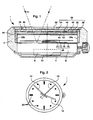
- This watch 1 conventionally comprises a box 2 provided with a bottom 4 in which are arranged an electronic clockwork movement 6 and a battery 8 which is supported on the bottom 4 by means of a contact spring 10.
- the movement 6 comprises associated electronic timekeeping circuits, via a control circuit, to a drive device (not shown) of a seconds hand 12, a minute hand 14 and an hour hand 16.
- These needles 12, 14 and 16 move over a dial 18 which carries index hours 20 visible on the figure 2 .
- the box 2 is also conventionally closed by an ice-cream 22 covering the entire dial 18.
- the watch 1 further comprises a display assembly comprising two superimposed display devices, respectively upper 24 and lower 26.
- the lower display device 26 comprises means for displaying the display. temporal quantities, in particular analog display means of the hour formed by the hands 12, 14, 16 and the dial 18.
- this lower display device 26 may be formed by any digital display device, for example of the liquid crystal type.
- This display device 26 may also comprise a combination of analog and digital display means such as the combination described in the patent.
- the upper display device 24 comprises a display cell 28 and extends between the lower display device 26 and the mirror 22. In the example shown, this upper display device 24 covers the entire surface of the dial 18. It goes without saying that, according to an alternative embodiment, the upper display device 24 can form the mirror 22 of the watch 1.
- the upper display device 24 is arranged so that the display cell 28 is transparent in a first switching state to make visible the information displayed by the lower display device 26, namely the hands 12, 14 and 16 and the dial 18.
- Such a configuration of the display assembly according to the invention is represented on the Figures 1 and 2 .
- the upper display device 24 is arranged so that the display cell 28 displays information, for example of the alphanumeric type, in a second switching state.
- Such a configuration of the display assembly according to the invention is represented on the Figures 3 and 4 .
- control means integrated in the movement 6, these control means being connected to the cell 28 via conventional connectors. 32a, 32b to provide a control voltage.
- the connectors 32a, 32b also form a flange disposed between the upper edge of the dial 18 and the lower edge of the cell 28.
- the cell 28 is a liquid crystal display cell of the diffusing or reflective type in the second switching state.
- the cell 28 is a liquid crystal cell of the nematic helical (TN) type.
- This cell 28 comprises a transparent front substrate 34, a transparent rear substrate 36, and a sealing frame 38 forming spacing and closing means delimiting with the substrates 34 and 36 a cavity in which there is a layer of liquid crystals.
- the facing faces of the substrates 34 and 36 comprise transparent electrodes 40 and 42, made for example of indium / tin oxide.
- the front substrate 34 carries electrodes 40 configured in digits each formed of segments for displaying alphanumeric characters, while the rear substrate 36 carries an electrode 42 extending over its entire surface.
- the electrodes 40 and 42 are connected to the connector 32a through contact pads 44 located outside the cavity.
- the cell 28 further comprises, on the ice side 22, a linear polarizer 46 and, on the dial side 18, a quarter wave plate 48 associated with a cholesteric film 50.
- a cell is similar to the display device described in the publication of TJ Scheffer entitled “Twisted Nematic Display with Cholesteric Reflector” published in J. Phys. Appl. Phy., Vol. 8, 1975 which is quoted here for reference.
- the polarizer 46 is of the polarization efficiency and high transmission type such as, for example, the polarizer marketed by Sanritsu, Japan under the reference LLC25618SF.
- the switchable device 28 is advantageously transparent in the non-switched state, and reflecting in the switched state.
- the liquid crystals between these electrodes 40, 42 are passed alternately from a reflective or diffusing state to a transparent state. .
- the display cell 28 is a 90 ° twisted nematic type liquid crystal cell
- the polarizer 46 is of the conventional linear type
- the quarter wave plate 48 circularly polarises the light on the right
- the film cholesteric 50 is a left-handed propeller film.
- the cell 28 is completely transparent ( Figures 1 and 2 ) in the first switching state, i.e. when no voltage is applied across the electrodes 40, 42 (non-switched state). This state is symbolized by the ray of light R1 on the figure 1 where it is seen that it crosses the cell 28 and is reflected by the dial 18.
- the cell 28 is on the other hand reflective or diffusing in its switched regions ( Figures 3 and 4 ) in the second switching state, i.e.
- the polarizer 46 is rotated 90 ° with respect to its initial orientation. It should be noted that this same effect can also be obtained by rotating the quarter-wave plate 48 by 90 ° with respect to its initial orientation.
- the cell 28 is opaque and reflective when no control voltage is applied, and becomes transparent if a control voltage is applied between the electrodes 40, 42.
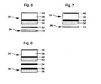
- the upper display device 24 further comprises a second quarter wave plate 52 placed immediately behind the cholesteric film 50
- the lower display device 26 comprises a dial 18 forming a metal reflector.
- the visible face of the dial 18 may comprise a reflective metal layer if the dial 18 is not made of metal, or this face may be polished if the dial 18 is metallic. Note that it is also possible to integrate the second quarter wave plate directly on the dial 18.
- the lower display device 26 comprises a dial 18 forming a cholesteric mirror having a helical direction opposite to that of said cholesteric film 50 of the upper display device 24.
- the lower display device 26 further comprises a second and a third quarter wave plates 54, 56 and a second cholesteric film 58 replacing the dial 18. It will also be possible to integrate the quarter wave plate 48 and the cholesteric film 50 in a single element such as, for example, the product TRANSMAX® marketed by Merck.
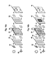
- any other polarizer reflecting one of the components of the linearly polarized light and transmitting the other component substantially perpendicular to the first can also be used behind the TN type cell 28 provided with a linear polarizer in front of the cell.
- a first state represented at figure 9a the linear polarizer 46 and the reflective polarizer 60 are oriented so as to have their axes of polarization crossed.
- a display cell 28 which is a positive-anisotropy helical nematic type liquid crystal cell placed between the two, the non-switched state of the cell 28 is completely transparent, so that the dial 18 is visible.
- the unpolarized natural light denoted by the numeral 62
- the polarization direction of the light denoted by the reference 64, is then rotated 90 ° as it passes through the display cell 28, then is transmitted without modification by the reflective polarizer 60 to the dial 18.
- the dial 18 is visible to an observer 66.
- the dial 18 is at least partially masked.
- the cell 28 is reflective or diffusing in its switched regions, that is to say in the areas in which the electrodes 40, 42 are switched.
- the vertically polarized light that passes through the cell 28 in the zones switched from the latter is not modified, so that it is reflected by the reflective polarizer 60.
- the light that passes through the cell 28 outside the switched areas is transmitted to the dial 18.
- the information are thus displayed in opaque on a transparent background, the opacity being determined by the color reflected by the reflective polarizer 60, and the background being determined by the color of the dial 18.
- figure 9b that the addressing of the cell 28 is normal, that is to say that the switched segments are those that we seek to actually display.
- the addressing of the display cell 28 may be inverse, that is to say that all the segments of said cell 28 are switched, to the exclusion of those which one seeks to display.
- the information is displayed in transparent on an opaque background, the transparency being, here also, determined by the color of the dial 18. It will be noted that turning the linear polarizer 46 by 90 °, one can obtain the opposite situation, i.e., the non-switched state is opaque, and the switched state is transparent.
- a second state represented at figure 10a the linear polarizer 46 and the reflective polarizer 60 are oriented so as to have their axes of polarization parallel.
- a display cell 28 which is a liquid crystal cell of the nematic type helically with negative anisotropy.
- the alignment of the liquid crystal molecules is therefore homeotropic in the non-switched state of said cell 28, so that the latter has no effect on the direction of polarization of the light in this state.
- the cell 28 is reflective or diffusing in its areas in which the electrodes 40 and 42 are switched.
- the dial 18 is thus partially masked, and the information appears to the observer 66 in opaque on a transparent background, the opacity being determined by the color reflected by the reflective polarizer 60, and the background being determined by the color of the dial 18.
- the addressing of the cell 28 is normal, that is to say that the switched segments are those that we seek to display. According to a variant not shown in the drawing, the addressing of the cell 28 can also be reversed.
- the information is then displayed in transparency on an opaque background, the transparency being determined by the color of the dial 18, and the background being determined by the color reflected by the reflective polarizer 60.
- the display assembly according to the invention therefore makes it possible, depending on the switching state and the type of the cell 28, to obtain different display configurations.
- the switching of the cell 28 can be carried out in a conventional manner, for example by means of switches controlled by one or more push-buttons (not shown in the drawing), each actuation of a push-button causing the switching of a state to a different state. other of the cell with which it is associated.
Landscapes
- Physics & Mathematics (AREA)
- General Physics & Mathematics (AREA)
- Nonlinear Science (AREA)
- Chemical & Material Sciences (AREA)
- Mathematical Physics (AREA)
- Crystallography & Structural Chemistry (AREA)
- Optics & Photonics (AREA)
- Dispersion Chemistry (AREA)
- Electric Clocks (AREA)
- Liquid Crystal (AREA)
- Devices For Indicating Variable Information By Combining Individual Elements (AREA)
Description
La présente invention concerne un ensemble d'affichage comprenant au moins deux dispositifs d'affichage superposés, et plus particulièrement une pièce d'horlogerie comprenant un ensemble d'affichage de ce type dans lequel un dispositif d'affichage analogique est combiné à un dispositif d'affichage numérique.The present invention relates to a display assembly comprising at least two superposed display devices, and more particularly to a timepiece comprising a display assembly of this type in which an analog display device is combined with a display device. 'digital display.
On connaît déjà par le brevet
Par ailleurs, ce type de cellule affiche généralement les informations en foncé sur fond clair, ce qui exclut l'utilisation de cadrans foncés comme réflecteurs. De plus, le fond clair apparaît en réalité plutôt grisâtre en raison de l'absorption d'une quantité non négligeable de lumière par les polariseurs, ce qui confère au dispositif d'affichage une lisibilité et une luminosité peu satisfaisantes.In addition, this type of cell usually displays information in dark on a light background, which excludes the use of dark dials as reflectors. In addition, the bright background actually appears rather greyish due to the absorption of a significant amount of light by the polarizers, which gives the display device readability and brightness unsatisfactory.
Une telle limitation dans le choix des cadrans représente un inconvénient important pour les fabricants de montres qui souhaitent pouvoir mettre sur le marché des montres comportant des cadrans de tout type pour s'adapter aux évolutions de la mode.Such a limitation in the choice of dials represents a significant disadvantage for watch manufacturers who wish to be able to market watches with dials of any type to adapt to changing fashion.
En outre, comme la réflexion de la lumière se fait sur le cadran, et donc à une certaine distance de la cellule, typiquement 2 à 3 mm, les images des segments commutés de la cellule apparaissent en projection sur le cadran, ce qui conduit au dédoublement optique de l'information affichée. Ceci nuit non seulement à l'esthétique de la montre, mais aussi, bien sûr, à la lisibilité de l'information affichée.In addition, as the reflection of the light is on the dial, and therefore at a distance from the cell, typically 2 to 3 mm, the images of the switched segments of the cell appear in projection on the dial, which leads to optical splitting of the displayed information. This affects not only the aesthetics of the watch, but also, of course, the readability of the information displayed.
La présente invention a pour but de remédier aux inconvénients de l'art antérieur susmentionnés en proposant un ensemble d'affichage comportant au moins deux dispositifs d'affichage superposés, respectivement inférieur et supérieur, dans lequel la luminosité des informations affichées par le dispositif d'affichage supérieur et donc leur lisibilité, sont peu ou pas dépendantes de la nature (diffusant/réfléchissant) du cadran de l'affichage inférieur et de sa couleur (claire ou foncée).The object of the present invention is to overcome the drawbacks of the aforementioned prior art by proposing a display assembly comprising at least two superimposed display devices, respectively lower and upper, in which the brightness of the information displayed by the device of FIG. superior display and therefore their readability, are little or not dependent on the nature (diffusing / reflective) of the dial of the lower display and its color (light or dark).
La présente invention a également pour but de fournir un ensemble d'affichage dans lequel le dispositif d'affichage supérieur est un dispositif à cristaux liquides présentant un contraste d'affichage amélioré.It is also an object of the present invention to provide a display assembly in which the upper display device is a liquid crystal device having improved display contrast.
La présente invention a également pour but de fournir une pièce d'horlogerie équipée d'un tel ensemble d'affichage présentant un aspect esthétique amélioré.The present invention also aims to provide a timepiece equipped with such a display assembly having an improved aesthetic appearance.
A cet effet, selon un premier mode de réalisation, l'invention a pour objet un ensemble d'affichage tel que défini dans la revendication 1.For this purpose, according to a first embodiment, the subject of the invention is a display assembly as defined in
Grâce à ces caractéristiques, la réflexion de la lumière incidente pénétrant dans la cellule ne se fait plus sur un cadran placé derrière celle-ci comme cela était le cas dans l'art antérieur, mais directement au niveau de la cellule à cristaux liquides lorsque celle-ci est commutée dans le deuxième état. Ceci permet, d'une part, d'éliminer toute projection parasite des zones commutées sur le cadran, et donc d'éviter le double affichage de ces zones pour l'observateur et, d'autre part, de laisser une totale liberté aux fabricants de montres dans le choix des couleurs et de la nature des cadrans ou du dispositif d'affichage inférieur. Une telle structure d'affichage augmente en outre la luminosité de l'information affichée et, par conséquent, sa lisibilité, notamment lorsque le dispositif d'affichage inférieur est foncé ou comprend un cadran foncé.Thanks to these characteristics, the reflection of incident light entering the cell is no longer made on a dial placed behind it as was the case in the prior art, but directly at the liquid crystal cell when the one it is switched to the second state. This makes it possible, on the one hand, to eliminate any spurious projection of the zones switched on the dial, and thus to avoid the double display of these zones for the observer and, on the other hand, to leave the manufacturers complete freedom of watches in the choice of colors and the nature of the dials or the lower display device. Such a display structure further increases the brightness of the displayed information and, therefore, its readability, especially when the lower display device is dark or includes a dark dial.
Le passage de la lumière à travers la deuxième lame quart d'onde permet de transformer la lumière polarisée circulaire issue du film cholestérique en lumière polarisée linéaire pour laquelle le réflecteur métallique est plus efficace. Cette structure permet d'homogénéiser la lumière réfléchie par l'ensemble d'affichage et de rendre la couleur de ce dernier moins dépendante de la longueur d'onde de la lumièreThe passage of light through the second quarter-wave plate transforms the circular polarized light from the cholesteric film into linear polarized light for which the metal reflector is more efficient. This structure makes it possible to homogenise the light reflected by the display assembly and to make the color of the latter less dependent on the wavelength of the light
Selon un deuxième mode de réalisation, l'invention a pour objet un ensemble d'affichage tel que défini dans la revendication 2. munie d'un polariseur placé devant la cellule, et d'une lame quart d'onde associée à un film cholestérique ayant un premier sens d'hélice, placés successivement derrière la cellule, le dispositif d'affichage inférieur comprenant un miroir cholestérique ayant un sens d'hélice inverse à celui dudit film cholestérique.According to a second embodiment, the subject of the invention is a display assembly as defined in
Grâce à cette structure, la totalité de la lumière traversant le film cholestérique, et représentant la moitié de la lumière incidente, est réfléchie par le miroir cholestérique, ce qui permet d'améliorer la brillance du dispositif d'affichage. Dans le cas d'une montre bracelet ou analogue, le miroir cholestérique peut avantageusement former le cadran de la montre. Un autre avantage de cette structure réside dans le fait que l'on peut choisir des miroirs cholestériques de différentes couleurs, ce qui permet de réaliser des ensembles d'affichage colorés.Thanks to this structure, all the light passing through the cholesteric film, and representing half of the incident light, is reflected by the cholesteric mirror, which improves the brightness of the display device. In the case of a wristwatch or the like, the cholesteric mirror may advantageously form the dial of the watch. Another advantage of this structure lies in the fact that one can choose cholesteric mirrors of different colors, which makes it possible to produce colored display sets.
Selon un troisième mode de réalisation, l'invention a pour objet un ensemble d'affichage tel que défini dans la revendication 3.According to a third embodiment, the subject of the invention is a display assembly as defined in claim 3.
Grâce à cette structure, on peut utiliser deux mêmes éléments optiques associés à la cellule d'affichage, ce qui représente un avantage du point de vue pratique.Thanks to this structure, it is possible to use two same optical elements associated with the display cell, which represents a practical advantage.
Selon encore un autre mode de réalisation de l'invention, la cellule d'affichage est dans un état transparent en l'absence de tension appliquée par les moyens de commande.According to yet another embodiment of the invention, the display cell is in a transparent state in the absence of voltage applied by the control means.
L'information affichée par le dispositif d'affichage inférieur est ainsi visible en permanence, sans que le dispositif d'affichage supérieur consomme d'énergie. Ceci est particulièrement avantageux dans le cadre de l'application de cet ensemble d'affichage à un objet portable telle qu'une montre-bracelet.The information displayed by the lower display device is thus permanently visible, without the upper display device consuming energy. This is particularly advantageous in the context of the application of this display assembly to a portable object such as a wristwatch.
D'autres caractéristiques et avantages de la présente invention apparaîtront dans la description suivante d'un mode de réalisation préféré, présenté à titre d'exemple non limitatif en référence aux dessins annexés, dans lesquels :
- la
figure 1 est une vue en coupe d'une montre-bracelet équipée d'un ensemble d'affichage selon la présente invention, l'ensemble étant commuté dans un premier état laissant apparaître le dispositif d'affichage inférieur; - la
figure 2 est une vue de dessus de la montre-bracelet représentée sur lafigure 1 , l'ensemble d'affichage étant dans le même état de commutation qu'à lafigure 1 ; - les
figures 3 et 4 sont des vues analogues à celles des figures respectivement 1 et 2, l'ensemble d'affichage étant commuté dans un deuxième état dans lequel l'information est affichée en opaque réfléchissant sur fond transparent, - la
figure 5 est une vue de dessus d'une montre-bracelet analogue à celle de lafigure 4 comprenant un ensemble d'affichage selon l'invention
- les
figures 6 à 8 représentent des vues schématiques de différents modes de réalisation de l'ensemble d'affichage selon l'invention, et - les
figures 9a, 9b et 10a, 10b sont des vues schématiques de cellules d'affichage à cristaux liquides du type nématique en hélice.
- the
figure 1 is a sectional view of a wristwatch equipped with a display assembly according to the present invention, the assembly being switched to a first state revealing the lower display device; - the
figure 2 is a top view of the wristwatch shown on thefigure 1 , the display assembly being in the same switching state as at thefigure 1 ; - the
Figures 3 and 4 are views similar to those of FIGS. 1 and 2, respectively, the display assembly being switched to a second state in which the information is displayed in reflective opaque on a transparent background, - the
figure 5 is a top view of a wristwatch similar to that of thefigure 4 comprising a display assembly according to the invention
- the
Figures 6 to 8 show schematic views of different embodiments of the display assembly according to the invention, and - the
FIGS. 9a, 9b and 10a, 10b are schematic views of helical nematic type liquid crystal display cells.
La description de l'invention va être faite dans le cadre d'une application à une pièce d'horlogerie telle qu'une montre-bracelet. Il va toutefois de soi que l'invention n'est pas limitée à cette application et qu'elle pourra être avantageusement utilisée dans le cadre de toute autre application nécessitant l'affichage d'informations tels que des panneaux publicitaires, des instruments de mesure, etc.The description of the invention will be made in the context of an application to a timepiece such as a wristwatch. It goes without saying, however, that the invention is not limited to this application and that it may be advantageously used in the context of any other application requiring the display of information such as billboards, measuring instruments, etc.
En se référant aux
Selon l'invention, la montre 1 comprend en outre un ensemble d'affichage comprenant deux dispositifs d'affichage superposés respectivement supérieur 24 et inférieur 26. Dans l'exemple représenté, le dispositif d'affichage inférieur 26 comprend des moyens d'affichage de grandeurs temporelles, en particulier des moyens d'affichage analogiques de l'heure formés par les aiguilles 12, 14, 16 et le cadran 18.According to the invention, the
Il va de soi que ce dispositif d'affichage inférieur 26 pourra être formé par un dispositif d'affichage numérique quelconque, par exemple du type à cristaux liquides. Ce dispositif d'affichage 26 pourra également comprendre une combinaison de moyens d'affichage analogiques et numériques tels que la combinaison décrite dans le brevet
Selon l'invention, le dispositif d'affichage supérieur 24 comprend une cellule d'affichage 28 et s'étend entre le dispositif d'affichage inférieur 26 et la glace 22. Dans l'exemple représenté, ce dispositif d'affichage supérieur 24 recouvre la totalité de la surface du cadran 18. Il va de soi que, selon une variante de réalisation, le dispositif d'affichage supérieur 24 peut former la glace 22 de la montre 1. Le dispositif d'affichage supérieur 24 est agencé de sorte que la cellule d'affichage 28 soit transparente dans un premier état de commutation pour rendre visibles les informations affichées par le dispositif d'affichage inférieur 26, à savoir les aiguilles 12, 14 et 16 et le cadran 18. Une telle configuration de l'ensemble d'affichage selon l'invention est représentée sur les
La commutation de la cellule d'affichage 28 du premier état au deuxième état et inversement est assurée par des moyens de commande (non représentés) intégrés au mouvement 6, ces moyens de commande étant reliés à la cellule 28 par l'intermédiaire de connecteurs classiques 32a, 32b pour lui fournir une tension de commande. Dans l'exemple représenté, les connecteurs 32a, 32b forment également un rehaut disposé entre le bord supérieur du cadran 18 et le bord inférieur de la cellule 28.The switching of the
Selon l'invention, la cellule 28 est une cellule d'affichage à cristaux liquides du type diffusant ou réflectif dans le deuxième état de commutation.According to the invention, the
En particulier, la cellule 28 est une cellule à cristaux liquides du type nématique en hélice (TN).In particular, the
Cette cellule 28 comprend un substrat avant 34 transparent, un substrat arrière 36 transparent, et un cadre de scellement 38 formant des moyens d'espacement et de fermeture délimitant avec les substrats 34 et 36 une cavité dans laquelle se trouve une couche de cristaux liquides. Les faces en regard des substrats 34 et 36 comprennent des électrodes 40 et 42 transparentes, réalisées par exemple en oxyde d'indium/étain. Dans l'exemple illustré, le substrat avant 34 porte des électrodes 40 configurées en digits formés chacun de segments permettant d'afficher des caractères alphanumériques, tandis que le substrat arrière 36 porte une électrode 42 s'étendant sur toute sa surface. Les électrodes 40 et 42 sont reliées au connecteur 32a par l'intermédiaire de plages de contact 44 situées à l'extérieur de la cavité. La cellule 28 comprend en outre, du côté de la glace 22, un polariseur linéaire 46 et, du côté du cadran 18, une lame quart d'onde 48 associée à un film cholestérique 50. Une telle cellule est semblable au dispositif d'affichage décrit dans la publication de
De préférence, le polariseur 46 est du type à efficacité de polarisation et transmission élevée tel que, par exemple, le polariseur commercialisé par la société Sanritsu, Japon sous la référence LLC25618SF.Preferably, the
Dans le cadre de l'invention, le dispositif 28 commutable est avantageusement transparent dans l'état non commuté, et réfléchissant dans l'état commuté.In the context of the invention, the
Lorsque l'on applique ou que l'on supprime une tension entre l'électrode 42 et certaines des électrodes 40, on fait passer les cristaux liquides se trouvant entre ces électrodes 40, 42 alternativement d'un état réflectif ou diffusant à un état transparent.When a voltage is applied or removed between the
On précisera que la cellule d'affichage 28 est une cellule à cristaux liquides de type nématique en hélice à 90°, le polariseur 46 est du type linéaire classique, la lame quart d'onde 48 polarise circulairement la lumière à droite, et le film cholestérique 50 est un film à hélice à gauche. Ainsi, la cellule 28 est totalement transparente (
Dans le cas où l'on souhaite afficher en transparent sur fond opaque (
Dans la suite de la description, les éléments identiques à ceux décrits en liaison avec les
En se référant maintenant à la
En se référant maintenant à la
En se référant maintenant à la
Il est évident que tout autre polariseur réfléchissant une des composantes de la lumière polarisée linéairement et transmettant l'autre composante sensiblement perpendiculaire à la première, peut également être utilisé derrière la cellule 28 du type TN munie d'un polariseur linéaire devant la cellule.It is obvious that any other polarizer reflecting one of the components of the linearly polarized light and transmitting the other component substantially perpendicular to the first, can also be used behind the
Dans un premier état représenté à la
Dans un deuxième état représenté à la
L'ensemble d'affichage selon l'invention permet donc, en fonction de l'état de commutation et du type de la cellule 28, d'obtenir différentes configurations d'affichage.The display assembly according to the invention therefore makes it possible, depending on the switching state and the type of the
La commutation de la cellule 28 peut être réalisée de façon classique par exemple par l'intermédiaire d'interrupteurs commandés par un ou plusieurs poussoirs (non représentés sur le dessin), chaque actionnement d'un poussoir provoquant la commutation d'un état à l'autre de la cellule à laquelle il est associé.The switching of the
Claims (8)
- Display assembly including two superposed, respectively upper (24) and lower (26) display devices, the upper display device (24) including a display cell (28) arranged so as to be transparent in a first state to make the lower display device (26) visible, and so as to display an item of data in a second state, control means being provided for supplying a control voltage to the cell (28) to cause it to switch from the first state to the second state and vice versa, said cell (28) being a liquid crystal display cell of the diffusing or reflective type in the second state, characterised in that it comprises a cell (28) of the twisted nematic type provided with a linear polariser (46) placed in front of the cell, a quarter-wave plate (48) and a cholesteric film (50) placed in succession behind the cell (28), in that the upper (24) or lower (26) display device further includes a second quarter-wave plate (52) and in that the lower display device (26) includes a metal reflector placed behind the second quarter-wave plate.
- Display assembly including two superposed, respectively upper (24) and lower (26) display devices, the upper display device (24) including a display cell (28) arranged so as to be transparent in a first state to make the lower display device (26) visible, and so as to display an item of data in a second state, control means being provided for supplying a control voltage to the cell (28) to cause it to switch from the first state to the second state and vice versa, said cell (28) being a liquid crystal display cell of the diffusing or reflective type in the second state, characterised in that it comprises a cell (28) of the twisted nematic type provided with a linear polariser (46) placed in front of the cell (28), and a quarter-wave plate (48) associated with a cholesteric film (50) having a first helical direction placed in succession behind the cell (28), and in that the lower display device (26) includes a cholesteric mirror having an opposite helical direction to that of said cholesteric film (50).
- Display assembly including two superposed, respectively upper (24) and lower (26) display devices, the upper display device (24) including a display cell (28) arranged so as to be transparent in a first state to make the lower display device (26) visible, and so as to display an item of data in a second state, control means being provided for supplying a control voltage to the cell (28) to cause it to switch from the first state to the second state and vice versa, said cell (28) being a liquid crystal display cell of the diffusing or reflective type in the second state, characterised in that it comprises a cell (28) of the twisted nematic type provided with a linear polariser (46) placed in front of the cell (28), and a quarter-wave plate (48) associated with a cholesteric film (50) placed in succession behind the cell (28), and in that the lower display device further includes a half-wave plate and a second cholesteric film (58) which is identical to the first.
- Display assembly according to any of claims 1 to 11, characterised in that the cell (28) is transparent in the absence of any voltage applied by the control means.
- Display assembly according to any of the preceding claims, characterised in that the lower display device (26) is a display device chosen from among the group including analogue or digital devices, a combination of the latter and/or a decorative element.
- Timepiece including a case (2) closed by a crystal (22) and a back cover (4), a clockwork movement (6) being housed in the case, said movement being associated with a display device of time related information, characterised in that it includes a display assembly according to any of claims 1 to 5, said lower display device (26) being formed by said display device of time related information and said upper display device (24) extending between the crystal (22) and said display device of time related information.
- Timepiece according to claim 6, characterised in that said display device of time related information includes a dial (18) and an hour hand (16) and a minute hand (24) which move above said dial (18)
- Timepiece according to either of claims 6 or 7, characterised in that the crystal (22) is formed by the upper display device (24).
Priority Applications (1)
| Application Number | Priority Date | Filing Date | Title |
|---|---|---|---|
| EP99103395A EP0939331B1 (en) | 1998-02-27 | 1999-02-22 | Display unit comprising two superposed display devices |
Applications Claiming Priority (5)
| Application Number | Priority Date | Filing Date | Title |
|---|---|---|---|
| CH46698 | 1998-02-27 | ||
| CH46698 | 1998-02-27 | ||
| EP98103611 | 1998-03-02 | ||
| EP98103611 | 1998-03-02 | ||
| EP99103395A EP0939331B1 (en) | 1998-02-27 | 1999-02-22 | Display unit comprising two superposed display devices |
Publications (3)
| Publication Number | Publication Date |
|---|---|
| EP0939331A2 EP0939331A2 (en) | 1999-09-01 |
| EP0939331A3 EP0939331A3 (en) | 2000-04-19 |
| EP0939331B1 true EP0939331B1 (en) | 2010-04-14 |
Family
ID=27172130
Family Applications (1)
| Application Number | Title | Priority Date | Filing Date |
|---|---|---|---|
| EP99103395A Expired - Lifetime EP0939331B1 (en) | 1998-02-27 | 1999-02-22 | Display unit comprising two superposed display devices |
Country Status (1)
| Country | Link |
|---|---|
| EP (1) | EP0939331B1 (en) |
Families Citing this family (7)
| Publication number | Priority date | Publication date | Assignee | Title |
|---|---|---|---|---|
| TW565812B (en) | 2000-07-21 | 2003-12-11 | Ebauchesfabrik Eta Ag | Display assembly including an electro-optical cell and a photovoltaic cell |
| US6671231B2 (en) | 2000-12-11 | 2003-12-30 | Eta Sa Fabriques D'ebauches | Sequential control method for a display assembly including two superposed display devices |
| EP1213631A1 (en) * | 2000-12-11 | 2002-06-12 | Eta SA Fabriques d'Ebauches | Procedure for sequentially commanding a display assembly comprising two superimposed display devices |
| JP2004271259A (en) * | 2003-03-06 | 2004-09-30 | Casio Comput Co Ltd | Clock module |
| US20150241852A1 (en) * | 2014-02-27 | 2015-08-27 | Sun Jong YANG | Mechanical/quartz movement smart watch hybrid |
| CH711345A1 (en) | 2015-07-21 | 2017-01-31 | Soprod Sa | A multifunction system comprising a watch with a mechanical and electro-optical display. |
| EP3839617B1 (en) | 2019-12-17 | 2024-06-26 | The Swatch Group Research and Development Ltd | Liquid crystal display device |
Family Cites Families (9)
| Publication number | Priority date | Publication date | Assignee | Title |
|---|---|---|---|---|
| IT7953449V0 (en) | 1979-07-26 | 1979-07-26 | Fiat Auto Spa | SUSPENSION FOR WHEEL DRIVE AND STEERING VEHICLES |
| CH642227B (en) | 1981-10-28 | Asulab Sa | WATCH WITH ANALOGUE DISPLAY DEVICE WHOSE DIAL IS SHAPED BY A LIQUID CRYSTAL DISPLAY CELL. | |
| DE69228843T2 (en) * | 1991-05-27 | 1999-08-26 | Dainippon Ink And Chemicals | Liquid crystal device |
| JP3268858B2 (en) * | 1992-11-30 | 2002-03-25 | 三洋電機株式会社 | Liquid crystal display |
| WO1994023331A1 (en) * | 1993-03-29 | 1994-10-13 | Seiko Epson Corporation | Display device and electronic apparatus |
| JPH08201547A (en) * | 1995-01-30 | 1996-08-09 | Casio Comput Co Ltd | Electronic apparatus provided with liquid-crystal display device |
| JP2998075B2 (en) * | 1996-06-20 | 2000-01-11 | セイコーインスツルメンツ株式会社 | Reflective liquid crystal display |
| JP3331903B2 (en) * | 1996-08-23 | 2002-10-07 | セイコーエプソン株式会社 | Display element and electronic device using the same |
| US6580479B1 (en) * | 1997-07-18 | 2003-06-17 | Citizen Watch Co., Ltd. | Timepiece |
-
1999
- 1999-02-22 EP EP99103395A patent/EP0939331B1/en not_active Expired - Lifetime
Also Published As
| Publication number | Publication date |
|---|---|
| EP0939331A3 (en) | 2000-04-19 |
| EP0939331A2 (en) | 1999-09-01 |
Similar Documents
| Publication | Publication Date | Title |
|---|---|---|
| EP1040391B1 (en) | Display assembly comprising two superposed display devices | |
| EP0078237B1 (en) | Watch with an analogue display device, of which the dial is formed of a liquid crystal display cell | |
| EP1128240B1 (en) | Display unit with inverted contrast comprising two superposed display devices | |
| EP0786685B1 (en) | Decoration displaying device and timepiece comprising the same | |
| US6515942B2 (en) | Display assembly including two superposed display devices | |
| JP3405547B2 (en) | clock | |
| WO1999004322A1 (en) | Watch | |
| FR2496289A1 (en) | WATCH HAVING ANALOG DISPLAY AND DIGITAL DISPLAY | |
| EP1780615A1 (en) | Display unit with decorative effect for a portable instrument, such as a watch | |
| WO2007096358A1 (en) | Liquid-crystal display device displaying coloured segments and timepiece equipped with this device | |
| EP0939331B1 (en) | Display unit comprising two superposed display devices | |
| JP2002243878A (en) | Sequential control method for display device equipped with two overlapped display elements | |
| EP1626316B1 (en) | Watch equipped with a fibre-optic glass | |
| EP0926574A1 (en) | Display combination with two superimposed display elements | |
| EP1189095A1 (en) | Two-colour liquid crystal display unit | |
| EP3839617B1 (en) | Liquid crystal display device | |
| EP1085364B1 (en) | Display ensemble comprising two stacked display devices | |
| FR2877737A1 (en) | OPHTHALMIC DISPLAY HAVING AN OPHTHALMIC LENS AND OPTICAL IMAGER | |
| EP1213631A1 (en) | Procedure for sequentially commanding a display assembly comprising two superimposed display devices | |
| EP1174756A1 (en) | Display assembly comprising an electro-optical and a photovoltaic cell | |
| JPH1123738A (en) | Clock provided with solar cell | |
| JP4252124B2 (en) | clock | |
| FR2646269A1 (en) | IMPROVED ELECTRO-OPTICAL DISPLAY CELL | |
| EP1156360B1 (en) | Display unit with chromatic contrast inversion | |
| CH720050A2 (en) | Watch suitable for generating sequential animation |
Legal Events
| Date | Code | Title | Description |
|---|---|---|---|
| PUAI | Public reference made under article 153(3) epc to a published international application that has entered the european phase |
Free format text: ORIGINAL CODE: 0009012 |
|
| AK | Designated contracting states |
Kind code of ref document: A2 Designated state(s): CH DE ES FR GB IT LI NL |
|
| AX | Request for extension of the european patent |
Free format text: AL;LT;LV;MK;RO;SI |
|
| PUAL | Search report despatched |
Free format text: ORIGINAL CODE: 0009013 |
|
| AK | Designated contracting states |
Kind code of ref document: A3 Designated state(s): AT BE CH CY DE DK ES FI FR GB GR IE IT LI LU MC NL PT SE |
|
| AX | Request for extension of the european patent |
Free format text: AL;LT;LV;MK;RO;SI |
|
| RIC1 | Information provided on ipc code assigned before grant |
Free format text: 7G 04G 9/00 A, 7G 02F 1/1333 B, 7G 02F 1/1335 B |
|
| 17P | Request for examination filed |
Effective date: 20001019 |
|
| AKX | Designation fees paid |
Free format text: CH DE ES FR GB IT LI NL |
|
| 17Q | First examination report despatched |
Effective date: 20080218 |
|
| RAP1 | Party data changed (applicant data changed or rights of an application transferred) |
Owner name: ASULAB S.A. |
|
| GRAP | Despatch of communication of intention to grant a patent |
Free format text: ORIGINAL CODE: EPIDOSNIGR1 |
|
| RIC1 | Information provided on ipc code assigned before grant |
Ipc: G04G 9/00 20060101ALI20091112BHEP Ipc: G04C 17/00 20060101AFI20091112BHEP |
|
| GRAS | Grant fee paid |
Free format text: ORIGINAL CODE: EPIDOSNIGR3 |
|
| GRAA | (expected) grant |
Free format text: ORIGINAL CODE: 0009210 |
|
| AK | Designated contracting states |
Kind code of ref document: B1 Designated state(s): CH DE ES FR GB IT LI NL |
|
| REG | Reference to a national code |
Ref country code: GB Ref legal event code: FG4D Free format text: NOT ENGLISH |
|
| REG | Reference to a national code |
Ref country code: CH Ref legal event code: EP |
|
| REG | Reference to a national code |
Ref country code: CH Ref legal event code: NV Representative=s name: ICB INGENIEURS CONSEILS EN BREVETS SA |
|
| REF | Corresponds to: |
Ref document number: 69942242 Country of ref document: DE Date of ref document: 20100527 Kind code of ref document: P |
|
| REG | Reference to a national code |
Ref country code: NL Ref legal event code: VDEP Effective date: 20100414 |
|
| PG25 | Lapsed in a contracting state [announced via postgrant information from national office to epo] |
Ref country code: NL Free format text: LAPSE BECAUSE OF FAILURE TO SUBMIT A TRANSLATION OF THE DESCRIPTION OR TO PAY THE FEE WITHIN THE PRESCRIBED TIME-LIMIT Effective date: 20100414 Ref country code: ES Free format text: LAPSE BECAUSE OF FAILURE TO SUBMIT A TRANSLATION OF THE DESCRIPTION OR TO PAY THE FEE WITHIN THE PRESCRIBED TIME-LIMIT Effective date: 20100725 |
|
| PLBE | No opposition filed within time limit |
Free format text: ORIGINAL CODE: 0009261 |
|
| STAA | Information on the status of an ep patent application or granted ep patent |
Free format text: STATUS: NO OPPOSITION FILED WITHIN TIME LIMIT |
|
| 26N | No opposition filed |
Effective date: 20110117 |
|
| PG25 | Lapsed in a contracting state [announced via postgrant information from national office to epo] |
Ref country code: IT Free format text: LAPSE BECAUSE OF FAILURE TO SUBMIT A TRANSLATION OF THE DESCRIPTION OR TO PAY THE FEE WITHIN THE PRESCRIBED TIME-LIMIT Effective date: 20100414 |
|
| GBPC | Gb: european patent ceased through non-payment of renewal fee |
Effective date: 20110222 |
|
| PG25 | Lapsed in a contracting state [announced via postgrant information from national office to epo] |
Ref country code: GB Free format text: LAPSE BECAUSE OF NON-PAYMENT OF DUE FEES Effective date: 20110222 |
|
| REG | Reference to a national code |
Ref country code: FR Ref legal event code: PLFP Year of fee payment: 18 |
|
| REG | Reference to a national code |
Ref country code: FR Ref legal event code: PLFP Year of fee payment: 19 |
|
| PGFP | Annual fee paid to national office [announced via postgrant information from national office to epo] |
Ref country code: FR Payment date: 20170124 Year of fee payment: 19 Ref country code: DE Payment date: 20170119 Year of fee payment: 19 |
|
| PGFP | Annual fee paid to national office [announced via postgrant information from national office to epo] |
Ref country code: CH Payment date: 20180129 Year of fee payment: 20 |
|
| REG | Reference to a national code |
Ref country code: DE Ref legal event code: R119 Ref document number: 69942242 Country of ref document: DE |
|
| REG | Reference to a national code |
Ref country code: FR Ref legal event code: ST Effective date: 20181031 |
|
| PG25 | Lapsed in a contracting state [announced via postgrant information from national office to epo] |
Ref country code: DE Free format text: LAPSE BECAUSE OF NON-PAYMENT OF DUE FEES Effective date: 20180901 |
|
| PG25 | Lapsed in a contracting state [announced via postgrant information from national office to epo] |
Ref country code: FR Free format text: LAPSE BECAUSE OF NON-PAYMENT OF DUE FEES Effective date: 20180228 |
|
| REG | Reference to a national code |
Ref country code: CH Ref legal event code: PL |