EP0939225B1 - Leistungsregeleinrichtung für mehrere verstellbare Hydropumpen - Google Patents
Leistungsregeleinrichtung für mehrere verstellbare Hydropumpen Download PDFInfo
- Publication number
- EP0939225B1 EP0939225B1 EP99103324A EP99103324A EP0939225B1 EP 0939225 B1 EP0939225 B1 EP 0939225B1 EP 99103324 A EP99103324 A EP 99103324A EP 99103324 A EP99103324 A EP 99103324A EP 0939225 B1 EP0939225 B1 EP 0939225B1
- Authority
- EP
- European Patent Office
- Prior art keywords
- pressure
- hydraulic pump
- valve
- control system
- control pressure
- Prior art date
- Legal status (The legal status is an assumption and is not a legal conclusion. Google has not performed a legal analysis and makes no representation as to the accuracy of the status listed.)
- Expired - Lifetime
Links
- 238000006073 displacement reaction Methods 0.000 title claims description 10
- 230000002706 hydrostatic effect Effects 0.000 title 1
- 230000001105 regulatory effect Effects 0.000 claims description 6
- 239000012530 fluid Substances 0.000 claims description 4
- 238000007599 discharging Methods 0.000 claims 1
- 230000008859 change Effects 0.000 description 2
- 230000001276 controlling effect Effects 0.000 description 2
- 238000011161 development Methods 0.000 description 2
- 230000018109 developmental process Effects 0.000 description 2
- 230000000694 effects Effects 0.000 description 2
- 238000004891 communication Methods 0.000 description 1
- 238000010276 construction Methods 0.000 description 1
- 230000008878 coupling Effects 0.000 description 1
- 238000010168 coupling process Methods 0.000 description 1
- 238000005859 coupling reaction Methods 0.000 description 1
- 238000010586 diagram Methods 0.000 description 1
- 230000009467 reduction Effects 0.000 description 1
- 230000003252 repetitive effect Effects 0.000 description 1
- 230000004044 response Effects 0.000 description 1
- 238000005096 rolling process Methods 0.000 description 1
Images



Classifications
-
- F—MECHANICAL ENGINEERING; LIGHTING; HEATING; WEAPONS; BLASTING
- F04—POSITIVE - DISPLACEMENT MACHINES FOR LIQUIDS; PUMPS FOR LIQUIDS OR ELASTIC FLUIDS
- F04B—POSITIVE-DISPLACEMENT MACHINES FOR LIQUIDS; PUMPS
- F04B49/00—Control, e.g. of pump delivery, or pump pressure of, or safety measures for, machines, pumps, or pumping installations, not otherwise provided for, or of interest apart from, groups F04B1/00 - F04B47/00
- F04B49/002—Hydraulic systems to change the pump delivery
-
- F—MECHANICAL ENGINEERING; LIGHTING; HEATING; WEAPONS; BLASTING
- F04—POSITIVE - DISPLACEMENT MACHINES FOR LIQUIDS; PUMPS FOR LIQUIDS OR ELASTIC FLUIDS
- F04B—POSITIVE-DISPLACEMENT MACHINES FOR LIQUIDS; PUMPS
- F04B49/00—Control, e.g. of pump delivery, or pump pressure of, or safety measures for, machines, pumps, or pumping installations, not otherwise provided for, or of interest apart from, groups F04B1/00 - F04B47/00
- F04B49/08—Regulating by delivery pressure
-
- F—MECHANICAL ENGINEERING; LIGHTING; HEATING; WEAPONS; BLASTING
- F04—POSITIVE - DISPLACEMENT MACHINES FOR LIQUIDS; PUMPS FOR LIQUIDS OR ELASTIC FLUIDS
- F04B—POSITIVE-DISPLACEMENT MACHINES FOR LIQUIDS; PUMPS
- F04B2205/00—Fluid parameters
- F04B2205/16—Opening or closing of a valve in a circuit
Definitions
- the invention relates to a power control device for limiting the power at least a first and a second connected to the power control device, adjustable hydraulic pump.
- a power control device is e.g. from the EP 0 133 870 A1.
- a power control device with a hyperbola described directly at the adjustment of the hydraulic pump attacks is also for controlling two synchronously operating hydraulic pumps be used, which promote in different working lines.
- the Hyperbola regulator comprises a pivoting lever, on which an engaging element in shape engages a control slide used in the adjusting piston of the adjusting device.
- the Spool is about a provided in the actuator piston bore with the Stelltikschsch connected, in turn, via a diaphragm seal with the two Working lines of the hydraulic pumps is in communication.
- the control pressure chamber is therefore subjected to the average working pressure of the two hydraulic pumps.
- the middle one Working pressure engages on the provided in the actuating piston bore also on the Control slide in a direction perpendicular to the direction of displacement of the actuating piston and acts on the pivot lever.
- the lever arm, over which the as Attacking serving control spool acts on the pivot lever depends on the Position of the actuating piston and thus of the set by the adjustment Displacement volume of the two synchronously working hydraulic pumps from. That at the Swing lever attacking torque is therefore the product of the averaged Working pressure of the two working pressure lines and the same for both hydraulic pumps Delivery volume proportional. This product of working pressure and delivery volume corresponds to the power delivered by the hydraulic pumps.
- the hyperbola controller Therefore, a power control device can be realized, the exact Power limitation to a predetermined maximum power allows.
- the default Maximum power has in a graph, in which the working pressure as a function of Delivery volume is shown (p-V diagram) in the form of a hyperbola.
- the invention is based on the concept, the hyperbola controller with the pivot lever in to integrate a structurally separate from the hydraulic pump unit.
- the swivel lever is not on the attack element with the adjusting piston of the adjusting Hydropump connected. Instead, the pivotal position of the pivot lever affects of the hyperbola regulator, a control pressure valve that controls the pressure for the adjusting devices specifies the connected hydraulic pumps.
- the pivoting position of the pivot lever on the one hand by the ruling in the working lines of the hydraulic pumps Working pressures and on the other hand by the volume of the hydraulic pumps regulating Control pressure specified.
- the working pressures reach over a suitable actuator on a Attacking element, which pivots the pivot lever of the hyperbola controller.
- the Lever arm over which the attacking element acts on the pivot lever is through another actuator determined by the control pressure of the control pressure line is charged. Since the control pressure is a measure of the delivery volume of the hydraulic pumps is, by the power control device according to the invention ultimately the product the working pressures of the hydraulic pumps and the delivery volume of the hydraulic pumps limits a predetermined maximum value.
- the working pressures of the hydraulic pumps can either, as in EP 0 133 870 A1, via a pressure transmitter on the actuator act or it can be performed any working line to the actuator, so that the Actuator of the possibly weighted sum of the working pressures of the individual Working lines is acted upon.
- the power control device according to the invention can be independent of the hydraulic pumps are arranged and is only hydraulically via the control pressure line with the Adjustment of the hydraulic pumps connected. A mechanical connection between the pivot lever of the power control device and the adjusting devices the hydraulic pumps are eliminated.
- the power control device according to the invention is therefore for Control of hydraulic pumps of different types suitable.
- the Hydropumps can also be arranged spatially distant from each other, even then only a single hyperbolic regulator with a single pivot lever is required. For the Power control device according to the invention therefore results in a wide field of application.
- the acting on the pivot lever on the engagement element actuator can according to claim 2, both with the first and with the second working line be connected.
- the actuator as already mentioned above to connect a diaphragm seal with the working lines.
- One the attacking element the pivot lever shifting, the lever arm determining the control element is with the Connected control pressure line and can operate according to claim 3 so that the Lever arm inversely proportional to the prevailing in the control pressure line control pressure is.
- the control pressure can by the control pressure valve according to claim 4 of the Working pressure are derived.
- the control pressure valve via a shuttle valve each to be connected to that work line, the highest working pressure leads.
- the supply for the control pressure but also from a other pressure source.
- the control pressure valve can be designed as a 3/2-way valve according to claim 5 and be connected to the pivot lever so that with increasing exposure of the Swivel lever by the attack element of the control pressure on the control line is increasingly increased.
- the control pressure valve according to Claim 6 additionally by means of an electromagnet by an electrical control signal be applied to a variation of the limiting power depending on the to allow electrical control signal.
- a further hydraulic pump may be provided, the working line additionally connected to the acting on the attack element actuator is.
- this further hydraulic pump may also be adjustable and the control pressure regulated by the control pressure valve may be the adjusting device
- This additional hydraulic pump are additionally supplied, so that these additional Hydraulic pump of the power control device according to the invention in synchronism with the other hydraulic pumps is controlled.
- control line in control pressure branch lines branch, each to the adjustment of each detectable hydraulic pumps lead and each have a check valve for decoupling.
- Pressure relief valves may be provided according to claim 10. These pressure relief valves respond when the working pressure in the associated Working line exceeds a predetermined threshold. Due to the pressure increase in the corresponding control pressure branch line is pivoted back the associated Hydraulic pump causes and avoided a pressure overload of the working line.
- a third adjusting element may be provided which does not have over the movable with respect to its lever arm attack element, but immediately on the pivot lever acts.
- the third actuator it is possible a priority control in such a way that one connected to the third actuator Working line of another hydraulic pump, the performance of the inventive Power control device controlled hydraulic pumps limited, if this further Hydraulic pump is activated.
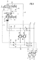
- the power control device in the embodiment shown in Fig. 1, the power control device according to the invention generally designated by the reference numeral 1.
- the power control device 1 is used to control two adjustable hydraulic pumps 2 and 3. Zur Adjustment of the delivery volume, each hydraulic pump 2, 3, an adjusting device 4th or 5 on.
- the hydraulic pumps 2, 3 each convey into separate working lines 6 and 7.
- the working lines 6 and 7 are via a shuttle valve 8 and a connecting line. 9 connected to a control pressure valve 10.
- the control pressure valve 10 is shown in the Embodiment designed as a 3/2-way valve and a control line 11 with the Adjustment 4 and 5 of the two hydraulic pumps 2 and 3 connected.
- In the in Fig. 1 illustrated basic position is the connecting line 9 via the control pressure valve 10th with a pressurized fluid tank 12 in connection.
- a pivot lever 13 of a Hyperbelreglers 16 is L-shaped in the embodiment and rotatable about an axis 14 stored. The pivot lever 13 acts via a plunger 15 on the control pressure valve 10th one. With increasing pivoting of the pivot lever 13 in the embodiment in the Clockwise, the control pressure line 11 is increasingly connected to the connecting line.
- the Swing lever 13 For pivoting the Swing lever 13 is an attack element 17, which is parallel to the arm 18 of the Swing lever 13 is displaceable, as indicated by the arrow 19. According to the schematic illustration in FIG. 1, the engagement element 17 can be move by means of a wheel 20 on the arm 18 of the pivot lever 13 rolling.
- a first Control element 21 which is connected to the control pressure line 11 and with the in the Control pressure line 11 prevailing control pressure is applied.
- the first control element 21 moves the engagement element 17 against a, preferably adjustable return spring
- the lever arm is fixed, with which the Attacking element 17 on the pivotable about the pivot axis 14 pivot lever 13th attacks.
- adjustable return spring 23 serves a second Control element 24, which via connecting lines 25 and 26 with the working lines 6 and 7 is connected.
- second actuator 24 and the working lines 6 and 7 it is also possible between the second actuator 24 and the working lines 6 and 7 to arrange a diaphragm seal, which from the in the working lines 6 and 7 prevailing working pressures generated an average working pressure. in the in Fig. 2 illustrated embodiment, however, if necessary affects the relationship of the Measuring surfaces weighted sum of the prevailing in the working lines 6 and 7 Working pressures on the attack element 17 a.
- an electromagnet 27 may be provided to those of the Power control device 1 according to the invention limited maximum power output of Influence hydraulic pumps 2 and 3 in response to an electrical control signal to be able to.
- the function of the power control device 1 according to the invention is the following:
- the adjusting devices pivot 4 and 5 e.g. due to suitable springs hydraulic pumps 2 and 3 on maximum delivery volume.
- the hydraulic pumps 2 and 3 then promote them associated working lines 6 and 7 and to the second actuator 24 is a Pressure on which pushes the engagement element 17 in Fig. 1 upwards and according to the Swivel lever 13 pivoted clockwise against the return spring 23.
- Fig. 1 Branched in accordance with a development of the invention shown in Fig. 1 the control line 11 at a branch point 28 in two control pressure branch lines 29 and 30, each leading to one of the adjusting devices 4 and 5.
- a check valve 31 and 32 are provided to Decoupling of the two control pressure branch lines 29 and 30 is in each control pressure branch line 29 and 30, a check valve 31 and 32 are provided.
- the control pressure branch lines 29 and 30 are via throttles 33 and 34 with the pressure fluid tank 12th connected.
- a pressure relief valve 35 or 36 arranged between the working lines 6 and 7 or between the connecting lines 25 and 26 and the control pressure branch lines 30 and 29 is corresponding to According to the invention, in each case a pressure relief valve 35 or 36 arranged.
- Fig. 2 shows a second embodiment of the power control device according to the invention.
- elements with matching reference numerals provided, so that in this respect a repetitive description is unnecessary.
- the difference of the embodiment shown in FIG. 2 with respect to the basis of Fig. 1 already described embodiment consists essentially in that by the power control device 1 according to the invention in addition to the first and second Hydraulic pump 2 and 3, a third hydraulic pump 40 is driven, which in a third Working line 41 promotes.
- the third working line 41 is via another connecting line 42 connected to the second actuator 24, so that the engagement element 17 with the possibly weighted sum of those prevailing in working lines 6, 7 and 41 Working pressures is applied.
- the control line 11 branches at the Branch point 28 in a third control pressure branch line 43, of the Branching point 28 is separated by a third check valve 44.
- the third Control pressure branch line 43 leads to the adjusting device 45 of the third hydraulic pump 40.
- the third control pressure branch line 43 is connected via a throttle 46 with the Pressure fluid tank 12 connected.
- To secure the third working line 42 serves a third pressure relief valve 47, between the connecting line 42 and the Control pressure branch line 43 is arranged.
- Power control device 1 is in addition to the two hydraulic pumps 2 and 3 a further hydraulic pump 50 is provided, which promotes in a third working line 51.
- a further hydraulic pump 50 is provided, which promotes in a third working line 51.
- the second actuator 24 consists of a first adjusting chamber 52 and a second actuating chamber 53, so that on the engagement element 17 both the working pressure of the first working line 6 and the working pressure of the second Working line 7 can attack.
- the third is Hydraulic pump 50, however, not connected to the control line 11. There is no Connection between the second actuator 24 and the third working line 51.
- the third working line 51 is rather via a connecting line 54 with a third, connected directly to the pivot lever 13 attacking actuator 55.
- the third control element 55 has a pressure chamber 56 which communicates with the connecting line 54 is connected and a piston 57 acted upon against a return spring 58.
- a piston 57 acted upon against a return spring 58.
- the Piston 57 presses on a pivot 59 on the pivot lever 13. If in the third Working line 51 no or only a low working pressure is present, the effect Return spring 58 unhindered via the plunger 59 on the pivot lever 13 and the Spring forces of the return spring 23 and the return spring 58 add up. As soon as, however at the working line 51, a sufficient working pressure is present, the piston 57 in Fig. 3 moves to the right, so that the plunger 59 lifts from the pivot lever 13.
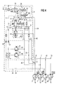
- FIG. 4 shows a fourth exemplary embodiment of the power control device according to the invention 1, where already described elements with matching reference numerals are provided.
- a third hydraulic pump 40 provided, the working line 41 via a connecting line 42 to the second Setting device 24 is connected.
- a additional pressure chamber 60 is provided at the second adjusting device 24 .
- the attack element 17 therefore affects the possibly weighted sum of the working pressures in the three working lines 6, 7 and 41.
- the third hydraulic pump 40 in the embodiment shown in FIG. 4 not as Variable, but designed as a constant pump and therefore not with the Control line 11 connected.
- a fourth hydraulic pump 50 is provided, the working line 51 via a Connecting line 54 is connected to the described third actuator 55 to the performance of the power device 1 for the first hydraulic pump 2 and the second hydraulic pump 3 as already described with reference to FIG. 3 to influence.
- To the working line 51 connected consumers is therefore in this embodiment a certain priority too.
- Fig. 5 shows a fifth embodiment of the power control device according to the invention 1. Again, there are already different elements with matching Provided with reference numerals.
- the difference from the embodiment shown in FIG. 4 and already described consists essentially in that the third hydraulic pump 40 is not as Constant pump but is designed as a variable displacement pump.
- Your adjusting device 45 is in a similar manner as in the embodiment shown in FIG. 2 via a Control pressure branch line 42 is connected to the control pressure line 11 and is controlled by the Power control device 1 according to the invention also regulated.
- the Power control device 1 By changing the measuring surfaces of the pressure chambers 53, 52 and 60, the Power control device 1 to hydraulic pumps with different nominal pressures or Sizes are adjusted, in which case the individual working pressures on the assigned Measuring surfaces are weighted. Due to the hyperbola performance is a good one Power utilization of the individual hydraulic pumps possible.
- the inventive Power control device 1 can be used for a wide variety of pump types, pump combinations and pump sizes are used. The multiple use of the invention Power control device 1 for different pump types and pump combinations increases the number of units and reduces the number of controller variants, resulting in a Cost reduction contributes. Interventions or a change in the performance characteristics are possible without great effort.
- the adjustment work on the individual hydraulic pumps 2, 3, 40, 50 is considerably simplified.
- the power control device 1 according to the invention can independent of the adjusting devices 4, 5, 45 of the hydraulic pumps 2, 3 and 40 be set. A subsequent change in performance is through simple exchange the power control device 1 readily possible.
Landscapes
- Engineering & Computer Science (AREA)
- Mechanical Engineering (AREA)
- General Engineering & Computer Science (AREA)
- Fluid-Pressure Circuits (AREA)
- Control Of Positive-Displacement Pumps (AREA)
- Operation Control Of Excavators (AREA)
Description
- Fig. 1
- ein erstes Ausführungsbeispiel der erfindungsgemäßen Leistungsregeleinrichtung,
- Fig. 2
- ein zweites Ausführungsbeispiel der erfindungsgemäßen Leistungsregeleinrichtung,
- Fig. 3
- ein drittes Ausführungsbeispiel der erfindungsgemäßen Leistungsregeleinrichtung,
- Fig. 4
- ein viertes Ausführungsbeispiel der erfindungsgemäßen Leistungsregeleinrichtung, und
- Fig. 5
- ein fünftes Ausführungsbeispiel der erfindungsgemäßen Leistungsregeleinrichtung.
Claims (11)
- Leistungsregeleinrichtung (1) zum Begrenzen der Leistung zumindest einer ersten und einer zweiten an der Leistungsregeleinrichtung (1) angeschlossenen, mittels zumindest einer Verstellvorrichtung (4, 5) verstellbaren und in jeweils eine Arbeitsleitung (6, 7) fördernden Hydropumpe (2, 3)
mit einem Hyperbelregler (16), der über einen Schwenkhebel (13) auf ein Steuerdruckventil (10) zurückwirkt und einem Angriffselement (17), das auf dem Schwenkhebel (13) so verschiebbar ist, daß der Hebelarm, mit welchem das Angriffselement (17) an dem Schwenkhebel (13) angreift, veränderbar ist, wobei das Angriffselement (17) mit den in den Arbeitsleitungen (6, 7) herrschenden Arbeitsdrücken beaufschlagt ist,
dadurch gekennzeichnet, daß für die erste und zweite Hydropumpe (2, 3) jeweils eine separate Verstellvorrichtung (4, 5) vorgesehen ist und die Leistungsregeleinrichtung (1) als von den Verstellvorrichtungen (4, 5) baulich getrennte Ventileinheit ausgebildet ist, und
daß durch das Steuerdruckventil (10) ein Steuerdruck geregelt wird, der der Verstellvorrichtung (4, 5) sowohl der ersten als auch der zweiten Hydropumpe (2, 3) zum Verstellen des Fördervolumens über eine Steuerdruckleitung (11) zugeführt wird, und der Hebelarm, mit welchem das Angriffselement (17) an dem Schwenkhebel (13) angreift, durch ein erstes Stellelement (21) festgelegt ist, das mit der Steuerdruckleitung (11) verbunden ist. - Leistungsregeleinrichtung nach Anspruch 1,
dadurch gekennzeichnet, daß die erste Hydropumpe (2) in eine erste Arbeitsleitung (6) und die zweite Hydropumpe (3) in eine zweit Arbeitsleitung (7) fördert und
daß ein zweites Stellelement (24) sowohl mit der ersten als auch mit der zweiten Arbeitsleitung (6, 7) verbunden ist und das Angriffselement (17) und den Schwenkhebel (13) gegen eine erste Rückstellfeder (23) beaufschlagt. - Leistungsregeleinrichtung nach Anspruch 1 oder 2,
dadurch gekennzeichnet, daß das erste Stellelement (21) das Angriffselement (17) gegen eine zweite Rückstellfeder (22) verschiebt, wobei das Angriffselement (17) an dem Schwenkhebel (13) mit einem Hebelarm angreift, der umgekehrt proportional zu dem Steuerdruck ist. - Leistungsregeleinrichtung nach einem der Ansprüche 1 bis 3,
dadurch gekennzeichnet, daß das Steuerdruckventil (10) über ein Wechselventil (8) so mit den Arbeitsleitungen (6, 7) der ersten und zweiten Hydropumpen (2, 3) verbunden ist, daß dem Steuerdruckventil (10) jeweils der höchste Arbeitsdruck der ersten und zweiten Hydropumpe (2, 3) zugeführt wird. - Leistungsregeleinrichtung nach Anspruch 4,
dadurch gekennzeichnet, daß das Steuerdruckventil (10) ein 3/2-Wegeventil ist, dessen erster Anschluß mit dem Wechselventil (8), dessen zweiter Anschluß mit einem Druckfluid-Tank (12) und dessen dritter Anschluß mit der Steuerleitung (11) verbunden ist, wobei das Steuerdruckventil (10) so mit dem Schwenkhebel (13) verbunden ist, daß mit zunehmender Beaufschlagung des Schwenkhebels (13) durch das Angriffselement (17) der Steuerdruck in der Steuerleitung (11) zunehmend erhöht wird. - Leistungsregeleinrichtung nach einem der Ansprüche 1 bis 5,
dadurch gekennzeichnet, daß das Steuerdruckventil (10) mit einem Elektromagneten (27) zusätzlich beaufschlagbar ist. - Leistungsregeleinrichtung nach einem der Ansprüche 1 bis 6,
dadurch gekennzeichnet, daß zumindest eine weitere Hydropumpe (40) vorgesehen ist, deren Arbeitsleitung (41) mit dem zweiten Stellelement (24) zusätzlich verbunden ist. - Leistungsregeleinrichtung nach Anspruch 7,
dadurch gekennzeichnet, daß die weitere Hydropumpe (40) verstellbar ist und der von dem Steuerdruckventil (10) geregelte Steuerdruck über die Steuerdruckleitung (11) einer Verstellvorrichtung (45) der weiteren Hydropumpe (40) zugeführt wird. - Leistungsregeleinrichtung nach einem der Ansprüche 1 bis 8,
dadurch gekennzeichnet, daß sich die Steuerleitung (11) in Steuerdruck-Zweigleitungen (29, 30, 43) verzweigt, die zu den Verstellvorrichtungen (4, 5, 45) der verstellbaren Hydropumpen (2, 3, 40) führen und die jeweils ein Rückschlagventil (31, 32, 44) aufweisen. - Leistungsregeleinrichtung nach Anspruch 9,
dadurch gekennzeichnet, daß jede Arbeitsleitung (6, 7, 41) über jeweils ein Druckbegrenzungsventil (35, 36, 47) mit der zu der Verstellvorrichtung (4, 5, 45) der zugeordneten Hydropumpe (2, 3, 40) führenden Steuerdruck-Zweigleitung (29, 30, 43) stromabwärts der Rückschlagventile (31, 32, 44) verbunden ist. - Leistungsregeleinrichtung nach einem der Ansprüche 1 bis 10,
dadurch gekennzeichnet, daß zumindest eine weitere Hydropumpe (50) vorgesehen ist, deren Arbeitsleitung (51) mit einem unmittelbar auf den Schwenkhebel (13) einwirkenden dritten Stellelement (55) verbunden ist.
Applications Claiming Priority (2)
| Application Number | Priority Date | Filing Date | Title |
|---|---|---|---|
| DE19808127 | 1998-02-26 | ||
| DE19808127A DE19808127C2 (de) | 1998-02-26 | 1998-02-26 | Leistungsregeleinrichtung |
Publications (3)
| Publication Number | Publication Date |
|---|---|
| EP0939225A2 EP0939225A2 (de) | 1999-09-01 |
| EP0939225A3 EP0939225A3 (de) | 2000-06-14 |
| EP0939225B1 true EP0939225B1 (de) | 2005-04-27 |
Family
ID=7858994
Family Applications (1)
| Application Number | Title | Priority Date | Filing Date |
|---|---|---|---|
| EP99103324A Expired - Lifetime EP0939225B1 (de) | 1998-02-26 | 1999-02-19 | Leistungsregeleinrichtung für mehrere verstellbare Hydropumpen |
Country Status (2)
| Country | Link |
|---|---|
| EP (1) | EP0939225B1 (de) |
| DE (2) | DE19808127C2 (de) |
Families Citing this family (3)
| Publication number | Priority date | Publication date | Assignee | Title |
|---|---|---|---|---|
| DE10151401A1 (de) * | 2001-10-18 | 2003-05-08 | Brueninghaus Hydromatik Gmbh | Summenleistungsregler und Druckmittler |
| EP3045723B1 (de) * | 2015-01-16 | 2019-04-10 | HAWE Hydraulik SE | Axialkolbenpumpe |
| CN111779649B (zh) * | 2020-06-30 | 2022-10-28 | 潍柴动力股份有限公司 | 一种变功率控制装置及液压系统 |
Family Cites Families (9)
| Publication number | Priority date | Publication date | Assignee | Title |
|---|---|---|---|---|
| DE1453518A1 (de) * | 1964-09-30 | 1969-03-27 | Linde Ag | Steuerorgan fuer die Steuerung von mehreren hydrostatischen Einheiten |
| DE1922145A1 (de) * | 1969-04-25 | 1970-10-29 | Bellows Valvair Kaemper Gmbh | Kombinationsregler |
| DE3217360A1 (de) * | 1982-05-08 | 1983-11-10 | Robert Bosch Gmbh, 7000 Stuttgart | Regeleinrichtung fuer eine verstellbare pumpe |
| DE3323278C2 (de) * | 1983-06-28 | 1986-05-22 | Hydromatik GmbH, 7915 Elchingen | Regelvorrichtung für mehrere aus hydrostatischen Getrieben bestehende Antriebsaggregate |
| JP2505457B2 (ja) * | 1987-05-01 | 1996-06-12 | カヤバ工業株式会社 | ピストンポンプの馬力制御装置 |
| JP2579194B2 (ja) * | 1988-08-01 | 1997-02-05 | 株式会社小松製作所 | 可変吐出量ポンプの制御装置 |
| DE4208925C1 (de) | 1992-03-19 | 1993-06-03 | Hydromatik Gmbh, 7915 Elchingen, De | |
| DE19626793C1 (de) * | 1996-07-03 | 1997-06-26 | Brueninghaus Hydromatik Gmbh | Hydraulische Regeleinrichtung zum parallelen Regeln mehrerer hydrostatischer Verstellpumpen |
| DE19756600C1 (de) * | 1997-12-18 | 1999-08-26 | Brueninghaus Hydromatik Gmbh | Leistungsregelventil |
-
1998
- 1998-02-26 DE DE19808127A patent/DE19808127C2/de not_active Expired - Fee Related
-
1999
- 1999-02-19 EP EP99103324A patent/EP0939225B1/de not_active Expired - Lifetime
- 1999-02-19 DE DE59911964T patent/DE59911964D1/de not_active Expired - Fee Related
Also Published As
| Publication number | Publication date |
|---|---|
| EP0939225A3 (de) | 2000-06-14 |
| DE19808127A1 (de) | 1999-09-09 |
| DE19808127C2 (de) | 1999-12-09 |
| EP0939225A2 (de) | 1999-09-01 |
| DE59911964D1 (de) | 2005-06-02 |
Similar Documents
| Publication | Publication Date | Title |
|---|---|---|
| DE3535771C2 (de) | ||
| EP0149787B2 (de) | Fördermengen-Regeleinrichtung für eine verstellbare Hydropumpe | |
| EP1989450B1 (de) | Hydraulische steueranordnung | |
| DE3321484A1 (de) | Hydraulische anlage mit zwei verbrauchern hydraulischer energie | |
| DE3709504C2 (de) | Ventileinrichtung | |
| DE3422165A1 (de) | Hydraulische einrichtung mit einer pumpe und mindestens zwei von dieser beaufschlagten verbrauchern hydraulischer energie | |
| DE3420674C2 (de) | Druckversorgungseinrichtung für ein Hydrauliksystem | |
| EP0284831A2 (de) | Hydraulische Steuervorrichtung für Verbrauchergruppen | |
| EP3398418A1 (de) | Hydrauliksystem einer land- oder bauwirtschaftlich nutzbaren arbeitsmaschine | |
| EP1502027B1 (de) | Regeleinrichtung mit grenzwertregelventil | |
| EP0561153B1 (de) | Vorrichtung zur Leistungregelung von wenigstens zwei hydrostatischen Verstellpumpen | |
| EP0471166B1 (de) | Regelvorrichtung zur Regelung der Fördervolumeneinstellung mehrerer hydrostatischer Pumpen | |
| DE19626793C1 (de) | Hydraulische Regeleinrichtung zum parallelen Regeln mehrerer hydrostatischer Verstellpumpen | |
| DE19808127C2 (de) | Leistungsregeleinrichtung | |
| DE112004002768B4 (de) | Hydraulisches Steuersystem | |
| DE3422164C2 (de) | Hydraulische Anlage mit mindestens zwei Verbrauchern hydraulischer Energie | |
| DE4210252C1 (de) | ||
| DE3413913A1 (de) | Verstelleinrichtung fuer das verdraengungsvolumen einer verdraengermaschine | |
| EP0746690B1 (de) | Regeleinrichtung für eine hydropumpe | |
| DE2205508C2 (de) | Hydraulische Steuereinrichtung | |
| DE19756600C1 (de) | Leistungsregelventil | |
| EP1481167B1 (de) | Ventilanordnung | |
| DE4435750C1 (de) | Steuervorrichtung für eine hydrostatische Maschine | |
| DE10033740B4 (de) | Leistungsregeleinrichtung für beidseitige Schwenkrichtung | |
| EP0284989B1 (de) | Regeleinrichtung für wenigstens zwei mit einer gemeinsamen Arbeitsdruckleitung in Verbindung stehende hydrostatische Maschinen |
Legal Events
| Date | Code | Title | Description |
|---|---|---|---|
| PUAI | Public reference made under article 153(3) epc to a published international application that has entered the european phase |
Free format text: ORIGINAL CODE: 0009012 |
|
| AK | Designated contracting states |
Kind code of ref document: A2 Designated state(s): DE FR GB IT SE |
|
| AX | Request for extension of the european patent |
Free format text: AL;LT;LV;MK;RO;SI |
|
| PUAL | Search report despatched |
Free format text: ORIGINAL CODE: 0009013 |
|
| AK | Designated contracting states |
Kind code of ref document: A3 Designated state(s): AT BE CH CY DE DK ES FI FR GB GR IE IT LI LU MC NL PT SE |
|
| AX | Request for extension of the european patent |
Free format text: AL;LT;LV;MK;RO;SI |
|
| 17P | Request for examination filed |
Effective date: 20000808 |
|
| AKX | Designation fees paid |
Free format text: DE FR GB IT SE |
|
| GRAP | Despatch of communication of intention to grant a patent |
Free format text: ORIGINAL CODE: EPIDOSNIGR1 |
|
| GRAS | Grant fee paid |
Free format text: ORIGINAL CODE: EPIDOSNIGR3 |
|
| GRAA | (expected) grant |
Free format text: ORIGINAL CODE: 0009210 |
|
| AK | Designated contracting states |
Kind code of ref document: B1 Designated state(s): DE FR GB IT SE |
|
| REG | Reference to a national code |
Ref country code: GB Ref legal event code: FG4D Free format text: NOT ENGLISH |
|
| GBT | Gb: translation of ep patent filed (gb section 77(6)(a)/1977) |
Effective date: 20050427 |
|
| REF | Corresponds to: |
Ref document number: 59911964 Country of ref document: DE Date of ref document: 20050602 Kind code of ref document: P |
|
| REG | Reference to a national code |
Ref country code: SE Ref legal event code: TRGR |
|
| PLBE | No opposition filed within time limit |
Free format text: ORIGINAL CODE: 0009261 |
|
| STAA | Information on the status of an ep patent application or granted ep patent |
Free format text: STATUS: NO OPPOSITION FILED WITHIN TIME LIMIT |
|
| ET | Fr: translation filed | ||
| 26N | No opposition filed |
Effective date: 20060130 |
|
| PGFP | Annual fee paid to national office [announced via postgrant information from national office to epo] |
Ref country code: SE Payment date: 20080214 Year of fee payment: 10 Ref country code: IT Payment date: 20080223 Year of fee payment: 10 Ref country code: GB Payment date: 20080220 Year of fee payment: 10 Ref country code: DE Payment date: 20080219 Year of fee payment: 10 |
|
| PGFP | Annual fee paid to national office [announced via postgrant information from national office to epo] |
Ref country code: FR Payment date: 20080214 Year of fee payment: 10 |
|
| EUG | Se: european patent has lapsed | ||
| GBPC | Gb: european patent ceased through non-payment of renewal fee |
Effective date: 20090219 |
|
| REG | Reference to a national code |
Ref country code: FR Ref legal event code: ST Effective date: 20091030 |
|
| PG25 | Lapsed in a contracting state [announced via postgrant information from national office to epo] |
Ref country code: DE Free format text: LAPSE BECAUSE OF NON-PAYMENT OF DUE FEES Effective date: 20090901 |
|
| PG25 | Lapsed in a contracting state [announced via postgrant information from national office to epo] |
Ref country code: GB Free format text: LAPSE BECAUSE OF NON-PAYMENT OF DUE FEES Effective date: 20090219 Ref country code: FR Free format text: LAPSE BECAUSE OF NON-PAYMENT OF DUE FEES Effective date: 20090302 |
|
| PG25 | Lapsed in a contracting state [announced via postgrant information from national office to epo] |
Ref country code: IT Free format text: LAPSE BECAUSE OF NON-PAYMENT OF DUE FEES Effective date: 20090219 |
|
| PG25 | Lapsed in a contracting state [announced via postgrant information from national office to epo] |
Ref country code: SE Free format text: LAPSE BECAUSE OF NON-PAYMENT OF DUE FEES Effective date: 20090220 |