EP0939167A1 - Verbundpflasterung für Böden und Ufer von Flussbetten - Google Patents
Verbundpflasterung für Böden und Ufer von Flussbetten Download PDFInfo
- Publication number
- EP0939167A1 EP0939167A1 EP99400277A EP99400277A EP0939167A1 EP 0939167 A1 EP0939167 A1 EP 0939167A1 EP 99400277 A EP99400277 A EP 99400277A EP 99400277 A EP99400277 A EP 99400277A EP 0939167 A1 EP0939167 A1 EP 0939167A1
- Authority
- EP
- European Patent Office
- Prior art keywords
- blocks
- block
- base
- paving
- symmetry
- Prior art date
- Legal status (The legal status is an assumption and is not a legal conclusion. Google has not performed a legal analysis and makes no representation as to the accuracy of the status listed.)
- Granted
Links
- 238000003825 pressing Methods 0.000 claims description 2
- 230000001788 irregular Effects 0.000 abstract description 2
- 238000000034 method Methods 0.000 description 13
- 230000004224 protection Effects 0.000 description 10
- 230000000694 effects Effects 0.000 description 7
- 239000002689 soil Substances 0.000 description 7
- XLYOFNOQVPJJNP-UHFFFAOYSA-N water Substances O XLYOFNOQVPJJNP-UHFFFAOYSA-N 0.000 description 6
- 238000006073 displacement reaction Methods 0.000 description 4
- 230000007704 transition Effects 0.000 description 4
- 230000003628 erosive effect Effects 0.000 description 3
- XEEYBQQBJWHFJM-UHFFFAOYSA-N Iron Chemical compound [Fe] XEEYBQQBJWHFJM-UHFFFAOYSA-N 0.000 description 2
- 230000000903 blocking effect Effects 0.000 description 2
- 238000010276 construction Methods 0.000 description 2
- 238000000605 extraction Methods 0.000 description 2
- 239000004746 geotextile Substances 0.000 description 2
- 238000009434 installation Methods 0.000 description 2
- 238000004519 manufacturing process Methods 0.000 description 2
- 230000005012 migration Effects 0.000 description 2
- 238000013508 migration Methods 0.000 description 2
- 238000000465 moulding Methods 0.000 description 2
- 230000002787 reinforcement Effects 0.000 description 2
- 240000008042 Zea mays Species 0.000 description 1
- 238000004873 anchoring Methods 0.000 description 1
- 239000010426 asphalt Substances 0.000 description 1
- 238000005056 compaction Methods 0.000 description 1
- 230000001419 dependent effect Effects 0.000 description 1
- 230000007613 environmental effect Effects 0.000 description 1
- 238000007667 floating Methods 0.000 description 1
- 238000003780 insertion Methods 0.000 description 1
- 230000037431 insertion Effects 0.000 description 1
- 229910052742 iron Inorganic materials 0.000 description 1
- 238000005304 joining Methods 0.000 description 1
- 238000012423 maintenance Methods 0.000 description 1
- 230000021715 photosynthesis, light harvesting Effects 0.000 description 1
- 238000002360 preparation method Methods 0.000 description 1
- 230000003014 reinforcing effect Effects 0.000 description 1
- 230000000284 resting effect Effects 0.000 description 1
- 230000000717 retained effect Effects 0.000 description 1
- 239000011435 rock Substances 0.000 description 1
- 238000004162 soil erosion Methods 0.000 description 1
- 235000013311 vegetables Nutrition 0.000 description 1
Images



Classifications
-
- E—FIXED CONSTRUCTIONS
- E02—HYDRAULIC ENGINEERING; FOUNDATIONS; SOIL SHIFTING
- E02B—HYDRAULIC ENGINEERING
- E02B3/00—Engineering works in connection with control or use of streams, rivers, coasts, or other marine sites; Sealings or joints for engineering works in general
- E02B3/04—Structures or apparatus for, or methods of, protecting banks, coasts, or harbours
- E02B3/12—Revetment of banks, dams, watercourses, or the like, e.g. the sea-floor
- E02B3/14—Preformed blocks or slabs for forming essentially continuous surfaces; Arrangements thereof
-
- E—FIXED CONSTRUCTIONS
- E02—HYDRAULIC ENGINEERING; FOUNDATIONS; SOIL SHIFTING
- E02B—HYDRAULIC ENGINEERING
- E02B3/00—Engineering works in connection with control or use of streams, rivers, coasts, or other marine sites; Sealings or joints for engineering works in general
- E02B3/04—Structures or apparatus for, or methods of, protecting banks, coasts, or harbours
- E02B3/12—Revetment of banks, dams, watercourses, or the like, e.g. the sea-floor
- E02B3/129—Polyhedrons, tetrapods or similar bodies, whether or not threaded on strings
Definitions
- the invention relates to a self-locking artificial paving for bottoms and banks river beds or torrents.
- This type of tiling is useful whenever a resistance to tearing and detachment is necessary, in particular for the protection against hydraulic erosion.
- riprap made of natural rocks.
- Such a riprap consists of blocks paired with more or less precision.
- the object of the invention is to remedy the preceding drawbacks of these known methods of hydraulic protection in free blocks, by providing paving self-locking artificial consisting of blocks with mutual jamming.
- each block can have a polygonal contour base regular (equilateral triangle, square, hexagon, etc.), or irregular polygonal (triangle isosceles, rectangle, etc %), or curve (circle, tortoiseshell, bicorne, etc ).
- each block has a shape comprising at least four faces, symmetrical two by two with respect to the same axis of symmetry.
- a first preferred form of these blocks is such that the four faces are symmetrical two by two with respect to the same axis of symmetry have a same slope with respect to this axis of symmetry.
- a second preferred block shape is such that the four faces symmetrical two by two with respect to the same axis of symmetry have a point single common located on this axis of symmetry.
- the paving blocks according to the invention are preferably made of concrete ordinary molded, with a low resistance requirement. These two forms are simple to make by molding, and are compact enough to not be no need to provide reinforcement in concrete. We have a large latitude for the quality of the concrete (dosage, aggregates, implementation ). This latitude must allow a reduced cost.
- the weight of the blocks is chosen according to the application and the conditions hydraulic to which the paving will be subject (speed, water height, ).
- the order of size of this weight can vary between a few tens of kilograms and several tonnes, depending on the use of the blocks for hydraulic protection either in rivers, either in torrents; but also in the maritime domain for the protection of structures or from the coast.
- the wedge shape of the blocks provides optimal nesting and wedging effective of the whole.
- the wedge is reinforced with each relative movement of the blocks in relation to each other: Indeed, the blocks whose base is in contact with the ground (summit at the top), rest on a large surface, and therefore exercise on the ground a low pressure constraint. Conversely, the returned blocks (base in high), rest on their point, of much smaller surface, and exercise on the ground a much stronger constraint. These blocks therefore tend to sink into the ground, and thus reinforce the jamming.
- the jamming allows, to a certain extent, a reconfiguration paving in the case of local subsidence, or differential settlement, causing relative displacement of the blocks.
- This paving retains mobility vertical relative of the blocks, which allows automatic adjustment of this displacement relative, maintaining the continuity of the paving.
- the paving according to the invention can be used to dissipate energy and slow down the flow.
- Energy dissipation results from vortices caused by the passage of water between the projecting blocks, and the roughness is related to the height of the protrusion. This height is determined by the interval left at installation between the blocks whose the base is placed at the bottom; it is therefore possible to choose the roughness of the paving, and adjust it precisely to the desired goal.
- the lateral faces 81 to 84 have an inclination ⁇ of the order of 10 to 20 degrees with respect to the axis of symmetry YY.
- face B1 is larger than the face S1, and they will be called respectively base and vertex of the block, in what follows.
- the shape is truncated at the level of the face S1.
- the report of the length over the width of the base is close to 1.5; and the height of the block is close to the width of the base. It can be used to make smooth paving or paving rough.
- FIG. 2 represents an example of smooth paving which can be used to protect the bottom, or the bank of a river bed. It is produced by means of blocks of the type described with reference to FIG. 1.
- Blocks 1, ..., 6, are juxtaposed according to a first two-dimensional pattern. They are aligned in rows orthogonal to each other. Each row is made by placing the base of the blocks alternately at the top and bottom; and aligning the blocks sometimes along the length of the base and sometimes along the width. In the same row, the axes of symmetry of all the blocks are in the same plane. Thus, each row has a crenellated shape on two sides, in a plane parallel to the ground, and fits into the two adjacent rows. It is integral with the two adjacent rows thanks to the wedging of the blocks.
- this pattern allows an overlap total soil, as shown in Figure 2. Otherwise, there remains a small empty space in the center of each pattern made up of four blocks. These spaces allow drainage which avoids possible under-pressure under the paving. Through however, they are too small to allow soil erosion. The grain size of the soil is therefore unimportant, it is not necessary to provide an undercoat of transition or a geotextile, except in the very specific case of powdery soil.
- FIG. 3 represents an elevation view, along the axis AA, of this example of paving.
- Block 2 is inserted as a corner between blocks 1 and 3.
- Block 4 is inserted as a corner between blocks 3 and 5.
- the truncated vertices S1, S3, S5, respectively of blocks 1, 3, 5, and the bases B2, B4, ... respectively blocks 2, 4, ..., appear on the visible side of the paving.
- the bases B1, B3, B5, ..., respectively of blocks 1, 3, 5, and the vertices S2, S3, ..., respectively of blocks 2, 3, ...., are on the not visible side of the paving. All the faces of all the blocks having, by construction the same slope a, and the ground being supposed plane, all the faces in contact are theoretically contiguous on all their surface. The friction is therefore uniformly distributed and ensures perfectly regular wedging.
- the process for constructing this paving is as follows.
- the blocks whose base is at the bottom, such as blocks 1, 3, 5, are laid on the ground, first, at a same altitude, after a leveling of the ground. They are placed on the ground leaving between them intervals all having the same width, such that it is possible to insert blocks 2, 4, ... in the spaces left by the previously arranged blocks, in allowing them to descend to the ground. This width lets them go down to ground but leaves no play when they come into contact with the ground, so that the blocks get stuck.
- block 2 is inserted between the blocks 1 and 3, which belong to the row along the line AA, and between two blocks (including block 6) which belong to a row perpendicular to the line AA.
- the intervals are equal in all rows and are chosen such that this wedging is obtained when the truncated vertices S2, S4, ..., touch the ground. Therefore, the apparent side of the paving is smooth, if we consider as negligible the imperfections in molding and laying of blocks, and in soil preparation.
- the faces of the pyramid have an inclination of the order of 10 to 20 degrees per relative to the axis of symmetry XX.
- face B11 is larger than the face S11, and they will be called respectively base and vertex of the block, in what follows.
- the shape is truncated at the face S11 of the block.
- the ratio of the length to the width of the base is close to 1.5; and the block height is close to the width of the base.
- This second embodiment differs from first by the fact that the lateral faces 7, 9 do not have the same slope as the faces 8, 10. It can be used for smooth paving or rough paving.
- Figure 5 shows in perspective a rough paving made with the type of block shown in Figure 4. It shows only two parallel rows of this paving: a row consisting of blocks 11, 12, 13, 14, 15; and a row parallel to the previous one consisting of blocks 16, 17, 18.
- the blocks are juxtaposed according to the first pattern, as in the embodiment shown in Figure 1, as regards the arrangement in the plane of the paving. They are therefore aligned in rows orthogonal to each other.
- Each row is made by placing the base of the blocks alternately at the top and bottom; and aligning the blocks sometimes along the length of the base and sometimes along the width.
- the axes of symmetry of all the blocks are in the same plane.
- each row has a crenellated shape on two sides, in a plane parallel to the ground, and fits into the two adjacent rows. It is integral with the two adjacent rows thanks to the wedging of the blocks.
- FIG. 6 represents a plan view of the example of paving shown in perspective in FIG. 5. It shows in particular an axis BB which passes through the axis of symmetry of the blocks 11, 12, 13, 14,15.
- FIG. 7 represents an elevation view, along the axis BB, of the example of paving shown in FIG. 5.
- the vertices S12, S14, S16 belonging respectively to blocks 12, 14, 16, are located at the top , ie on the visible side of the paving.
- the blocks 13 and 15, on the other hand, are turned over, that is to say that the bases B13, B15 of these blocks are located at the top, that is to say on the apparent side of the paving.
- the particularity of this exemplary embodiment resides in the fact that the blocks 12, 14, 16, 18 are arranged projecting with respect to the blocks 13, 15, 17. This arrangement is obtained by arranging the blocks 12, 14, 16, 18 , ... on the ground, leaving gaps between them all having the same width such that it is possible to insert the blocks 13, 15, 17, ... in the spaces left by the previously arranged blocks, by allowing to descend to a predetermined height corresponding to the desired height for the projection, without being able to go beyond.
- the choice of the width of the intervals determines the height of the
- FIG. 7 illustrates the energy dissipative effect of the roughness of this example of paving. It shows the vortices created in the water by the truncated vertices S12, S14 which are projecting from the bases B11, B13, and B15 of blocks 11, 13, and 15 respectively. On the other hand, it shows that the bases B12, B14, ..., of blocks 12, 14, ... are placed on the ground, after a leveling of the ground, while the vertices truncated S13, S15, ... blocks 13,15, ... are driven into the ground (by threshing, and possibly by prior digging of the soil at their location).
- Such paving dissipative is particularly useful for increasing the roughness of the bottom of a torrent so decrease the speed of the current.
- Figure 7 shows that two neighboring blocks are in contact by a surface less than the surface of a face, because the contacting faces do not have the same slope in the second embodiment of the block (figure 4).
- FIG. 8 represents a rough paving similar to that of FIG. 7 but produced with the first embodiment of the block (FIG. 1).
- the blocks homologous to those in FIG. 7 have the same reference but with the attribute '. All the faces in contact are in contact over a larger area than in the previous example, because all the faces have the same slope, by construction.
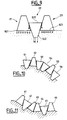
- FIG. 9 illustrates the blocking effect of the blocks according to the invention, and the automatic catching effect of the relative movement of a block. It shows, in elevation, three blocks 21, 22, 23, which are for example of the type shown in FIG. 4.
- the blocks 21 and 23 rest respectively on the ground by their bases B21, 823; while the block 22 rests on the one hand on its top S22 which is sunk into the ground, and on the other hand rubs on the blocks 21 and 23 by a part of the periphery of its base B22.
- the weight of the block 22 exerts a pressure on the ground, on the reduced surface of the truncated top S22, which is greater than the pressure exerted by the weight of the blocks 21 and 23 on the ground situated respectively under the bases B22 and 823.
- the block 22 is therefore more likely than blocks 21 and 23 to sink into the ground.
- This phenomenon of relative displacement tends to increase the jamming of the block 22 between the blocks 21 and 23, which jamming prevents the blocks 21 and 23 from lifting from the ground, from tilting, and from being carried away by the stream of water.
- This assembly allows, to a certain extent, a reconfiguration of the paving in the case of local compaction of the soil, causing a relative displacement of the blocks. Indeed, this assembly retains the relative vertical mobility of the blocks, which allows the wedging and the maintenance of the wedging by an automatic catching up of the gaps created by the subsidence of the ground or the descent of the blocks which sink into the ground.
- leaky trapezoidal section of the projecting blocks limits the risk of entanglement of floating bodies, and facilitates their detachment when the level goes up.
- the paving method according to the invention is intended for flat ground, but it can be suitable for slope breaks, for example for the transition between bottom and bank.
- FIG. 10 represents an elevation view of a rough pavement produced on a convex-shaped floor.
- the blocks 51 to 56 are of the type shown in FIG. 4. They have the shape of a truncated pyramid with a rectangular base and are arranged along a curved line. It is therefore not possible to alternate regularly a block having its base at the top then a block having its base at the bottom. They are arranged in order 51 to 56.
- the blocks 51, 53, 54, 56 have their base at the top, while the blocks 52 and 55 have their top at the top.
- the blocks 53 and 54 are therefore two consecutive blocks which have their base placed at the top.
- Figure 11 shows an elevational view of a paving made on a concave floor.
- the blocks 61 to 66 are of the type shown in FIG. 4. They have the shape of a truncated pyramid with a rectangular base and are arranged in this order along a curved line.
- the top of the blocks 61, 63, 64, 66 is arranged at the top, and the base of the blocks 62 and 65 is arranged at the top.
- Two successive blocks, 63 and 64, have their top placed at the top so that the paving has a concave shape which follows the concave shape of the ground.
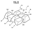
- FIG. 12 represents a perspective view of another exemplary embodiment of rough paving comprising blocks in the shape of a truncated pyramid, with rectangular base, such as that shown in FIG. 4.
- the blocks are aligned in rows orthogonal to each other. other. In the same row, the axes of symmetry of all the blocks are in the same plane. Each row is made by placing the base of the blocks alternately at the top and bottom.
- This example differs from the paving example shown in Figures 5, 6, 7, in that the blocks are juxtaposed in another two-dimensional pattern: the longitudinal axis of the base of all the blocks is in the same direction. Each lateral face of a block is therefore in contact with a homologous face of another block.
- Each row does not have a crenellated shape: it has a constant width equal to the width or the length of the base of a block, depending on the direction of the row considered. It is integral with the two adjacent rows thanks to the wedging of the blocks.
- a first row consists of blocks 32, 33, 34, 35, ...
- a second row, parallel to the first, consists of blocks 36, 37, 38, ...
- the vertices S32, S34, S36, S38, ... belonging respectively to blocks 32, 34, 36, 38, ... are located in high, ie on the visible side of the paving.
- the blocks 33, 35, 37, ... are returned, that is to say that the bases B33, B35, B37, ... of these blocks are located at the top, on the side apparent from the paving.
- the blocks 32, 34, 36, 38 are arranged projecting relative to the blocks 33, 35, 37. This arrangement is obtained by arranging blocks 32, 34, 36, 38, ...
- FIG. 13 represents an alternative embodiment of the block shown in FIG. 1 for example.
- This block 25 has a hole 26 which passes completely through it along its axis of symmetry XX.
- This hole is cylindrical and has a diameter of the order of 5 cm for example. It can be used on the one hand for handling this block, and on the other hand to secure this block to other blocks.
- the mutual jamming of the neighboring blocks ensures the resistance of the blocks to tearing off by a stream of water, however there is a problem at the edge of the paving, since the last row of blocks is not retained by another row.
- a first solution to this problem is to extend the paving to an area where hydraulic erosion becomes negligible.
- a second solution consists in reinforcing the cohesion of the paving at least on its border, thanks to pins, in concrete iron, in the shape of U.
- Figure 14 illustrates this reinforcement process.
- This figure shows by way of example two U-shaped pins, 98 and 99.
- Pins 98 and 99 are placed on the ground, in a position such that their branches are turned upwards.
- a block 30, comprising a hole 94 has been threaded on a first branch of the pin 98.
- a block 32 comprising a hole 96 has been threaded both on a branch of the pin 98 and on a branch of the pin 99.
- a block 33 comprising a hole 97, is being threaded on a second branch of pin 99.
- a block 31 has been inserted between blocks 30 and 32, so as to remain wedged between the blocks 30 and 32.
- FIG. 14 also illustrates a method of handling blocks of the type of that shown in FIG. 13.
- This handling method consists in using a special pliers comprising two opposite levers 41 and 43. These two levers have respectively two spouts 47 and 48 which are capable of opening.
- the two spouts 47 and 48 are each articulated with respect to a connecting piece 42.
- the levers 41, 43 and the connecting piece 42 are connected to three cables 44, 46, 45, respectively. These three cables are suspended from a crane.
- the two nozzles 47 and 48 are closed then introduced into the hole of the block, for example hole 97 of block 33. Then they are slightly open until it hits the wall of hole 97, pulling on levers 41 and 43 by two cables 44 and 46.
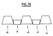
- FIG. 15 represents an elevation view of an exemplary embodiment of paving, comprising two different types of block according to the invention.
- the blocks all have the same shape, pyramid for example, and the same basic dimensions, but do not have the same height.
- the blocks 40, 42, 44, 46, ... whose base is placed at the bottom have a double height, for example, the height of the blocks 41, 43, ... whose base is placed at the top.
- the paving is carried out according to the first pattern described with reference to FIGS. 5, 6, 7. It is thus possible to obtain a roughness of the paving without pressing the blocks 41, 43, ... more than the blocks 40, 42, 44, 46, ...; or, if the blocks are pressed in, it is possible to increase the roughness obtained by a given insertion difference.
- FIG. 16 represents two blocks 71, 72 having a regular pyramidal shape the base of which is an isosceles triangle.
- FIG. 17 represents two blocks 73, 74 having a regular pyramidal shape the base of which is a square.
- FIG. 18 represents two blocks 78, 79 having a conical shape with a circular base.
- FIG. 19 represents an elevation view of a paving made up of blocks such as those represented in FIG. 18. It shows the hexagonal shape of the pattern made up of six blocks, three whose base is at the bottom and three whose base is at high.
- This paving comprises an empty space 77, of non-negligible volume, at the center of each pattern.
- This vacuum 77 can contribute to the dissipative effect of the paving, but it can also be a drawback in the case where the ground is powdery and can therefore be carried away by the current flowing between the blocks through the empty spaces 77.
- the exemplary embodiments shown in the figures 16 to 19 have a shape that is not truncated, where at least that is sharper than the exemplary embodiments illustrated by FIGS. 1 and 4.
- the blocks of more form have the advantage of being able to be driven into the ground more easily to improve the anchoring of the blocks whose base is placed at the top, and therefore the resistance of the whole paving.
Landscapes
- General Engineering & Computer Science (AREA)
- Engineering & Computer Science (AREA)
- Structural Engineering (AREA)
- Ocean & Marine Engineering (AREA)
- Mechanical Engineering (AREA)
- Civil Engineering (AREA)
- Environmental & Geological Engineering (AREA)
- Chemical & Material Sciences (AREA)
- Crystallography & Structural Chemistry (AREA)
- Inorganic Chemistry (AREA)
- Revetment (AREA)
- Road Paving Structures (AREA)
- Artificial Fish Reefs (AREA)
- Road Paving Machines (AREA)
- Finger-Pressure Massage (AREA)
Applications Claiming Priority (2)
| Application Number | Priority Date | Filing Date | Title |
|---|---|---|---|
| FR9802320 | 1998-02-26 | ||
| FR9802320A FR2775304B1 (fr) | 1998-02-26 | 1998-02-26 | Bloc a coincement mutuel et procede pour la realisation d'un pavage artificiel auto-bloquant |
Publications (2)
| Publication Number | Publication Date |
|---|---|
| EP0939167A1 true EP0939167A1 (de) | 1999-09-01 |
| EP0939167B1 EP0939167B1 (de) | 2003-09-03 |
Family
ID=9523387
Family Applications (1)
| Application Number | Title | Priority Date | Filing Date |
|---|---|---|---|
| EP99400277A Expired - Lifetime EP0939167B1 (de) | 1998-02-26 | 1999-02-08 | Verbundpflasterung für Böden und Ufer von Flussbetten |
Country Status (5)
| Country | Link |
|---|---|
| EP (1) | EP0939167B1 (de) |
| AT (1) | ATE248954T1 (de) |
| DE (1) | DE69910864T2 (de) |
| ES (1) | ES2203025T3 (de) |
| FR (1) | FR2775304B1 (de) |
Cited By (5)
| Publication number | Priority date | Publication date | Assignee | Title |
|---|---|---|---|---|
| WO2003080941A1 (en) * | 2002-03-25 | 2003-10-02 | Dov Steinberg | Molded concrete foundation element and method for its manufacture |
| RU2320808C2 (ru) * | 2006-04-03 | 2008-03-27 | ФГОУ ВПО "Новочеркасская государственная мелиоративная академия" НГМА | Крепление верхового откоса плотины |
| RU2491385C2 (ru) * | 2011-12-05 | 2013-08-27 | Общество с ограниченной ответственностью (ООО) "Научный и проектный центр "БЕРЕГОЗАЩИТА" | Гибкое бетонное покрытие для защиты берегового откоса или склона |
| RU2685189C1 (ru) * | 2018-04-13 | 2019-04-16 | Федеральное государственное бюджетное образовательное учреждение высшего образования "Национальный исследовательский Московский государственный строительный университет" (НИУ МГСУ) | Крепление верхового откоса грунтовой плотины |
| CN116791642A (zh) * | 2023-08-28 | 2023-09-22 | 生态环境部南京环境科学研究所 | 一种山谷型生活垃圾填埋场的防雨水结构 |
Families Citing this family (1)
| Publication number | Priority date | Publication date | Assignee | Title |
|---|---|---|---|---|
| CN113605312A (zh) * | 2021-07-23 | 2021-11-05 | 长江生态环保集团有限公司 | 一种用于河床生态修复的新型植草砖及施工方法 |
Citations (10)
| Publication number | Priority date | Publication date | Assignee | Title |
|---|---|---|---|---|
| NL300238A (de) * | 1900-01-01 | |||
| NL49866C (de) * | 1900-01-01 | |||
| NL92988C (de) * | 1900-01-01 | |||
| FR414437A (fr) * | 1909-12-09 | 1910-09-02 | Giovanni Villa | Muraille à sec armée de fils métalliques, pour revetement des bords et lits des fleuves et canaux |
| US2344302A (en) * | 1939-06-30 | 1944-03-14 | Leroy F Harza | Revetment and block therefor |
| FR2486567A1 (fr) * | 1980-07-08 | 1982-01-15 | Cassous Rene | Blocs artificiels complementaires en beton |
| EP0102214A2 (de) * | 1982-08-19 | 1984-03-07 | GLICKMAN, Michael Neil | Baublock |
| DE8529882U1 (de) * | 1985-10-22 | 1986-09-18 | Schleich, Markus, 8399 Neuburg | Formstein aus Beton oder als Ziegel zur Herstellung von Wänden und Mauern aller Art |
| FR2631645A1 (fr) * | 1988-05-20 | 1989-11-24 | Leost Bernard | Bloc de construction reversible a calepinages multiples integrant ou non un vide technique vertical continu |
| FR2702784A1 (fr) * | 1993-03-17 | 1994-09-23 | Fontaine Ets | Elément de construction d'un ouvrage de soutènement et mur de soutènement. |
-
1998
- 1998-02-26 FR FR9802320A patent/FR2775304B1/fr not_active Expired - Fee Related
-
1999
- 1999-02-08 DE DE69910864T patent/DE69910864T2/de not_active Expired - Fee Related
- 1999-02-08 ES ES99400277T patent/ES2203025T3/es not_active Expired - Lifetime
- 1999-02-08 EP EP99400277A patent/EP0939167B1/de not_active Expired - Lifetime
- 1999-02-08 AT AT99400277T patent/ATE248954T1/de not_active IP Right Cessation
Patent Citations (10)
| Publication number | Priority date | Publication date | Assignee | Title |
|---|---|---|---|---|
| NL300238A (de) * | 1900-01-01 | |||
| NL49866C (de) * | 1900-01-01 | |||
| NL92988C (de) * | 1900-01-01 | |||
| FR414437A (fr) * | 1909-12-09 | 1910-09-02 | Giovanni Villa | Muraille à sec armée de fils métalliques, pour revetement des bords et lits des fleuves et canaux |
| US2344302A (en) * | 1939-06-30 | 1944-03-14 | Leroy F Harza | Revetment and block therefor |
| FR2486567A1 (fr) * | 1980-07-08 | 1982-01-15 | Cassous Rene | Blocs artificiels complementaires en beton |
| EP0102214A2 (de) * | 1982-08-19 | 1984-03-07 | GLICKMAN, Michael Neil | Baublock |
| DE8529882U1 (de) * | 1985-10-22 | 1986-09-18 | Schleich, Markus, 8399 Neuburg | Formstein aus Beton oder als Ziegel zur Herstellung von Wänden und Mauern aller Art |
| FR2631645A1 (fr) * | 1988-05-20 | 1989-11-24 | Leost Bernard | Bloc de construction reversible a calepinages multiples integrant ou non un vide technique vertical continu |
| FR2702784A1 (fr) * | 1993-03-17 | 1994-09-23 | Fontaine Ets | Elément de construction d'un ouvrage de soutènement et mur de soutènement. |
Cited By (6)
| Publication number | Priority date | Publication date | Assignee | Title |
|---|---|---|---|---|
| WO2003080941A1 (en) * | 2002-03-25 | 2003-10-02 | Dov Steinberg | Molded concrete foundation element and method for its manufacture |
| RU2320808C2 (ru) * | 2006-04-03 | 2008-03-27 | ФГОУ ВПО "Новочеркасская государственная мелиоративная академия" НГМА | Крепление верхового откоса плотины |
| RU2491385C2 (ru) * | 2011-12-05 | 2013-08-27 | Общество с ограниченной ответственностью (ООО) "Научный и проектный центр "БЕРЕГОЗАЩИТА" | Гибкое бетонное покрытие для защиты берегового откоса или склона |
| RU2685189C1 (ru) * | 2018-04-13 | 2019-04-16 | Федеральное государственное бюджетное образовательное учреждение высшего образования "Национальный исследовательский Московский государственный строительный университет" (НИУ МГСУ) | Крепление верхового откоса грунтовой плотины |
| CN116791642A (zh) * | 2023-08-28 | 2023-09-22 | 生态环境部南京环境科学研究所 | 一种山谷型生活垃圾填埋场的防雨水结构 |
| CN116791642B (zh) * | 2023-08-28 | 2023-10-27 | 生态环境部南京环境科学研究所 | 一种山谷型生活垃圾填埋场的防雨水结构 |
Also Published As
| Publication number | Publication date |
|---|---|
| FR2775304A1 (fr) | 1999-08-27 |
| ES2203025T3 (es) | 2004-04-01 |
| FR2775304B1 (fr) | 2002-11-29 |
| DE69910864T2 (de) | 2004-07-15 |
| DE69910864D1 (de) | 2003-10-09 |
| EP0939167B1 (de) | 2003-09-03 |
| ATE248954T1 (de) | 2003-09-15 |
Similar Documents
| Publication | Publication Date | Title |
|---|---|---|
| EP0939167B1 (de) | Verbundpflasterung für Böden und Ufer von Flussbetten | |
| EP0833988B1 (de) | Leichtes aufschüttungsbauwerk | |
| WO1980001699A1 (fr) | Bloc artificiel pour structures maritimes et fluviales | |
| EP0317458A1 (de) | Verfahren und Einrichtung zur Einstellung eines Fundamentes durch Bildung einer aus dem Boden selbst bestehenden Vermassung | |
| EP2317013B1 (de) | Drahtschotterkasten und Anordnung, die aus mindestens zwei Drahtschotterkästen besteht | |
| EP3417111B1 (de) | Verwendung eines unterlagenelements für einen steinschüttungswellenbrecher sowie zugehöriges verfahren zur herstellung eines steinschüttungswellenbrechers | |
| EP2317014A1 (de) | Kombination für die Herstellung eines Bauwerks und Gabione für diese Kombination | |
| WO2021260336A1 (fr) | Structure d'absorption d'une énergie d'impact | |
| FR3082535A1 (fr) | Systeme de protection de berge | |
| EP3983613B1 (de) | Struktur mit einer anordnung von blöcken | |
| EP0672856A1 (de) | Vorgefertigtes Joch zum Stabilisieren einer Rohrleitung, Verfahren zur Stabilisierung und ihre Anwendung | |
| FR2562922A1 (fr) | Dalle de chaussee, notamment pour des voies de circulation provisoires | |
| FR2655074A1 (fr) | Element de construction pour la constitution d'un ouvrage de soutenement, procede pour sa mise en óoeuvre et ouvrage de soutenement obtenu. | |
| FR2677052A1 (fr) | Brise-lames. | |
| FR2845702A1 (fr) | Dispositif allege et souple pour la retention de solides instables, notamment de blocs rocheux susceptibles de se detacher | |
| FR2476713A1 (fr) | Amortisseur-stabilisateur hydraulique | |
| FR2530699A1 (fr) | Structure de support, notamment pour travaux de construction sous l'eau, et procede de construction d'une telle structure | |
| FR3021981A1 (fr) | Dispositif de liaison pour relier des structures prefabriquees | |
| FR3155010A1 (fr) | Pavé en béton | |
| FR3095454A1 (fr) | Kit pour la réalisation d’un pont | |
| EP2964838A2 (de) | Filterungsvorrichtung für eine temporäre sanitäre einrichtung auf einer baustelle und behälter sowie temporäres sanitäres verfahren | |
| CH324406A (fr) | Ouvrage destiné à assurer l'immobilisation de matériaux solides de cohésion limitée | |
| FR2813620A1 (fr) | Murs de soutenement ou merlons realises a partir d'elements prefabriques et superposes | |
| FR3002558A1 (fr) | Gabion avec rangees porteuses differentes | |
| WO2007104838A1 (fr) | Ouvrage de passage couvert |
Legal Events
| Date | Code | Title | Description |
|---|---|---|---|
| PUAI | Public reference made under article 153(3) epc to a published international application that has entered the european phase |
Free format text: ORIGINAL CODE: 0009012 |
|
| AK | Designated contracting states |
Kind code of ref document: A1 Designated state(s): AT CH DE ES FR IT LI |
|
| AX | Request for extension of the european patent |
Free format text: AL;LT;LV;MK;RO;SI |
|
| 17P | Request for examination filed |
Effective date: 20000301 |
|
| AKX | Designation fees paid |
Free format text: AT CH DE ES FR IT LI |
|
| GRAH | Despatch of communication of intention to grant a patent |
Free format text: ORIGINAL CODE: EPIDOS IGRA |
|
| GRAH | Despatch of communication of intention to grant a patent |
Free format text: ORIGINAL CODE: EPIDOS IGRA |
|
| GRAA | (expected) grant |
Free format text: ORIGINAL CODE: 0009210 |
|
| AK | Designated contracting states |
Kind code of ref document: B1 Designated state(s): AT CH DE ES FR IT LI |
|
| REG | Reference to a national code |
Ref country code: CH Ref legal event code: EP |
|
| REG | Reference to a national code |
Ref country code: CH Ref legal event code: NV Representative=s name: ALTHOFF PATENTANWALTSBUERO |
|
| REF | Corresponds to: |
Ref document number: 69910864 Country of ref document: DE Date of ref document: 20031009 Kind code of ref document: P |
|
| REG | Reference to a national code |
Ref country code: ES Ref legal event code: FG2A Ref document number: 2203025 Country of ref document: ES Kind code of ref document: T3 |
|
| PLBE | No opposition filed within time limit |
Free format text: ORIGINAL CODE: 0009261 |
|
| STAA | Information on the status of an ep patent application or granted ep patent |
Free format text: STATUS: NO OPPOSITION FILED WITHIN TIME LIMIT |
|
| 26N | No opposition filed |
Effective date: 20040604 |
|
| REG | Reference to a national code |
Ref country code: FR Ref legal event code: TP |
|
| PGFP | Annual fee paid to national office [announced via postgrant information from national office to epo] |
Ref country code: IT Payment date: 20060228 Year of fee payment: 8 |
|
| PGFP | Annual fee paid to national office [announced via postgrant information from national office to epo] |
Ref country code: AT Payment date: 20070213 Year of fee payment: 9 |
|
| PGFP | Annual fee paid to national office [announced via postgrant information from national office to epo] |
Ref country code: CH Payment date: 20070214 Year of fee payment: 9 |
|
| PGFP | Annual fee paid to national office [announced via postgrant information from national office to epo] |
Ref country code: DE Payment date: 20070216 Year of fee payment: 9 |
|
| PGFP | Annual fee paid to national office [announced via postgrant information from national office to epo] |
Ref country code: ES Payment date: 20070227 Year of fee payment: 9 |
|
| PGFP | Annual fee paid to national office [announced via postgrant information from national office to epo] |
Ref country code: FR Payment date: 20080221 Year of fee payment: 10 |
|
| REG | Reference to a national code |
Ref country code: CH Ref legal event code: PL |
|
| PG25 | Lapsed in a contracting state [announced via postgrant information from national office to epo] |
Ref country code: LI Free format text: LAPSE BECAUSE OF NON-PAYMENT OF DUE FEES Effective date: 20080229 Ref country code: CH Free format text: LAPSE BECAUSE OF NON-PAYMENT OF DUE FEES Effective date: 20080229 |
|
| PG25 | Lapsed in a contracting state [announced via postgrant information from national office to epo] |
Ref country code: AT Free format text: LAPSE BECAUSE OF NON-PAYMENT OF DUE FEES Effective date: 20080208 |
|
| PG25 | Lapsed in a contracting state [announced via postgrant information from national office to epo] |
Ref country code: DE Free format text: LAPSE BECAUSE OF NON-PAYMENT OF DUE FEES Effective date: 20080902 |
|
| REG | Reference to a national code |
Ref country code: ES Ref legal event code: FD2A Effective date: 20080209 |
|
| PG25 | Lapsed in a contracting state [announced via postgrant information from national office to epo] |
Ref country code: ES Free format text: LAPSE BECAUSE OF NON-PAYMENT OF DUE FEES Effective date: 20080209 |
|
| PG25 | Lapsed in a contracting state [announced via postgrant information from national office to epo] |
Ref country code: IT Free format text: LAPSE BECAUSE OF NON-PAYMENT OF DUE FEES Effective date: 20070208 |
|
| REG | Reference to a national code |
Ref country code: FR Ref legal event code: ST Effective date: 20091030 |
|
| PG25 | Lapsed in a contracting state [announced via postgrant information from national office to epo] |
Ref country code: FR Free format text: LAPSE BECAUSE OF NON-PAYMENT OF DUE FEES Effective date: 20090302 |