EP0938870A1 - Instrument zur chirurgischen Anastomose - Google Patents
Instrument zur chirurgischen Anastomose Download PDFInfo
- Publication number
- EP0938870A1 EP0938870A1 EP99301416A EP99301416A EP0938870A1 EP 0938870 A1 EP0938870 A1 EP 0938870A1 EP 99301416 A EP99301416 A EP 99301416A EP 99301416 A EP99301416 A EP 99301416A EP 0938870 A1 EP0938870 A1 EP 0938870A1
- Authority
- EP
- European Patent Office
- Prior art keywords
- surgical device
- plow
- hollow
- organs
- needle
- Prior art date
- Legal status (The legal status is an assumption and is not a legal conclusion. Google has not performed a legal analysis and makes no representation as to the accuracy of the status listed.)
- Granted
Links
- 230000003874 surgical anastomosis Effects 0.000 title 1
- 210000000056 organ Anatomy 0.000 claims abstract description 70
- 230000008878 coupling Effects 0.000 claims abstract description 6
- 238000010168 coupling process Methods 0.000 claims abstract description 6
- 238000005859 coupling reaction Methods 0.000 claims abstract description 6
- 210000004204 blood vessel Anatomy 0.000 description 50
- 230000003872 anastomosis Effects 0.000 description 32
- 238000000034 method Methods 0.000 description 27
- 210000004351 coronary vessel Anatomy 0.000 description 16
- 210000002216 heart Anatomy 0.000 description 9
- 230000017531 blood circulation Effects 0.000 description 7
- 230000002792 vascular Effects 0.000 description 7
- 210000001367 artery Anatomy 0.000 description 6
- 229910001220 stainless steel Inorganic materials 0.000 description 6
- 239000010935 stainless steel Substances 0.000 description 6
- 238000004804 winding Methods 0.000 description 6
- 210000000038 chest Anatomy 0.000 description 4
- 238000001356 surgical procedure Methods 0.000 description 4
- 210000000709 aorta Anatomy 0.000 description 3
- 208000014674 injury Diseases 0.000 description 3
- 239000000463 material Substances 0.000 description 3
- 239000004033 plastic Substances 0.000 description 3
- 229920003023 plastic Polymers 0.000 description 3
- 230000009471 action Effects 0.000 description 2
- 230000008901 benefit Effects 0.000 description 2
- 230000015572 biosynthetic process Effects 0.000 description 2
- 239000008280 blood Substances 0.000 description 2
- 210000004369 blood Anatomy 0.000 description 2
- 230000036770 blood supply Effects 0.000 description 2
- 230000000747 cardiac effect Effects 0.000 description 2
- 229910003460 diamond Inorganic materials 0.000 description 2
- 239000010432 diamond Substances 0.000 description 2
- 238000003780 insertion Methods 0.000 description 2
- 230000037431 insertion Effects 0.000 description 2
- 210000004165 myocardium Anatomy 0.000 description 2
- 230000008733 trauma Effects 0.000 description 2
- 241000270923 Hesperostipa comata Species 0.000 description 1
- 208000031481 Pathologic Constriction Diseases 0.000 description 1
- 239000004698 Polyethylene Substances 0.000 description 1
- 208000027418 Wounds and injury Diseases 0.000 description 1
- 239000000853 adhesive Substances 0.000 description 1
- 230000001070 adhesive effect Effects 0.000 description 1
- 230000003416 augmentation Effects 0.000 description 1
- 238000010009 beating Methods 0.000 description 1
- 229920000249 biocompatible polymer Polymers 0.000 description 1
- 239000011248 coating agent Substances 0.000 description 1
- 238000000576 coating method Methods 0.000 description 1
- 230000006378 damage Effects 0.000 description 1
- 238000011161 development Methods 0.000 description 1
- 230000018109 developmental process Effects 0.000 description 1
- 210000002889 endothelial cell Anatomy 0.000 description 1
- 230000003511 endothelial effect Effects 0.000 description 1
- 238000010304 firing Methods 0.000 description 1
- 230000035876 healing Effects 0.000 description 1
- 230000003993 interaction Effects 0.000 description 1
- 230000007774 longterm Effects 0.000 description 1
- 210000004072 lung Anatomy 0.000 description 1
- 230000014759 maintenance of location Effects 0.000 description 1
- 230000013011 mating Effects 0.000 description 1
- 239000002184 metal Substances 0.000 description 1
- 238000002324 minimally invasive surgery Methods 0.000 description 1
- 230000008520 organization Effects 0.000 description 1
- 230000002093 peripheral effect Effects 0.000 description 1
- -1 polyethylene Polymers 0.000 description 1
- 229920000573 polyethylene Polymers 0.000 description 1
- 230000008569 process Effects 0.000 description 1
- 210000002321 radial artery Anatomy 0.000 description 1
- 230000000717 retained effect Effects 0.000 description 1
- 239000000523 sample Substances 0.000 description 1
- 210000003752 saphenous vein Anatomy 0.000 description 1
- HBMJWWWQQXIZIP-UHFFFAOYSA-N silicon carbide Chemical compound [Si+]#[C-] HBMJWWWQQXIZIP-UHFFFAOYSA-N 0.000 description 1
- 229910010271 silicon carbide Inorganic materials 0.000 description 1
- 239000007787 solid Substances 0.000 description 1
- 230000036262 stenosis Effects 0.000 description 1
- 208000037804 stenosis Diseases 0.000 description 1
- 238000006467 substitution reaction Methods 0.000 description 1
- 229910000811 surgical stainless steel Inorganic materials 0.000 description 1
- 210000000779 thoracic wall Anatomy 0.000 description 1
- 230000000472 traumatic effect Effects 0.000 description 1
- 230000035899 viability Effects 0.000 description 1
- 230000000007 visual effect Effects 0.000 description 1
Images


Classifications
-
- A—HUMAN NECESSITIES
- A61—MEDICAL OR VETERINARY SCIENCE; HYGIENE
- A61B—DIAGNOSIS; SURGERY; IDENTIFICATION
- A61B17/00—Surgical instruments, devices or methods, e.g. tourniquets
- A61B17/11—Surgical instruments, devices or methods, e.g. tourniquets for performing anastomosis; Buttons for anastomosis
-
- A—HUMAN NECESSITIES
- A61—MEDICAL OR VETERINARY SCIENCE; HYGIENE
- A61B—DIAGNOSIS; SURGERY; IDENTIFICATION
- A61B17/00—Surgical instruments, devices or methods, e.g. tourniquets
- A61B17/04—Surgical instruments, devices or methods, e.g. tourniquets for suturing wounds; Holders or packages for needles or suture materials
- A61B17/0482—Needle or suture guides
-
- A—HUMAN NECESSITIES
- A61—MEDICAL OR VETERINARY SCIENCE; HYGIENE
- A61B—DIAGNOSIS; SURGERY; IDENTIFICATION
- A61B17/00—Surgical instruments, devices or methods, e.g. tourniquets
- A61B17/00234—Surgical instruments, devices or methods, e.g. tourniquets for minimally invasive surgery
- A61B2017/00238—Type of minimally invasive operation
- A61B2017/00243—Type of minimally invasive operation cardiac
- A61B2017/00247—Making holes in the wall of the heart, e.g. laser Myocardial revascularization
- A61B2017/00252—Making holes in the wall of the heart, e.g. laser Myocardial revascularization for by-pass connections, i.e. connections from heart chamber to blood vessel or from blood vessel to blood vessel
-
- A—HUMAN NECESSITIES
- A61—MEDICAL OR VETERINARY SCIENCE; HYGIENE
- A61B—DIAGNOSIS; SURGERY; IDENTIFICATION
- A61B17/00—Surgical instruments, devices or methods, e.g. tourniquets
- A61B17/04—Surgical instruments, devices or methods, e.g. tourniquets for suturing wounds; Holders or packages for needles or suture materials
- A61B17/06—Needles ; Sutures; Needle-suture combinations; Holders or packages for needles or suture materials
- A61B17/06066—Needles, e.g. needle tip configurations
- A61B2017/06076—Needles, e.g. needle tip configurations helically or spirally coiled
-
- A—HUMAN NECESSITIES
- A61—MEDICAL OR VETERINARY SCIENCE; HYGIENE
- A61B—DIAGNOSIS; SURGERY; IDENTIFICATION
- A61B17/00—Surgical instruments, devices or methods, e.g. tourniquets
- A61B17/08—Wound clamps or clips, i.e. not or only partly penetrating the tissue ; Devices for bringing together the edges of a wound
- A61B2017/081—Tissue approximator
-
- A—HUMAN NECESSITIES
- A61—MEDICAL OR VETERINARY SCIENCE; HYGIENE
- A61B—DIAGNOSIS; SURGERY; IDENTIFICATION
- A61B17/00—Surgical instruments, devices or methods, e.g. tourniquets
- A61B17/11—Surgical instruments, devices or methods, e.g. tourniquets for performing anastomosis; Buttons for anastomosis
- A61B2017/1107—Surgical instruments, devices or methods, e.g. tourniquets for performing anastomosis; Buttons for anastomosis for blood vessels
-
- A—HUMAN NECESSITIES
- A61—MEDICAL OR VETERINARY SCIENCE; HYGIENE
- A61B—DIAGNOSIS; SURGERY; IDENTIFICATION
- A61B17/00—Surgical instruments, devices or methods, e.g. tourniquets
- A61B17/11—Surgical instruments, devices or methods, e.g. tourniquets for performing anastomosis; Buttons for anastomosis
- A61B2017/1135—End-to-side connections, e.g. T- or Y-connections
-
- A—HUMAN NECESSITIES
- A61—MEDICAL OR VETERINARY SCIENCE; HYGIENE
- A61B—DIAGNOSIS; SURGERY; IDENTIFICATION
- A61B17/00—Surgical instruments, devices or methods, e.g. tourniquets
- A61B17/11—Surgical instruments, devices or methods, e.g. tourniquets for performing anastomosis; Buttons for anastomosis
- A61B2017/1139—Side-to-side connections, e.g. shunt or X-connections
Definitions
- Anastomosis the surgical formation of a passage between two normally distinct organs or spaces, is a critical part of many surgical procedures. This is particularly true for coronary artery bypass graft (CABG) procedures in which one or more graft vessels are joined to coronary arteries.
- the distal end of the graft vessel is typically joined to the coronary artery distal to the stenosed or blocked portion of that artery, in order to improve the blood supply to the myocardium.
- the graft vessels normally used include the saphenous vein of the leg and the radial artery of the arm. After the graft vessels are harvested, they are cut to the correct length, and then joined on their proximal ends to a blood supply vessel, usually to the aorta.
- the graft's distal end is attached to the coronary artery.
- the internal artery IMA
- the artery is temporarily clamped, severed at a location allowing enough length to be redirected towards the heart, dissected from the chest wall and arterial side branches, and then the distal end (pedicle) is attached to the lower anterior descending coronary artery (LAD) to improve or restore blood flow to the myocardium of the heart.
- the anastomosis (the suture attachment) is made only at the distal end, or pedicle, of the IMA.
- the type of vascular anastomosis used is typically referred to as an end-to-side type. That is, the open end of the graft vessel is attached to the side of the target vessel.
- end-to-side type that is, the open end of the graft vessel is attached to the side of the target vessel.
- other types of anastomosis are used as well.
- the end-to-end type of anastomosis is common for joining together larger hollow organs such as bowel, but can also be used for heart bypass procedures, especially for cases where the arterial flow is completely occluded by the stenosis in the diseased artery.
- surgeons choose to complete all the proximal anastomoses to the aorta before commencing the distal anastomoses to the coronary arteries. In contrast, others choose to complete the distal anastomoses first. Regardless of the order, when undertaking the distal anastomoses to the coronary artery, it is important that the vessel graft be held steady and adjacent the coronary artery, with a minimum of vascular trauma and a minimum of visual and surgical obstruction by instruments in the narrow operative field.
- vascular anastomosis is accomplished by hand suturing with a tiny, curved needle and very fine suture filament.
- the suturing method is very time consuming and requires several minutes per anastomosis, even for an experienced surgeon.
- the blood flow in the newly joined vessels may be poor, and the surgeon must remove the stitches and repeat the suturing procedure.
- the time accumulated for doing the suturing is very substantial, putting the patient at risk and increasing the cost of the surgical procedure.
- the preferred type of suturing method for the anastomosis of blood vessels is where the needle is passed through the wall of the first vessel (such as the coronary artery) from the inside to the outside, and then passed from the outside to the inside of the second vessel (such as the graft vessel), so that when the suture is drawn tight, the inside walls of the vessel come together, intima-to-intima. This is to insure that the vessels heal together properly with a smooth layer of endothelial cells formed on the inside of the anastomosis.
- the first vessel such as the coronary artery
- the second vessel such as the graft vessel
- a single stitch would first be done in this manner at each of the heel and toe locations of the anastomosis, and then a running stitch would be made on each half of the anastomosis between the heel and toe along the periphery of the anastomosis.
- MIDCAB Minimally Invasive Direct Coronary Artery Bypass
- Surgical staplers are widely used for the end-to-end or side-to-side anastomosis of large, hollow organs and are often easier to use than sutures.
- the two types of surgical staplers used in such procedures are the circular stapler and the linear cutting stapler. Both of these kinds of devices require that the stapling implements of the distal ends be inserted inside of the hollow organs to be joined together.
- stapling devices which are small enough to be used inside blood vessels and which are still effective are not currently available to surgeons.
- a surgical device for attaching a first hollow organ to a second hollow organ and creating a passageway therebetween.
- the present invention may be use for both the end-to-side and the side-to-side variations of anastomosis.
- the device includes a tissue clip comprising a joining member, a first prong for entering a wall of the first hollow organ and a second prong for entering a wall of the second hollow organ.
- the prongs each have proximal ends which are attached to the joining member and distal ends extending therefrom. At least one of the prongs is pivoted at its proximal end so that the vessels can be moved into an abutting relationship.
- the device further includes a cassette having a plow for incising the vessel walls to create a passageway therebetween.
- the plow also guides a pair of spiral needles with sutures attached thereto through the walls of the vessels on either side of the passageway.
- the device further includes a means for driving the spiral needles so as to attach the vessels together.
- the device includes a frame for coupling the tissue clip and the cassette together in operational engagement.
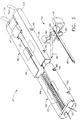
- FIG. 2 is a isometric view of the implement 20 of the surgical device 10 as the implement may be assembled prior to use.
- the cassette 60 is shown partially inserted into the frame 40.
- Right drive member 104 and left drive member 102 of the drive section 130 are attached to the proximal end of the frame 40.
- Each of these drive members transmits a torque from the control knob 182 of the handle 180 to the implement 20.
- a right surgical suture filament 161 and a left surgical suture filament 163 are shown coming out of the end cover 62 of the cassette 60.
- a tissue button 42 on the frame 40 is used to move the tissue clip 80 as will be described later.
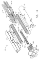
- FIG 3 shows the implement 20 of Figure 2 with the cassette 60 (also referred to as a second member) and the tissue clip 80 (also referred to as a first member) disassembled from the frame 40.
- the cassette 60 has a right cassette housing 64 and a left cassette housing 65 joined together on their distal ends by the end cover 62, and forming a longitudinal cassette opening 22.
- the cassette 60 has a generally rectangular cross section which slidably fits into the distal end of frame 40.
- the cassette contains the work ponion of the implement 20 for creating the anastomosis of the two blood vessels.
- the frame 40 consists of a right frame housing 44 and a left frame housing 45 joined together at their proximal ends by a plate 103, and forming a longitudinal frame opening 24.
- Tissue button 42 is captured between the left and right frame housings, 45 and 44.
- the first detent hole 46 and the second detent hole 48 are aligned to receive the first detent 66 of the cassette 60 in order to controllably position the cassette in the frame 40 during the use of the surgical device 10.
- the tissue clip 80 consists of a first prong 82 and a second prong 84, each prong having a tip designed for entering through a blood vessel wall.
- the prong tips may be used to pierce directly into the vessel wall, or a small hole could first be made in the vessel wall with a scalpel or other surgical device, and then the prong could be gently inserted. What's important to note, however, is that either method could be used while blood flow through the vessel is maintained, because the hole required for the prong is very small and mostly occluded by the prong. Slight oozing of blood is normally acceptable by surgeons during bypass procedures.
- the tissue clip 80 is shown in an exploded, perspective view.
- the distal end of the first prong 82 fits tightly into prong hole 93.
- the distal end of second prong 84 attaches pivotably to prong block 98 (also referred to as a joining member) into prong slot 95, and is retained by prong pivot pin 92 fitting tightly in pin hole 99.
- prong block 98 also referred to as a joining member
- prong pivot pin 92 fitting tightly in pin hole 99.
- the distal end of the second prong 84 is moveable towards and away from first prong 82.
- Figure 5 depicts the tissue clip 80 inserted into a target blood vessel 150.
- the length "L” represents the portion of the target blood vessel 150 to be anastomosed to the graft blood vessel (not shown).
- FIG. 7 is an exploded isometric view of the frame 40 of the implement 20 of the surgical device 10. This view reveals a left drive shaft 106 and an associated left drive coupler 107 attached to the left drive member 102, and rotatably captured on plate 103. Likewise, a right drive shaft 108 and an associated right drive coupler 109 are attached to right drive member 104 and are rotatably captured on plate 103. Drive shafts 106 and 108 are preferably made from stainless steel and have a uniformly square cross section along their lengths. Also provided on frame 40 is a right upper tissue clamp 50 which attaches to right upper clamp recess 51 of right frame housing 44. A left upper tissue clamp 52 attaches to left upper clamp recess 53 of left frame housing 45.
- the frame 40 containing the cassette 60 (partially cut away for clarity) is shown being placed onto the tissue clip 80 which is already inserted into target blood vessel 150.
- the cassette 60 has already been insened into frame 40 at a location corresponding to when the left hook 54 (see Figure 3) of the cassette 60 is in the first detent hole 46 of the left frame housing 45.
- the frame 40 is attached to the tissue clip 80, aligning the target blood vessel 150 with the longitudinal opening 24 (see Figure 8) of the frame.
- the left part of the implement 20 has been removed for clarity.
- the snap-on beam 90 of the tissue clip 80 is shown gripping around the sides of the frame 40.
- the graft blood vessel 152 is shown placed onto the second prong 84 of the tissue clip 80.
- the cassette 60 is still located at the same position as in Figures 8 and 9.
- the second prong 84 is held in a center position between the right and left frame housings, 44 and 45 respectively, by the tissue bottom groove 43 of the tissue button 42.
- the graft vessel 152 is shown more or less as being placed onto the prong 84 so as to result in an end-to-side anastomosis with the angle between the joined vessels being about 90 degrees.
- the tissue button 42 has been pushed by the user in the distal direction to cause the second prong 84 to move to a position where it is parallel with the first prong 82.
- the end of the graft blood vessel 152 has been brought into contact with the side of the target blood vessel 150.
- the flutes 26 of the upper tissue clamps 50 and 52 bear against the sides of the graft blood vessel 152 to help align and hold the graft vessel in the location shown.
- the flutes 26 of the lower tissue clamps 58 and 59 bear against the sides of the target vessel 150 to help align and hold the target vessel in the location shown.
- FIG 12 is an exploded isometric view of the cassette 60.
- the right and left cassette housings, 64 and 65 respectively are joined at their distal ends by the end cover 62. End tabs 76 of each of the cassette housings fit into the end cover recesses 63 to insure the assembly is properly aligned.
- the internal, working portion of the cassette 60 comprises a left roller 71, a right roller 70, a left needle guide 77, a right needle guide 78, a left roller spring 69, a right roller spring 68, a plow 110, a left surgical spiral needle 162 attached to suture filament 163, and a right surgical spiral needle 160 attached to a right suture filament 161.
- the rollers, 70 and 71 are also referred to as drivers.
- the right needle guide 78 Associated with the right roller 70 is the right needle guide 78 containing a multiplicity of vertical ribs 32 evenly spaced apart along the length of the right needle guide 78 and connected to an upper rail 33 and a lower rail 34.
- a multiplicity of vertical ribs 35 evenly spaced apart along the length of the left needle guide 77 and connected to an upper rail 36 and a lower rail 37.
- These vertical ribs, 32 and 35 are also referred to as needle paths.
- Each of the needle guides, 78 and 77 are preferably molded as one piece from a medical grade, rigid plastic.
- right needle guide 78 has a pair of right alignment tabs 81 to locate into a pair of right recesses 61 of the right cassette housing 64.
- the left needle guide 77 has a pair of left alignment tabs 79 to locate into a pair of left recesses 64 of the left cassette housing 65.
- the plow 110 shown in Figure 12 is preferably made of a rigid, medical grade plastic but could also be made of a metal such as stainless steel.
- the plow 110 contains a plurality of grooves 120 spaced evenly along its length on each side.
- the plow 110 has an upper plow rail 114 and a lower plow rail 112 extending along most of its length as shown.
- On the proximal end of plow 110 is a plow point 122 which bisects an upper cutting edge 116 and a lower cutting edge 118. When the plow 110 is actuated as will be described, these cutting edges incise the tissue of the graft and target blood vessels, 152 and 150, to create a passageway between them.
- the grooves 120 serve as needle guides for the two surgical, spiral needles 161 and 162.
- the right and left surgical spiral needles, 160 and 162 respectively are made from surgical steel wire and have a plurality of windings of equal diameter.
- the left spiral needle 162 is wound in the opposite direction of the right spiral needle 160.
- the blunt ends of the spiral needles 160 and 162 are attached to suture filaments 161 and 163 respectively.
- a length of these suture filaments 160 and 162 extend out through the end cover through filament holes 166 and 167, respectively.
- the spiral needles 160 and 162 are advanced in the proximal direction, the suture filaments 160 and 162 are partially drawn into the cassette 60.
- the rollers are preferably made from a medical grade, rigid plastic or from a stainless steel.
- the left and right rollers, 71 and 70 are coated with a microabrasive material such as synthetic diamond, real diamond, or silicon carbide, applied to the rollers with any of a number of bonding processes known to those in the art as.
- the coating is added in order to enhance the frictional engagement with the spiral needles, 160 and 162, and thus minimize slipping as each roller drives its respective spiral needle.
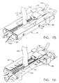
- Figure 15 is a view of the implement 20 as it is holding the graft and target blood vessels, 152 and 150, and after the cassette 60 has been pushed into the frame 40 to a second position.
- the left hook 54 clicks into left hole 66 at this position to provide feedback to the user that the cassette 60 is properly positioned.
- the plow 110 has been advanced in the proximal direction.
- the plow point 122 and upper and lower cutting edges, 116 and 118 have been pushed through the graft and target vessels at their juncture and created a passageway between them.
- the fully advanced plow 110 can be seen after it has cut through the vessels and created a left tissue junction 140 and a right tissue junction 142 (see Figure 17).
- the entire working portion of the cassette 60 including the spiral needles 160 and 162, moved axially as well, thus positioning the spiral needles near the graft and target blood vessels, 152 and 150.
- FIG 17 is shown how the upper rail 114 of the plow 110 has inserted into the second prong 84 of the tissue clip 80.
- the lower rail 112 of the plow 110 has inserted into the first prong 82 of the tissue clip 80. This arrangement occurred as the plow 110 was advanced proximally by the user pushing the cassette 60 into the frame 40.
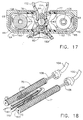
- Figure 18 is shown the left and right drive members, 102 and 104, engaging with the left and right rollers, 71 and 70.
- the left drive shaft 106 slides freely into the left roller hole 73, but because of the non-circular shape of the left roller hole 73 and the similarly shaped drive shaft 106, the rotation of the driveshaft is transmitted to the roller in the direction shown.
- the same arrangement is provided on the right side, except the right roller 70 is rotated in the opposite direction as the left roller 71.
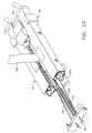
- Figure 19 is a cutaway perspective view of the implement 20 after the spiral needles, 160 and 162, have been fully advanced in the proximal direction.
- a plurality of stitches, 164 have been placed into the left tissue junction 140 and the right tissue junction 142 (not visible) and the graft and target blood vessels have been joined together.
- the number of stitches 164 for this embodiment of the implement 20 can vary depending on the initial size of the graft and target blood vessels, 152 and 150.
- the number and spacing of the stitches can be different from what is shown in Figure 19, as those skilled in the art can see, by varying the number and spacing of needle guiding features of the implement 20, and by varying the spacing between the windings of the spiral needles, 160 and 162.
- Figure 20 depicts the removal of the end cover 62 and the attached plow 110 from the cassette 60. While this is done, the spiral needles 160 and 162 remain in the positions as shown in Figure 19. The end cover 62 is next pulled off the ends of the suture filaments 161 and 163 and discarded.
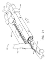
- Figure 21 shows the removal of the joined blood vessels, 150 and 152, from the implement 20 by gently working the implement off the vessel in the direction shown. Other surgical devices or probes may be used during this step to help free the blood vessels from the implement. As the blood vessels are drawn away from the implement, the suture filaments 161 and 163 are pulled through the tissue junctions 140 and 142 until sufficient lengths of proximal filaments is available for completing the anastomosis.
- the anastomosis is completed by severing the proximal filaments 144 near the implement 20, removing the surgical device 10, and tying the two proximal filaments 144 together using a conventional surgeon's knot, and then tying the two distal filaments 146 together, again using a conventional surgeon's knot.
- the order of tying the knots may be reversed. The excess suture filament can then be trimmed away.
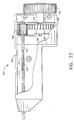
- FIG 22 is a cut away view of the handle 180 of the surgical device 10 of the present invention.
- the handle 180 provides the means to actuate the work portion of the cassette 20 in order to advance the spiral needles, 160 and 162, as already described.
- the handle 180 of this preferred embodiment of the present invention has an elongated, in-line grip with a distal and proximal end.
- the handle includes a control knob 182 which is mounted in the proximal end and is actuated by rotation in the clockwise direction.
- the drive section 130 extends from the distal end.
- the right handle cover 184 is joined to the left handle cover 185 (not shown) by a plurality of fastening pins 197 which press tightly into mating bosses (not shown) on the inside of the left handle cover 185.
- fastening methods may be used, such as gripper pins, ultrasonically welded joints, screws, and the like.
- the two flexible drive members, 104 and 102, of the drive section 130 extend into the handle 180.
- the right drive member 104 has a flexible wire shaft 132 covered by a sheath 133.
- the left drive member 102 has a flexible shaft wire 134 covered by a sheath 135.
- the proximal end of the right drive member 104 is attached to a right pinion gear 188 which is rotatably mounted between handle ribs 191 and 192.
- right pinion gear rotates about center 189 and meshes with a left pinion gear 193 which is attached to the distal end of left drive member 102 and is rotatably mounted also between handle ribs 191 and 192.
- Left pinion gear 193 rotates about center 194.
- the left pinion gear 194 also meshes with drive gear 186.
- Drive gear 186 is mounted between ribs 191 and 192 and is attached to a control knob boss 196 by a screw 190. Rotation of the control knob 182, therefore, in the clockwise direction causes the drive gear and right pinion gear 188 to rotate in the clockwise direction and the left pinion gear 193 to rotate in the counterclockwise direction.
- This gearing method provides the oppositely directed rotation of the drive members, 104 and 102.
- Figure 23 shows a proximal end elevational view of the handle, with a portion of the handle covers, 184 and 185, removed to view the internal components.
- Counterclockwise rotation of the control knob is not desirable in the preferred embodiment of the surgical device 10 because this rotational direction would not serve. to advance the spiral needles, 160 and 162, in the proximal direction as required to join the blood vessels with suture filaments. Therefore, the counterclockwise rotation of the control knob is prevented by a one-way pawl spring 198 mounted to the inside of left handle cover 184 and interacting with drive gear 186. However, the surgical device 10 would still be operational without the pawl spring 198. Also, a manual release could also be provided on the handle to allow the surgeon to turn "off and on” the interaction of the pawl spring 198 with the drive gear 186.
- a flexible tip 200 is shown attached to the first prong 82.
- the flexible tip 82 is an elongated filament which may be solid or tubular, and is made of a flexible, biocompatible polymer such as polyethylene. It is attached to the first prong 82 using preferably a biocompatible adhesive, although mechanical and other methods of attachment are well-known to those skilled in the art.
- the flexible tip 200 serves as a means for facilitating the introduction of the first prong into an aperture of a hollow organ, by providing a steerable and atraumatic extension to the rigid first prong 82.
- a similar flexible tip may also be provided on the second prong 84.
- the first prong 82 of the alternate embodiment of tissue clip 80 is shown inserted into a target blood vessel 150, such as a coronary artery.
- a target blood vessel 150 such as a coronary artery.
- the second embodiment of the tissue clip 80 requires the creation with a surgical scalpel of an aperture in the wall of the target blood vessel 150, prior to insertion of the flexible tip 200. For the first embodiment shown in Figure 6, creation of an aperture is not necessary.
Applications Claiming Priority (2)
| Application Number | Priority Date | Filing Date | Title |
|---|---|---|---|
| US09/031,346 US6015416A (en) | 1998-02-26 | 1998-02-26 | Surgical anastomosis instrument |
| US31346 | 1998-02-26 |
Publications (2)
| Publication Number | Publication Date |
|---|---|
| EP0938870A1 true EP0938870A1 (de) | 1999-09-01 |
| EP0938870B1 EP0938870B1 (de) | 2006-05-17 |
Family
ID=21858928
Family Applications (1)
| Application Number | Title | Priority Date | Filing Date |
|---|---|---|---|
| EP99301416A Expired - Lifetime EP0938870B1 (de) | 1998-02-26 | 1999-02-25 | Instrument zur chirurgischen Anastomose |
Country Status (7)
| Country | Link |
|---|---|
| US (2) | US6015416A (de) |
| EP (1) | EP0938870B1 (de) |
| JP (1) | JPH11276494A (de) |
| AU (1) | AU742319B2 (de) |
| CA (1) | CA2262993A1 (de) |
| DE (1) | DE69931293T2 (de) |
| ES (1) | ES2264243T3 (de) |
Cited By (21)
| Publication number | Priority date | Publication date | Assignee | Title |
|---|---|---|---|---|
| WO2001008601A3 (en) * | 1999-07-28 | 2001-08-16 | Vascular Innovations Inc | Anastomosis system and method of use |
| US6302892B1 (en) | 1999-08-04 | 2001-10-16 | Percardia, Inc. | Blood flow conduit delivery system and method of use |
| US6371964B1 (en) | 1999-05-18 | 2002-04-16 | Vascular Innovations, Inc. | Trocar for use in deploying an anastomosis device and method of performing anastomosis |
| US6461320B1 (en) | 1998-08-12 | 2002-10-08 | Cardica, Inc. | Method and system for attaching a graft to a blood vessel |
| US6471713B1 (en) | 2000-11-13 | 2002-10-29 | Cardica, Inc. | System for deploying an anastomosis device and method of performing anastomosis |
| US6497710B2 (en) | 1998-08-12 | 2002-12-24 | Cardica, Inc. | Method and system for attaching a graft to a blood vessel |
| US6537288B2 (en) | 1999-05-18 | 2003-03-25 | Cardica, Inc. | Implantable medical device such as an anastomosis device |
| US6623494B1 (en) | 1999-04-16 | 2003-09-23 | Integrated Vascular Interventional Technologies, L.C. (Ivit, Lc) | Methods and systems for intraluminally directed vascular anastomosis |
| US6673088B1 (en) | 1999-05-18 | 2004-01-06 | Cardica, Inc. | Tissue punch |
| US6719769B2 (en) | 1999-11-15 | 2004-04-13 | Cardica, Inc. | Integrated anastomosis tool with graft vessel attachment device and cutting device |
| US6776785B1 (en) | 2000-10-12 | 2004-08-17 | Cardica, Inc. | Implantable superelastic anastomosis device |
| WO2005000127A1 (de) * | 2003-06-27 | 2005-01-06 | Zürcher Hochschule Winterthur | Apparat zur durchführung einer anastomose |
| WO2006063479A1 (de) * | 2004-12-17 | 2006-06-22 | Zürcher Hochschule Winterthur | Vorrichtung zur durchführung einer anastomose |
| CN101991449A (zh) * | 2009-08-14 | 2011-03-30 | Tyco医疗健康集团 | 医疗装置的组织紧固系统 |
| US8162963B2 (en) | 2004-06-17 | 2012-04-24 | Maquet Cardiovascular Llc | Angled anastomosis device, tools and method of using |
| US9622748B2 (en) | 1999-07-28 | 2017-04-18 | Dextera Surgical Inc. | Anastomosis system with flexible shaft |
| US9655618B2 (en) | 2007-09-06 | 2017-05-23 | Dextera Surgical Inc. | Surgical method utilizing a true multiple-fire surgical stapler |
| US10405856B2 (en) | 2007-09-06 | 2019-09-10 | Aesculap Ag | Method for surgical stapling |
| EP3572005A3 (de) * | 2016-10-17 | 2019-12-25 | LSI Solutions, Inc. | Kassette als bestandteil einer prothetischen nahtvorrichtung |
| EP4115819A1 (de) * | 2021-07-07 | 2023-01-11 | LSI Solutions, Inc. | Vorrichtung für die herzchirurgie |
| EP4065008A4 (de) * | 2020-03-03 | 2023-12-20 | Wright Medical Technology, Inc. | Selbstgenähtes allotransplantat |
Families Citing this family (116)
| Publication number | Priority date | Publication date | Assignee | Title |
|---|---|---|---|---|
| US20020019642A1 (en) * | 1996-07-23 | 2002-02-14 | Keith Milliman | Anastomosis instrument and method for performing same |
| US7223273B2 (en) * | 1996-07-23 | 2007-05-29 | Tyco Healthcare Group Lp | Anastomosis instrument and method for performing same |
| WO2001052748A2 (en) * | 2000-01-18 | 2001-07-26 | Tyco Healthcare Group Lp | Anastomosis instrument and method for performing same |
| US6440146B2 (en) | 1996-07-23 | 2002-08-27 | United States Surgical Corporation | Anastomosis instrument and method |
| US6332889B1 (en) * | 1998-08-27 | 2001-12-25 | Onux Medical, Inc. | Surgical suturing instrument and method of use |
| US6626921B2 (en) | 1999-04-16 | 2003-09-30 | Integrated Vascular Interventional Technologies, L.C. | Externally positioned anvil apparatus for cutting anastomosis |
| US7981126B2 (en) * | 1999-04-16 | 2011-07-19 | Vital Access Corporation | Locking compression plate anastomosis apparatus |
| US6743244B2 (en) | 1999-04-16 | 2004-06-01 | Integrated Vascular Interventional Technologies, L.C. | Soft anvil apparatus for cutting anastomosis fenestra |
| US7048751B2 (en) * | 2001-12-06 | 2006-05-23 | Cardica, Inc. | Implantable medical device such as an anastomosis device |
| AU5150600A (en) * | 1999-05-18 | 2000-12-05 | Vascular Innovations, Inc. | Tissue punch |
| US6179849B1 (en) * | 1999-06-10 | 2001-01-30 | Vascular Innovations, Inc. | Sutureless closure for connecting a bypass graft to a target vessel |
| US7682368B1 (en) * | 1999-07-28 | 2010-03-23 | Cardica, Inc. | Anastomosis tool actuated with stored energy |
| US7285131B1 (en) * | 1999-07-28 | 2007-10-23 | Cardica, Inc. | System for performing anastomosis |
| US7850703B2 (en) | 1999-07-28 | 2010-12-14 | Cardica, Inc. | System for performing anastomosis |
| US7300444B1 (en) * | 1999-07-28 | 2007-11-27 | Cardica, Inc. | Surgical system and method for connecting hollow tissue structures |
| US7063712B2 (en) * | 2001-04-27 | 2006-06-20 | Cardica, Inc. | Anastomosis method |
| US7766924B1 (en) | 1999-07-28 | 2010-08-03 | Cardica, Inc. | System for performing anastomosis |
| US6527785B2 (en) * | 1999-08-03 | 2003-03-04 | Onux Medical, Inc. | Surgical suturing instrument and method of use |
| AU7341800A (en) * | 1999-09-01 | 2001-03-26 | Origin Medsystems, Inc. | Method and apparatus for performing anastomosis |
| US6679895B1 (en) * | 1999-11-05 | 2004-01-20 | Onux Medical, Inc. | Apparatus and method for placing suture wires into tissue for the approximation and tensioning of tissue |
| US6736825B2 (en) * | 1999-12-14 | 2004-05-18 | Integrated Vascular Interventional Technologies, L C (Ivit Lc) | Paired expandable anastomosis devices and related methods |
| US6514263B1 (en) | 2000-08-30 | 2003-02-04 | Ethicon Endo-Surgery, Inc. | Helical needle and suture combination having a strain relief element |
| US6613058B1 (en) | 2000-08-30 | 2003-09-02 | Ethicon Endo-Surgery, Inc. | Anastomosis device having needle receiver for capturing the needle |
| US6520973B1 (en) | 2000-08-30 | 2003-02-18 | Ethicon Endo-Surgery, Inc. | Anastomosis device having an improved needle driver |
| US6530932B1 (en) | 2000-08-30 | 2003-03-11 | Ethicon Endo-Surgery, Inc. | Anastomosis device having improved tissue presentation |
| WO2002056748A2 (en) | 2000-10-20 | 2002-07-25 | Onux Medical, Inc. | Surgical suturing instrument and method of use |
| US20050234483A1 (en) * | 2000-11-06 | 2005-10-20 | Cardica, Inc. | Unitary anastomosis device |
| US20020095166A1 (en) * | 2001-01-16 | 2002-07-18 | Jaime Vargas | Incision tensioning system and method for using the same |
| US7131980B1 (en) * | 2001-01-18 | 2006-11-07 | Dvl Acquisitions Sub, Inc. | Surgical suturing instrument and method of use |
| JP4130584B2 (ja) * | 2001-01-24 | 2008-08-06 | タイコ ヘルスケア グループ リミテッド パートナーシップ | 吻合器具および吻合を実施する方法 |
| US6953464B2 (en) * | 2001-02-21 | 2005-10-11 | Novare Surgical Systems, Inc. | Anastomosis occlusion device |
| US6620177B2 (en) | 2001-02-15 | 2003-09-16 | Novare Surgical Systems, Inc. | Anastomosis occlusion device |
| US6890338B1 (en) * | 2001-02-27 | 2005-05-10 | Origin Medsystems, Inc. | Method and apparatus for performing anastomosis using ring having tines with weak sections |
| US6902570B2 (en) * | 2001-06-08 | 2005-06-07 | Rolf Dieter Schraft | Device and method for connecting hollow organs and/or sealing wall defects in hollow organs |
| US7011668B2 (en) * | 2001-07-23 | 2006-03-14 | Dvl Acquistion Sub, Inc. | Surgical suturing instrument and method of use |
| WO2003024300A2 (en) * | 2001-09-14 | 2003-03-27 | Onux Medical, Inc. | Surgical suturing instrument and method of use |
| US6746456B2 (en) * | 2001-09-28 | 2004-06-08 | Ethicon, Inc. | Needle array suturing/sewing anastomosis device and method for anastomosis |
| US6860891B2 (en) * | 2001-09-28 | 2005-03-01 | Ethicen, Inc. | Arrangement and method for vascular anastomosis |
| US7461767B2 (en) * | 2005-06-03 | 2008-12-09 | Tyco Healthcare Group Lp | Battery powered surgical instrument |
| US7464847B2 (en) | 2005-06-03 | 2008-12-16 | Tyco Healthcare Group Lp | Surgical stapler with timer and feedback display |
| US10285694B2 (en) | 2001-10-20 | 2019-05-14 | Covidien Lp | Surgical stapler with timer and feedback display |
| US7335216B2 (en) * | 2002-01-22 | 2008-02-26 | Cardica, Inc. | Tool for creating an opening in tissue |
| US7029482B1 (en) * | 2002-01-22 | 2006-04-18 | Cardica, Inc. | Integrated anastomosis system |
| US8012164B1 (en) | 2002-01-22 | 2011-09-06 | Cardica, Inc. | Method and apparatus for creating an opening in the wall of a tubular vessel |
| US7223274B2 (en) * | 2002-01-23 | 2007-05-29 | Cardica, Inc. | Method of performing anastomosis |
| EP1330986B1 (de) * | 2002-01-25 | 2009-12-09 | Terumo Kabushiki Kaisha | Vorrichtung zum Einschneiden von Blutgefässen |
| WO2003082125A1 (en) * | 2002-03-25 | 2003-10-09 | Onux Medical, Inc. | Surgical suturing instrument and method of use |
| US7530987B1 (en) | 2002-04-24 | 2009-05-12 | Cardica, Inc. | Surgical tool for creating an incision in a tubular vessel |
| CA2484870A1 (en) * | 2002-05-17 | 2003-11-27 | Dvl Acquisition Sub, Inc. | Surgical suturing instrument and method of use |
| AU2003241521A1 (en) * | 2002-05-17 | 2003-12-02 | Onux Medical, Inc. | Surgical suturing instrument and method of use |
| US7153286B2 (en) * | 2002-05-24 | 2006-12-26 | Baxter International Inc. | Automated dialysis system |
| US6769594B2 (en) | 2002-05-31 | 2004-08-03 | Tyco Healthcare Group, Lp | End-to-end anastomosis instrument and method for performing same |
| US7195142B2 (en) * | 2003-05-30 | 2007-03-27 | Tyco Healthcare Group Lp | End-to-end anastomosis instrument and method for performing same |
| US7267682B1 (en) | 2002-12-04 | 2007-09-11 | Cardica, Inc. | Anastomosis staple |
| ES2279231T3 (es) * | 2003-05-09 | 2007-08-16 | Tyco Healthcare Group Lp | Grapa anastomotica con tubo capilar que dispensa fluidos. |
| US8574246B1 (en) | 2004-06-25 | 2013-11-05 | Cardica, Inc. | Compliant anastomosis system utilizing suture |
| US7794471B1 (en) | 2003-06-26 | 2010-09-14 | Cardica, Inc. | Compliant anastomosis system |
| US20050010241A1 (en) * | 2003-07-09 | 2005-01-13 | Keith Milliman | Anastomosis instrument and method for performing same |
| US8080023B2 (en) | 2003-12-12 | 2011-12-20 | Vitalitec International, Inc. | Device and method for performing multiple anastomoses |
| US7585306B2 (en) * | 2003-12-24 | 2009-09-08 | Maquet Cardiovascular Llc | Anastomosis device, tools and methods of using |
| US20050149071A1 (en) * | 2003-12-24 | 2005-07-07 | Ryan Abbott | Anastomosis device, tools and method of using |
| US20080269784A1 (en) * | 2003-12-24 | 2008-10-30 | Ryan Abbott | Anastomosis device, tools and methods of using |
| US8114110B2 (en) | 2004-09-22 | 2012-02-14 | St. Jude Medical, Atrial Fibrillation Division, Inc. | Transseptal puncture needle and needle assemblies |
| US9326756B2 (en) * | 2006-05-17 | 2016-05-03 | St. Jude Medical, Atrial Fibrillation Division, Inc. | Transseptal catheterization assembly and methods |
| US8906039B2 (en) * | 2005-03-21 | 2014-12-09 | Design Standards Corporation | Suturing device |
| WO2006127985A2 (en) * | 2005-05-26 | 2006-11-30 | Texas Heart Institute | Surgical system and method for attaching a prosthetic vessel to a hollow structure |
| US11291443B2 (en) | 2005-06-03 | 2022-04-05 | Covidien Lp | Surgical stapler with timer and feedback display |
| US20070142850A1 (en) * | 2005-12-15 | 2007-06-21 | David Fowler | Compression anastomosis device |
| US7815652B2 (en) * | 2006-03-21 | 2010-10-19 | Ethicon Endo-Surgery, Inc. | Surgical fastener and instrument |
| US7431188B1 (en) | 2007-03-15 | 2008-10-07 | Tyco Healthcare Group Lp | Surgical stapling apparatus with powered articulation |
| US7950560B2 (en) | 2007-04-13 | 2011-05-31 | Tyco Healthcare Group Lp | Powered surgical instrument |
| US11259802B2 (en) | 2007-04-13 | 2022-03-01 | Covidien Lp | Powered surgical instrument |
| US8800837B2 (en) | 2007-04-13 | 2014-08-12 | Covidien Lp | Powered surgical instrument |
| US20080255413A1 (en) | 2007-04-13 | 2008-10-16 | Michael Zemlok | Powered surgical instrument |
| US7823760B2 (en) | 2007-05-01 | 2010-11-02 | Tyco Healthcare Group Lp | Powered surgical stapling device platform |
| US7931660B2 (en) | 2007-05-10 | 2011-04-26 | Tyco Healthcare Group Lp | Powered tacker instrument |
| US10004507B2 (en) | 2007-06-18 | 2018-06-26 | Asfora Ip, Llc | Vascular anastomosis device and method |
| US9504469B2 (en) | 2007-06-18 | 2016-11-29 | Asfora Ip, Llc | Vascular anastomosis device and method |
| US8361092B1 (en) | 2007-06-18 | 2013-01-29 | Wilson T. Asfora | Vascular anastomosis device and method |
| US9168039B1 (en) | 2007-09-06 | 2015-10-27 | Cardica, Inc. | Surgical stapler with staples of different sizes |
| US8197464B2 (en) * | 2007-10-19 | 2012-06-12 | Cordis Corporation | Deflecting guide catheter for use in a minimally invasive medical procedure for the treatment of mitral valve regurgitation |
| US8226709B2 (en) | 2007-10-19 | 2012-07-24 | Cordis Corporation | Method and system for plicating tissue in a minimally invasive medical procedure for the treatment of mitral valve regurgitation |
| US7922063B2 (en) | 2007-10-31 | 2011-04-12 | Tyco Healthcare Group, Lp | Powered surgical instrument |
| US8771312B1 (en) | 2007-11-05 | 2014-07-08 | Cardica, Inc. | Anastomosis fasteners |
| DE102009009925B4 (de) | 2009-02-20 | 2018-09-13 | Fraunhofer-Gesellschaft zur Förderung der angewandten Forschung e.V. | Vorrichtung zum Durchführen einer Anastomose |
| US8167898B1 (en) | 2009-05-05 | 2012-05-01 | Cardica, Inc. | Flexible cutter for surgical stapler |
| US8821514B2 (en) * | 2009-06-08 | 2014-09-02 | Covidien Lp | Powered tack applier |
| US8413872B2 (en) | 2009-10-28 | 2013-04-09 | Covidien Lp | Surgical fastening apparatus |
| JP5871915B2 (ja) | 2010-06-11 | 2016-03-01 | アントラージュ メディカル テクノロジーズ,インコーポレイテッドEntourage Medical Technologies,Inc. | 経心尖的アクセスおよび閉鎖のためのシステムおよび方法 |
| US9161778B2 (en) | 2010-06-11 | 2015-10-20 | Entourage Medical Technologies, Inc. | System and method for transapical access and closure |
| DE102010035470B4 (de) | 2010-08-26 | 2015-08-13 | Fraunhofer-Gesellschaft zur Förderung der angewandten Forschung e.V. | Vorrichtung zum Durchführen einer Seit-zu-Seit- Anastomose |
| US8939936B2 (en) * | 2010-09-20 | 2015-01-27 | Entorurage Medical Technologies, Inc. | System for providing surgical access |
| JP2016537162A (ja) | 2013-10-29 | 2016-12-01 | アントラージュ メディカル テクノロジーズ,インコーポレイテッドEntourage Medical Technologies,Inc. | 外科手術アクセスを提供するためのシステム |
| US10092286B2 (en) | 2015-05-27 | 2018-10-09 | Covidien Lp | Suturing loading unit |
| US11311285B2 (en) * | 2015-12-21 | 2022-04-26 | Lsi Solutions, Inc. | Prosthetic suturing device and methods thereof |
| US11311295B2 (en) | 2017-05-15 | 2022-04-26 | Covidien Lp | Adaptive powered stapling algorithm with calibration factor |
| US10987104B2 (en) | 2017-10-30 | 2021-04-27 | Covidien Lp | Apparatus for endoscopic procedures |
| US11207066B2 (en) | 2017-10-30 | 2021-12-28 | Covidien Lp | Apparatus for endoscopic procedures |
| US11116506B2 (en) * | 2018-05-08 | 2021-09-14 | Gyrus Acmi, Inc. | Partial eversion anastomosis juncture formation and suturing |
| US11497490B2 (en) | 2018-07-09 | 2022-11-15 | Covidien Lp | Powered surgical devices including predictive motor control |
| US11197734B2 (en) | 2018-10-30 | 2021-12-14 | Covidien Lp | Load sensing devices for use in surgical instruments |
| US11369372B2 (en) | 2018-11-28 | 2022-06-28 | Covidien Lp | Surgical stapler adapter with flexible cable assembly, flexible fingers, and contact clips |
| US11202635B2 (en) | 2019-02-04 | 2021-12-21 | Covidien Lp | Programmable distal tilt position of end effector for powered surgical devices |
| US11376006B2 (en) | 2019-02-06 | 2022-07-05 | Covidien Lp | End effector force measurement with digital drive circuit |
| US11219461B2 (en) | 2019-03-08 | 2022-01-11 | Covidien Lp | Strain gauge stabilization in a surgical device |
| US11439397B2 (en) * | 2019-03-27 | 2022-09-13 | Gyrus Acmi, Inc. | Suturing apparatus and method |
| GB2590138B (en) * | 2019-09-30 | 2023-08-02 | Gyrus Acmi Inc | Suturing apparatus and method |
| US11458244B2 (en) | 2020-02-07 | 2022-10-04 | Covidien Lp | Irrigating surgical apparatus with positive pressure fluid |
| US11553913B2 (en) | 2020-02-11 | 2023-01-17 | Covidien Lp | Electrically-determining tissue cut with surgical stapling apparatus |
| DE102021107650A1 (de) * | 2020-03-31 | 2021-09-30 | Gyrus Acmi, Inc. D/B/A Olympus Surgical Technologies America | Bewegbare nähvorrichtung und verfahren |
| US11622768B2 (en) | 2020-07-13 | 2023-04-11 | Covidien Lp | Methods and structure for confirming proper assembly of powered surgical stapling systems |
| US11653919B2 (en) | 2020-11-24 | 2023-05-23 | Covidien Lp | Stapler line reinforcement continuity |
| US11744580B2 (en) | 2020-11-24 | 2023-09-05 | Covidien Lp | Long stapler reloads with continuous cartridge |
| US11684362B2 (en) | 2021-06-07 | 2023-06-27 | Covidien Lp | Handheld electromechanical surgical system |
| US11771432B2 (en) | 2021-06-29 | 2023-10-03 | Covidien Lp | Stapling and cutting to default values in the event of strain gauge data integrity loss |
| US11832823B2 (en) | 2022-02-08 | 2023-12-05 | Covidien Lp | Determination of anvil release during anastomosis |
Citations (8)
| Publication number | Priority date | Publication date | Assignee | Title |
|---|---|---|---|---|
| US3316914A (en) * | 1963-02-14 | 1967-05-02 | Michael B Collito | Surgical methods and devices for anastomosis |
| GB1181563A (en) * | 1966-03-08 | 1970-02-18 | Pfau Wanfried G M B H H | A Device for Anastomosing Canalicular Organs. |
| US3561448A (en) * | 1968-08-30 | 1971-02-09 | Jacob Peternel | Blood vessel suturing apparatus |
| US4803984A (en) | 1987-07-06 | 1989-02-14 | Montefiore Hospital Association Of Western Pennsylvania | Method for performing small vessel anastomosis |
| WO1995017128A1 (en) * | 1993-12-23 | 1995-06-29 | Oticon A/S | Method, instrument and anastomotic fitting for use when performing an end-to-side anastomosis |
| US5545148A (en) | 1992-10-24 | 1996-08-13 | Wurster; Helmut | Endoscopic sewing instrument |
| US5571090A (en) | 1994-10-07 | 1996-11-05 | United States Surgical Corporation | Vascular suturing apparatus |
| WO1997012555A2 (en) * | 1995-10-03 | 1997-04-10 | Cedars-Sinai Medical Center | Devices for performing vascular anastomoses |
Family Cites Families (27)
| Publication number | Priority date | Publication date | Assignee | Title |
|---|---|---|---|---|
| US1181563A (en) * | 1915-04-09 | 1916-05-02 | Charles Becker | Rail-clamp. |
| US3019789A (en) * | 1958-06-30 | 1962-02-06 | Jules L Whitehill | Anastomosis clamp |
| US3019790A (en) * | 1960-07-15 | 1962-02-06 | Robert J Militana | Combination hemostat and intravenous needle |
| SU715082A1 (ru) * | 1977-01-24 | 1980-02-15 | Всесоюзный научно-исследовательский и испытательный институт медицинской техники | Хирургический сшивающий аппарат |
| US4345600A (en) * | 1980-08-04 | 1982-08-24 | Senco Products, Inc. | Purse-stringer |
| US4368736A (en) * | 1980-11-17 | 1983-01-18 | Kaster Robert L | Anastomotic fitting |
| US4366819A (en) * | 1980-11-17 | 1983-01-04 | Kaster Robert L | Anastomotic fitting |
| US4470415A (en) * | 1982-08-19 | 1984-09-11 | The Johns Hopkins University | Sutureless vascular anastomosis means and method |
| US4657019A (en) * | 1984-04-10 | 1987-04-14 | Idea Research Investment Fund, Inc. | Anastomosis devices and kits |
| US4593693A (en) * | 1985-04-26 | 1986-06-10 | Schenck Robert R | Methods and apparatus for anastomosing living vessels |
| US4917114A (en) * | 1986-10-17 | 1990-04-17 | United States Surgical Corporation | Surgical fastener and surgical stapling apparatus |
| US4749114A (en) * | 1986-11-10 | 1988-06-07 | United States Surgical Corporation | Purse string applicator and method of affixing a purse string |
| US4773420A (en) * | 1987-06-22 | 1988-09-27 | U.S. Surgical Corporation | Purse string applicator |
| IT1216042B (it) * | 1988-03-09 | 1990-02-22 | Carlo Rebuffat | Strumento automatico per suture a borsa di tabacco ad uso chirurgico. |
| US4931057A (en) * | 1988-03-29 | 1990-06-05 | Pfizer Hospital Products Group, Inc. | Compression anastomosis coupling assembly |
| US4997439A (en) * | 1989-01-26 | 1991-03-05 | Chen Fusen H | Surgical closure or anastomotic device |
| US4930502A (en) * | 1989-01-26 | 1990-06-05 | Chen Fusen H | Anastomosis device |
| US5089008A (en) * | 1989-01-26 | 1992-02-18 | Chen Fusen H | Surgical closure means for anastomotic device |
| US5041127A (en) * | 1989-02-27 | 1991-08-20 | Troutman Richard C | Offset point surgical needle |
| US5425737A (en) * | 1992-04-08 | 1995-06-20 | American Cyanamid Co. | Surgical purse string suturing instrument and method |
| US5411481A (en) * | 1992-04-08 | 1995-05-02 | American Cyanamid Co. | Surgical purse string suturing instrument and method |
| US5188636A (en) * | 1992-05-07 | 1993-02-23 | Ethicon, Inc. | Purse string suture instrument |
| US5356424A (en) * | 1993-02-05 | 1994-10-18 | American Cyanamid Co. | Laparoscopic suturing device |
| US5520703A (en) * | 1993-06-07 | 1996-05-28 | Essig; Mitchell N. | Laparoscopic deschamp and associated suturing technique |
| US5782749A (en) * | 1994-05-10 | 1998-07-21 | Riza; Erol D. | Laparoscopic surgical instrument with adjustable grip |
| US5562685A (en) * | 1994-09-16 | 1996-10-08 | General Surgical Innovations, Inc. | Surgical instrument for placing suture or fasteners |
| US5695504A (en) * | 1995-02-24 | 1997-12-09 | Heartport, Inc. | Devices and methods for performing a vascular anastomosis |
-
1998
- 1998-02-26 US US09/031,346 patent/US6015416A/en not_active Expired - Lifetime
-
1999
- 1999-02-16 AU AU17342/99A patent/AU742319B2/en not_active Expired
- 1999-02-24 CA CA002262993A patent/CA2262993A1/en not_active Abandoned
- 1999-02-25 DE DE69931293T patent/DE69931293T2/de not_active Expired - Lifetime
- 1999-02-25 JP JP11048876A patent/JPH11276494A/ja active Pending
- 1999-02-25 EP EP99301416A patent/EP0938870B1/de not_active Expired - Lifetime
- 1999-02-25 ES ES99301416T patent/ES2264243T3/es not_active Expired - Lifetime
- 1999-10-05 US US09/412,276 patent/US6187019B1/en not_active Expired - Lifetime
Patent Citations (8)
| Publication number | Priority date | Publication date | Assignee | Title |
|---|---|---|---|---|
| US3316914A (en) * | 1963-02-14 | 1967-05-02 | Michael B Collito | Surgical methods and devices for anastomosis |
| GB1181563A (en) * | 1966-03-08 | 1970-02-18 | Pfau Wanfried G M B H H | A Device for Anastomosing Canalicular Organs. |
| US3561448A (en) * | 1968-08-30 | 1971-02-09 | Jacob Peternel | Blood vessel suturing apparatus |
| US4803984A (en) | 1987-07-06 | 1989-02-14 | Montefiore Hospital Association Of Western Pennsylvania | Method for performing small vessel anastomosis |
| US5545148A (en) | 1992-10-24 | 1996-08-13 | Wurster; Helmut | Endoscopic sewing instrument |
| WO1995017128A1 (en) * | 1993-12-23 | 1995-06-29 | Oticon A/S | Method, instrument and anastomotic fitting for use when performing an end-to-side anastomosis |
| US5571090A (en) | 1994-10-07 | 1996-11-05 | United States Surgical Corporation | Vascular suturing apparatus |
| WO1997012555A2 (en) * | 1995-10-03 | 1997-04-10 | Cedars-Sinai Medical Center | Devices for performing vascular anastomoses |
Cited By (33)
| Publication number | Priority date | Publication date | Assignee | Title |
|---|---|---|---|---|
| US6461320B1 (en) | 1998-08-12 | 2002-10-08 | Cardica, Inc. | Method and system for attaching a graft to a blood vessel |
| US6805708B1 (en) | 1998-08-12 | 2004-10-19 | Cardica, Inc. | Method and system for attaching a graft to a blood vessel |
| US6497710B2 (en) | 1998-08-12 | 2002-12-24 | Cardica, Inc. | Method and system for attaching a graft to a blood vessel |
| US6623494B1 (en) | 1999-04-16 | 2003-09-23 | Integrated Vascular Interventional Technologies, L.C. (Ivit, Lc) | Methods and systems for intraluminally directed vascular anastomosis |
| US6419681B1 (en) | 1999-05-18 | 2002-07-16 | Cardica, Inc. | Implantable medical device such as an anastomosis device |
| US6537288B2 (en) | 1999-05-18 | 2003-03-25 | Cardica, Inc. | Implantable medical device such as an anastomosis device |
| US6428550B1 (en) | 1999-05-18 | 2002-08-06 | Cardica, Inc. | Sutureless closure and deployment system for connecting blood vessels |
| US6786914B1 (en) | 1999-05-18 | 2004-09-07 | Cardica, Inc. | Sutureless closure and deployment system for connecting blood vessels |
| US6673088B1 (en) | 1999-05-18 | 2004-01-06 | Cardica, Inc. | Tissue punch |
| US6652541B1 (en) | 1999-05-18 | 2003-11-25 | Cardica, Inc | Method of sutureless closure for connecting blood vessels |
| US6371964B1 (en) | 1999-05-18 | 2002-04-16 | Vascular Innovations, Inc. | Trocar for use in deploying an anastomosis device and method of performing anastomosis |
| US6478804B2 (en) | 1999-07-28 | 2002-11-12 | Cardica, Inc. | Anastomosis system and method for controlling a tissue site |
| US6391038B2 (en) | 1999-07-28 | 2002-05-21 | Cardica, Inc. | Anastomosis system and method for controlling a tissue site |
| DE10084856B4 (de) * | 1999-07-28 | 2010-08-05 | Cardica, Inc. (n.d.Ges.d.Staates Delaware), Menlo Park | Anastomosesystem zum Verbinden eines Transplantatblutgefäßes mit einem Zielblutgefäß |
| WO2001008601A3 (en) * | 1999-07-28 | 2001-08-16 | Vascular Innovations Inc | Anastomosis system and method of use |
| US6398797B2 (en) | 1999-07-28 | 2002-06-04 | Cardica, Inc. | Tissue bonding system and method for controlling a tissue site during anastomosis |
| US9622748B2 (en) | 1999-07-28 | 2017-04-18 | Dextera Surgical Inc. | Anastomosis system with flexible shaft |
| US6582444B2 (en) | 1999-08-04 | 2003-06-24 | Percardia, Inc. | Blood flow conduit delivery system and method of use |
| US6302892B1 (en) | 1999-08-04 | 2001-10-16 | Percardia, Inc. | Blood flow conduit delivery system and method of use |
| US6719769B2 (en) | 1999-11-15 | 2004-04-13 | Cardica, Inc. | Integrated anastomosis tool with graft vessel attachment device and cutting device |
| US6776785B1 (en) | 2000-10-12 | 2004-08-17 | Cardica, Inc. | Implantable superelastic anastomosis device |
| US6471713B1 (en) | 2000-11-13 | 2002-10-29 | Cardica, Inc. | System for deploying an anastomosis device and method of performing anastomosis |
| WO2005000127A1 (de) * | 2003-06-27 | 2005-01-06 | Zürcher Hochschule Winterthur | Apparat zur durchführung einer anastomose |
| US8162963B2 (en) | 2004-06-17 | 2012-04-24 | Maquet Cardiovascular Llc | Angled anastomosis device, tools and method of using |
| WO2006063479A1 (de) * | 2004-12-17 | 2006-06-22 | Zürcher Hochschule Winterthur | Vorrichtung zur durchführung einer anastomose |
| US9655618B2 (en) | 2007-09-06 | 2017-05-23 | Dextera Surgical Inc. | Surgical method utilizing a true multiple-fire surgical stapler |
| US10405856B2 (en) | 2007-09-06 | 2019-09-10 | Aesculap Ag | Method for surgical stapling |
| CN101991449A (zh) * | 2009-08-14 | 2011-03-30 | Tyco医疗健康集团 | 医疗装置的组织紧固系统 |
| CN101991449B (zh) * | 2009-08-14 | 2014-10-22 | 柯惠Lp公司 | 医疗装置的组织紧固系统 |
| EP3572005A3 (de) * | 2016-10-17 | 2019-12-25 | LSI Solutions, Inc. | Kassette als bestandteil einer prothetischen nahtvorrichtung |
| EP3977941A1 (de) * | 2016-10-17 | 2022-04-06 | LSI Solutions, Inc. | Kassette als bestandteil einer nähvorrichtung und chirurgische nähvorrichtung |
| EP4065008A4 (de) * | 2020-03-03 | 2023-12-20 | Wright Medical Technology, Inc. | Selbstgenähtes allotransplantat |
| EP4115819A1 (de) * | 2021-07-07 | 2023-01-11 | LSI Solutions, Inc. | Vorrichtung für die herzchirurgie |
Also Published As
| Publication number | Publication date |
|---|---|
| EP0938870B1 (de) | 2006-05-17 |
| JPH11276494A (ja) | 1999-10-12 |
| CA2262993A1 (en) | 1999-08-26 |
| US6015416A (en) | 2000-01-18 |
| AU742319B2 (en) | 2001-12-20 |
| AU1734299A (en) | 1999-09-09 |
| US6187019B1 (en) | 2001-02-13 |
| DE69931293D1 (de) | 2006-06-22 |
| DE69931293T2 (de) | 2007-05-24 |
| ES2264243T3 (es) | 2006-12-16 |
Similar Documents
| Publication | Publication Date | Title |
|---|---|---|
| US6015416A (en) | Surgical anastomosis instrument | |
| US6530932B1 (en) | Anastomosis device having improved tissue presentation | |
| US6514263B1 (en) | Helical needle and suture combination having a strain relief element | |
| US6520973B1 (en) | Anastomosis device having an improved needle driver | |
| US6036700A (en) | Surgical anastomosis instrument | |
| EP0931512B1 (de) | Chirurgisches Klammernahtgerät | |
| US6066144A (en) | Surgical anastomosis method | |
| US10729442B2 (en) | Surgical stapler for aortic anastomosis | |
| US6071289A (en) | Surgical device for suturing tissue | |
| US7303570B2 (en) | Anastomosis tool having a connector holder | |
| US6613058B1 (en) | Anastomosis device having needle receiver for capturing the needle | |
| US8475474B2 (en) | Anastomosis method utilizing tool with fluid-driven actuator | |
| US6013027A (en) | Method for using a tissue stabilization device during surgery | |
| US8377082B2 (en) | Methods and apparatus for making precise incisions in body vessels | |
| US7766924B1 (en) | System for performing anastomosis | |
| US6355050B1 (en) | Device and method for suturing tissue | |
| US7300444B1 (en) | Surgical system and method for connecting hollow tissue structures | |
| US20020095164A1 (en) | Device and method for suturing tissue | |
| US20080287967A1 (en) | Device and Methods for Suturing Tissue | |
| US7371243B1 (en) | Surgical apparatus and method for anastomosis | |
| JP2000189425A (ja) | 縫合補助用針ホルダ― |
Legal Events
| Date | Code | Title | Description |
|---|---|---|---|
| PUAI | Public reference made under article 153(3) epc to a published international application that has entered the european phase |
Free format text: ORIGINAL CODE: 0009012 |
|
| AK | Designated contracting states |
Kind code of ref document: A1 Designated state(s): DE ES FR IT NL |
|
| AX | Request for extension of the european patent |
Free format text: AL;LT;LV;MK;RO;SI |
|
| 17P | Request for examination filed |
Effective date: 20000208 |
|
| AKX | Designation fees paid |
Free format text: DE ES FR IT NL |
|
| 17Q | First examination report despatched |
Effective date: 20041209 |
|
| GRAP | Despatch of communication of intention to grant a patent |
Free format text: ORIGINAL CODE: EPIDOSNIGR1 |
|
| GRAS | Grant fee paid |
Free format text: ORIGINAL CODE: EPIDOSNIGR3 |
|
| GRAA | (expected) grant |
Free format text: ORIGINAL CODE: 0009210 |
|
| AK | Designated contracting states |
Kind code of ref document: B1 Designated state(s): DE ES FR IT NL |
|
| PG25 | Lapsed in a contracting state [announced via postgrant information from national office to epo] |
Ref country code: IT Free format text: LAPSE BECAUSE OF FAILURE TO SUBMIT A TRANSLATION OF THE DESCRIPTION OR TO PAY THE FEE WITHIN THE PRE;WARNING: LAPSES OF ITALIAN PATENTS WITH EFFECTIVE DATE BEFORE 2007 MAY HAVE OCCURRED AT ANY TIME BEFORE 2007. THE CORRECT EFFECTIVE DATE MAY BE DIFFERENT FROM THE ONE RECORDED.SCRIBED TIME-LIMIT Effective date: 20060517 |
|
| REF | Corresponds to: |
Ref document number: 69931293 Country of ref document: DE Date of ref document: 20060622 Kind code of ref document: P |
|
| REG | Reference to a national code |
Ref country code: ES Ref legal event code: FG2A Ref document number: 2264243 Country of ref document: ES Kind code of ref document: T3 |
|
| ET | Fr: translation filed | ||
| PLBE | No opposition filed within time limit |
Free format text: ORIGINAL CODE: 0009261 |
|
| STAA | Information on the status of an ep patent application or granted ep patent |
Free format text: STATUS: NO OPPOSITION FILED WITHIN TIME LIMIT |
|
| 26N | No opposition filed |
Effective date: 20070220 |
|
| REG | Reference to a national code |
Ref country code: FR Ref legal event code: PLFP Year of fee payment: 18 |
|
| REG | Reference to a national code |
Ref country code: FR Ref legal event code: PLFP Year of fee payment: 19 |
|
| REG | Reference to a national code |
Ref country code: FR Ref legal event code: PLFP Year of fee payment: 20 |
|
| PGFP | Annual fee paid to national office [announced via postgrant information from national office to epo] |
Ref country code: NL Payment date: 20180214 Year of fee payment: 20 |
|
| PGFP | Annual fee paid to national office [announced via postgrant information from national office to epo] |
Ref country code: ES Payment date: 20180301 Year of fee payment: 20 Ref country code: DE Payment date: 20180214 Year of fee payment: 20 |
|
| PGFP | Annual fee paid to national office [announced via postgrant information from national office to epo] |
Ref country code: IT Payment date: 20180221 Year of fee payment: 20 Ref country code: FR Payment date: 20180111 Year of fee payment: 20 |
|
| REG | Reference to a national code |
Ref country code: DE Ref legal event code: R071 Ref document number: 69931293 Country of ref document: DE |
|
| REG | Reference to a national code |
Ref country code: NL Ref legal event code: MK Effective date: 20190224 |
|
| REG | Reference to a national code |
Ref country code: ES Ref legal event code: FD2A Effective date: 20200803 |
|
| PG25 | Lapsed in a contracting state [announced via postgrant information from national office to epo] |
Ref country code: ES Free format text: LAPSE BECAUSE OF EXPIRATION OF PROTECTION Effective date: 20190226 |