EP0938246B1 - Verfahren und Anordnung zur Verbindung von Fibre-Channel-Netzen und ATM-Netzen - Google Patents
Verfahren und Anordnung zur Verbindung von Fibre-Channel-Netzen und ATM-Netzen Download PDFInfo
- Publication number
- EP0938246B1 EP0938246B1 EP19990400377 EP99400377A EP0938246B1 EP 0938246 B1 EP0938246 B1 EP 0938246B1 EP 19990400377 EP19990400377 EP 19990400377 EP 99400377 A EP99400377 A EP 99400377A EP 0938246 B1 EP0938246 B1 EP 0938246B1
- Authority
- EP
- European Patent Office
- Prior art keywords
- initialization
- atm network
- network
- fibre channel
- cell
- Prior art date
- Legal status (The legal status is an assumption and is not a legal conclusion. Google has not performed a legal analysis and makes no representation as to the accuracy of the status listed.)
- Expired - Lifetime
Links
Images


Classifications
-
- H—ELECTRICITY
- H04—ELECTRIC COMMUNICATION TECHNIQUE
- H04Q—SELECTING
- H04Q11/00—Selecting arrangements for multiplex systems
- H04Q11/04—Selecting arrangements for multiplex systems for time-division multiplexing
- H04Q11/0428—Integrated services digital network, i.e. systems for transmission of different types of digitised signals, e.g. speech, data, telecentral, television signals
- H04Q11/0478—Provisions for broadband connections
-
- H—ELECTRICITY
- H04—ELECTRIC COMMUNICATION TECHNIQUE
- H04L—TRANSMISSION OF DIGITAL INFORMATION, e.g. TELEGRAPHIC COMMUNICATION
- H04L12/00—Data switching networks
- H04L12/54—Store-and-forward switching systems
- H04L12/56—Packet switching systems
- H04L12/5601—Transfer mode dependent, e.g. ATM
- H04L2012/5603—Access techniques
- H04L2012/5604—Medium of transmission, e.g. fibre, cable, radio
- H04L2012/5605—Fibre
-
- H—ELECTRICITY
- H04—ELECTRIC COMMUNICATION TECHNIQUE
- H04L—TRANSMISSION OF DIGITAL INFORMATION, e.g. TELEGRAPHIC COMMUNICATION
- H04L12/00—Data switching networks
- H04L12/54—Store-and-forward switching systems
- H04L12/56—Packet switching systems
- H04L12/5601—Transfer mode dependent, e.g. ATM
- H04L2012/5614—User Network Interface
- H04L2012/5618—Bridges, gateways [GW] or interworking units [IWU]
-
- H—ELECTRICITY
- H04—ELECTRIC COMMUNICATION TECHNIQUE
- H04L—TRANSMISSION OF DIGITAL INFORMATION, e.g. TELEGRAPHIC COMMUNICATION
- H04L12/00—Data switching networks
- H04L12/54—Store-and-forward switching systems
- H04L12/56—Packet switching systems
- H04L12/5601—Transfer mode dependent, e.g. ATM
- H04L2012/5625—Operations, administration and maintenance [OAM]
- H04L2012/5627—Fault tolerance and recovery
-
- H—ELECTRICITY
- H04—ELECTRIC COMMUNICATION TECHNIQUE
- H04L—TRANSMISSION OF DIGITAL INFORMATION, e.g. TELEGRAPHIC COMMUNICATION
- H04L12/00—Data switching networks
- H04L12/54—Store-and-forward switching systems
- H04L12/56—Packet switching systems
- H04L12/5601—Transfer mode dependent, e.g. ATM
- H04L2012/5638—Services, e.g. multimedia, GOS, QOS
- H04L2012/5646—Cell characteristics, e.g. loss, delay, jitter, sequence integrity
- H04L2012/5652—Cell construction, e.g. including header, packetisation, depacketisation, assembly, reassembly
- H04L2012/5653—Cell construction, e.g. including header, packetisation, depacketisation, assembly, reassembly using the ATM adaptation layer [AAL]
Definitions
- the present invention relates to an apparatus for bridging an Asynchronous Transfer Mode (ATM) network with Fibre Channel networks to construct an FC/ATM composite network, and a method for detecting abnormalities in the inter-network bridging apparatus and controlling the process of initialization of Fibre Channel networks during the recovery stage.
- ATM Asynchronous Transfer Mode
- ATM Asynchronous Transfer Mode
- LAN local area network
- ANSI American National Standards Institute
- Fibre Channel refers to a protocol group, which comprises by a physical layer (FC-0), an encoding and decoding layer (FC-1), a frame generation and control layer (FC-2), a common service control layer (FC-3) for such tasks as multiple addressing, a matching layer (FC-4) for interfacing with existing protocols such as small computer system interface (SCSI) or internet protocol (IP).
- FC-0 physical layer
- FC-1 encoding and decoding layer
- FC-2 frame generation and control layer
- FC-3 common service control layer
- FC-3 common service control layer
- FC-3 common service control layer
- FC-3 common service control layer
- FC-3 common service control layer
- FC-3 common service control layer
- FC-3 common service control layer
- FC-3 common service control layer
- FC-3 common service control layer
- FC-3 common service control layer
- FC-3 common service control layer
- FC-3 common service control layer
- FC-3 common service control layer
- FC-3 common service control layer
- FC-4 for interfacing
- Data sent from a upper layer protocol such as SCSI and IP to an FC protocol groups are mapped onto variable-length frames.
- Frame transfer is controlled according to a unit called a sequence which includes more than one frame. If an abnormal event occurs during a frame transfer process, the terminal that detects the abnormal event starts a command sequence in order to abort the offending sequence containing the abnormal frame.
- Those devices for terminating FC protocols such as input/output terminals and FC switches, discard all the frames, contained in the offending sequence having the abnormal frame, that may remain in such areas as data transfer buffer.
- FC device 501 in the FC network detecting a normality recovery in the FC link 502, performs initialization of FC link 502.
- Initialization process and abnormal detection/notification in the FC network are carried out by the receive/send actions of the ordered sets of codes generated in the encoding/decoding layer in the FC link.
- the FC device 501 sends an special code OLS to the FC device 501' to indicate that it is in an "offline" state ready to carry out the initialization process.
- FC device 501' Upon receiving OLS code, FC device 501' sends a link reset code LR to FC device 501 to indicate that initialization is being performed.
- FC device 501 Upon receiving a link reset code LR, FC device 501 sends a link reset response code LRR to the FC device 501', as the response code to link reset code LR.
- the FC device 501' start sending a code Idle, indicating that it is now in a state to enable to transfer data.
- the FC device 501 Upon receiving the code Idle, the FC device 501 similarly becomes ready to transfer data, and start sending a code Idle. Initialization of the FC link 502 is thus completed.
- FC PH Fibre Channel Physical and Signal Interface
- FC-SW Fibre Channel Switch Fabric
- FIG. 6 shows the configuration of the FC/ATM composite network comprised by terminals 601, 601'; FC switches 602, 602'; inter-network bridging apparatuses 603, 603'; FC links 604a, 604b, 604a', 604b'; FC networks 605, 605'; and an ATM network 606.
- inter-network bridging apparatus 603 detecting the abnormal event generates a signal to indicate that abnormality has been detected in ATM network 606 and, if the ATM network 606 supports an alarm indication function, the ATM network 606 generates the alarm signal to inter-network bridging apparatus 603'.
- Inter-network bridging apparatus 603' receiving the alarm signal, stops data transfer to ATM network 606.
- the inter-network bridging apparatus 603' does not notify to the FC switch 602' which is connected through an FC link 604b', because this is a trial network and does not include a response protocol to abnormality.
- terminal 601 detects a network abnormal event due to the fact that a response frame (ACK) to the dispatched frame does not arrive before timer expiration. Upon detecting the abnormality, terminal 601 starts a command sequence to abort the sequence that includes the frame which has not been acknowledged. In this abort sequence, the terminal 601 sends an abort notification frame to FC switch 602. Upon receiving abort sequence frame, the FC switch 602 discards the data remaining in the data transfer buffer having the sequence that includes the response frame (ACK), and a sequence abort command frame is sent to inter-network bridging apparatus 603.
- ACK response frame
- inter-network bridging apparatus 603 Upon receiving the sequence abort command frame, inter-network bridging apparatus 603 discards the data remaining in the data transfer buffer, similar to the case of the FC switch 602, and sends the sequence abort command frame, through the ATM network 606, to the inter-network bridging apparatus 603'.
- the sequence abort command frame cannot reach the inter-network bridging apparatus 603', and therefore, the response frame (ACK) in response to the abort command frame does not arrive at the terminal 601.
- terminal 601 the FC switch 602 and the inter-network bridging apparatus 603 start execution of the initialization process of FC network 605, beginning with initialization of FC links 604a, 604b. This action is also taken inside the FC network 605'.
- FC network 605 is initialized by initializing FC link 604a, 604b bridging the devices comprising the FC network 605 (S701).
- FC links 604a, 604b parameters required for communication are exchanged between the FC switches 602, 602'.
- a timer is used for parameter exchange between FC switches 602, 602' so that, if the necessary parameters are not delivered from the opposing FC switch 602' before the timer expiration, initialization is repeated for the FC links 604a, 604b (S702, S703).
- inter-network bridging apparatuses 603, 603' that have detected a network abnormality or received a notification of abnormality, do not notify FC switches 602, 602' of the abnormal event, because the network is on a trial basis and a response protocol to abnormality has not been included, as mentioned earlier. For this reason, the initialization processes are not executed in the devices affected by the network abnormality until the expiration of the activated timers in the terminal 601 or 601' and the sequence-complete command indicates that abnormality has ended.
- FC networks Fibre Channel networks
- ATM network Asynchronous Transfer Mode network
- the FC/ATM composite network comprised by connect plural FC networks and an ATM network is bridged by dedicated inter-network bridging apparatuses.
- an abnormal event is detected by a bridging apparatus in any network, an abnormal notification cell is sent to the ATM network, and the FC link init-protocol is started. If an abnormal notification cell is used to notify the abnormality, the FC link initialization protocol (shortened to init-protocol) is also activated. Therefore, the opposing bridging apparatuses adjacent to the ATM network recognize the abnormal event and start initialization of FC links.
- the process is stopped temporarily until the ATM network responds by sending an initialization-complete cell, and a series of initialization-start cells are dispatched. In the meantime, if an initialization-start cell is received from the ATM network after sending initialization-start cells, an initialization-complete cell is sent to the ATM network.
- FC link init-protocol which has been temporarily suspended
- FC networks are connected to a common ATM network through dedicated bridging apparatuses, therefore, when an abnormal event is generated in any of the networks, FC networks adjacent to the ATM network are advised of the abnormal event. Accordingly, each FC network performs FC link init-protocol, thereby providing a reliable and quick recovery of the composite network.
- the present method provides reliable and quick recovery of the composite network from abnormality, because the adjacent FC networks are advised of the abnormal event essentially at the same time, and the init-protocol can be started essentially at the same time in both FC links. Accordingly, FC link initialization is carried out in each FC network to provide a reliable and quick recovery of the composite network.
- An example of the embodied method includes a step of sending the initialization-start cell at periodic intervals until an initialization-complete cell is received.
- initialization-start cells are sent repeatedly until conditions are satisfied, thereby enabling concurrent initialization in each FC network and assuring a reliable and quick normality recovery in the composite network.
- the object is achieved by providing an apparatus for bridging a plurality of Fibre Channel networks, whose Fibre Channel links are initialized by executing an initialization protocol through an Asynchronous Transfer Mode network, known as an ATM network, comprising: a Fibre Channel-link monitoring section for detecting and monitoring an abnormal event in the Fibre Channel networks; an ATM network monitoring section for monitoring and detecting an abnormal event in the ATM network; and a control section to perform the steps of: sending an abnormal notification cell, upon detecting an abnormal event in either the Fibre Channel networks or the ATM network, to the ATM network; starting the initialization protocol for Fibre Channel link, upon detecting the abnormal event or upon reception of an abnormal notification cell from the ATM network; sending a series of initialization-start cells to said ATM network and stopping the initializing protocol for Fibre Channel link until an initialization-complete cell is received from the ATM network during execution of the initialization protocol of the Fibre Channel link; sending an initialization-complete cell to the ATM network when an initialization-start cell is received from the ATM network after sending initialization-start cells; stopping sending the
- An example of the embodied apparatus may have a control section to send an initialization-start cell at periodic intervals until an initialization-complete cell is received.
- the present inter-channel bridging apparatus and a method of using the apparatus are able to correct abnormality in an FC/ATM composite network most reliably and quickly, according to the features disclosed in the appended claims.
- Figure 1 is a functional block diagram of an inter-network bridging apparatus connecting an FC network with an ATM network.
- the inter-network bridging apparatus 100 connects a FC network 101 and an ATM network 102.
- Data sent from FC network 101 are transferred, through FC physical interface section 103, a FC-1 layer control section 104, and a FC-2 layer control section 105, to a frame conversion section 106 for ATM Adaptation Layer (AAL) frame and FC-2 layer frame.
- the AAL frame/FC-2 frame conversion section 106 performs mutual conversion (mapping) of AAL frames and FC-2 frames.
- Data converted in section 106 are forwarded to ATM network 102 through AAL layer control section 107, ATM layer control section 108 and ATM physical interface section 109.
- data sent from ATM network 102 to FC network 101 are converted and forwarded through the respective control sections and conversion sections.
- control section 110 which connects and controls a FC physical interface section 103, an FC-1 layer control section 104, an ATM layer control section 108, and an ATM physical interface control section 109.
- Control section 110 is provided with a FC link control monitor section 111, an ATM network control monitor section 112 and a timer 113.
- FC link control monitor section 111 detects abnormal conditions in FC network 101, as well as controls FC physical interface section 103 and FC-1 layer control section 104 for providing start or stop commands for the FC link initialization-protocol (shortened to init-protocol) in the FC network 101.
- ATM network control monitor section 112 detects abnormal conditions in ATM network 102, as well as alarm signals from other inter-network bridging apparatuses sharing the common ATM network 102, and commands ATM layer control section 108 and ATM physical interface section 109 to send out various cells (a cell is a data transfer unit comprised by 53 bits).
- ATM control monitor section 112 incorporates the timer 113, and controls forwarding of cells according to its timing signals. Also, the FC link init-protocol is the same as described above and will not be explained again here (refer to Figure 5).
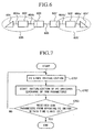
- control section 110 of the inter-network bridging apparatus 100 When the control section 110 receives an abnormal notification cell from the ATM network, processing step is transited to step S204 so as to start the FC link init-protocol (S201).
- the abnormal notification cell is an ATM cell, and can be transmitted by any opposing inter-network bridging apparatuses connecting the FC networks through the common ATM network, and is used to notify an abnormal event occurring in the ATM network or FC networks connected to the bridging apparatus 100.
- an abnormal notification cell is sent to the ATM network, and the process is transferred to step S204 so as to start the FC link init-protocol (S202, S203).
- ATM network abnormality includes, in addition to the abnormal events in transferring data through the ATM network, startup conditions of the bridging apparatus itself. If “abnormal event” occurs during startup in the inter-network bridging apparatus, the inter-network bridging apparatus detects the abnormal event occurring in the bridging apparatus itself in step S202, and skips the step of sending the abnormal notification cell (S203), and transfers the process to the step S204 to start the FC link init-protocol. In other words, if "abnormal event” is caused by the startup in the inter-network bridging apparatus, the inter-network bridging apparatus starts the FC link init-protocol by performing processing steps subsequent to step S204.
- the apparatus 100 first sends out an offline code (OLS), and waits for the arrival of an FC link reset code (LR) (S204, 205).
- OLS offline code
- LR FC link reset code
- the apparatus 100 starts sending an init-start cell to the ATM network every periodic interval (T) (S206).
- FC link init-protocol is stopped until an init-complete cell is received from the ATM network.
- init-start cells are continued to be repeatedly every periodic interval (T).
- T periodic interval
- the process is transferred to step S210 to re-start the FC link init-protocol (S207).
- an init-start cell is received from the ATM network while the FC link init-protocol is being suspended, an init-complete cell is sent to the ATM network (S208, S209).
- the FC link init-protocol is restarted by taking the first step to stop sending the init-start cells to the ATM network, which has been carried out at periodic intervals (T) (S210).
- T periodic intervals
- LR FC link reset code
- the process in a standby state until an FC link reset response code (LRR) is received from the FC link (S211, S212). If the FC reset response code (LRR) is received from the FC link, a special code (Idle) is sent to the FC link, and the process becomes idle until the status code (Idle) is received from the FC link.
- the status code (Idle) is received from the FC link, it indicates that the FC link init-protocol has been completed.
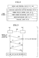
- Figure 3 shows the sequence of events which take place in the interval from abnormality generation to normality recovery, and 301 and 301' relate to the inter-network bridging apparatuses; 302, 302' to FC switches; 303, 303' to FC links; 304, 304' to FC networks; and 305 to the ATM network.
- the example of abnormal event described in the following relates to a situation in which an abnormal event is occurred in the data transfer line of the ATM network 305 directed from the inter-network bridging apparatus 301' to the inter-network bridging apparatus 301, while the transfer line directing the data from apparatus 301 to apparatus 301' is normal.
- the FC link init-protocols for FC links 303, 303' are the same as those described above, so that the same reference numerals are used for their explanation.
- Inter-network bridging apparatuses 301 and 301' monitor the operation of FC links 303, 303' according to the kind of the ordered set of codes received from the FC links 303, 303', and also monitor the operation of FC networks 304, 304' and ATM network 305 according to alarm signals received from the ATM network.
- the inter-network bridging apparatus 301 When the inter-network bridging apparatus 301 detects an abnormal event, it sends an abnormal notification cell to ATM network 305, and starts sending an offline code (OLS) to FC switch 302 to indicate that it is in the init-start state.
- OLS offline code
- FC switch 302 When the FC switch 302 receives the offline code (OLS), it detects that an abnormal event has taken place in the network so that the inter-network bridging apparatus 301 is in the init-start state. In response to this detection, FC switch 302 sends a link reset code (LR) to indicate starting of FC link initialization.
- OLS offline code
- LR link reset code
- the inter-network bridging apparatus 301 which receives the link reset code (LR), periodically sends an init-start cell to the ATM network 305 every interval (T), until an init-complete cell is received from the ATM network 305. Also, the inter-network bridging apparatus 301 withholds sending a link reset response code (LRR) as the response to the link reset code (LR). It should be noted here that, in the conventional method, a link reset response code (LRR) would have been sent to FC switch 302 at this point. Therefore, FC link init-protocol for FC link 302 is temporarily suspended in the present method.
- LRR link reset response code
- the inter-network bridging apparatus 301' receiving an abnormal notification cell from the ATM network 305 sends an offline code (OLS) to FC switch 302'.
- FC switch 302' receiving the offline code (OLS) sends a link reset code (LR) to the inter-network bridging apparatus 301', in response.
- Inter-network bridging apparatus 301' receiving the link reset code (LR) periodically sends an init-start cell to the ATM network 305 every interval (T) until an init-complete cell is received from the ATM network 305.
- the inter-network bridging apparatus 301' withholds sending a link reset response code (LRR), which would have been sent at the point to FC switch 302' in the conventional method, until an init-complete cell is received from the ATM network 305. Accordingly, the init-protocol of FC link 302' is suspended temporary at this point. The init-start cell sent by the inter-network bridging apparatus 301' is not received by the inter-network bridging apparatus 301 until the abnormality in the ATM network 305 is recovered.
- LRR link reset response code
- the inter-network bridging apparatus 301' Upon receiving the init-start cell from the ATM network 305, the inter-network bridging apparatus 301' checks whether it has already sent init-start cells, or not. If the inter-network bridging apparatus 301' had already sent init-start cells, the inter-network bridging apparatus 301' will send an init-complete cell to ATM network 305 when an init-start cell is received normally from the ATM network 305. If the inter-network bridging apparatus 301' has not sent any init-start cell, init-complete cell will not be sent.
- the inter-network bridging apparatus 301 will not be received by the inter-network bridging apparatus 301 until normality will been restored in the ATM network 305, therefore, the inter-network bridging apparatus 301 will not send an init-complete cell.
- the inter-network bridging apparatus 301 When the abnormality in the ATM network 305 is restored, the inter-network bridging apparatus 301 receives the init-start cell sent by the inter-network bridging apparatus 301', and in response, it sends an init-complete cell to the ATM network 305. Upon receiving the init-complete cell, the inter-network bridging apparatus 301' stops sending init-start cells which have been periodically sent every interval (T).
- Each of the inter-network bridging apparatuses 301 and 301' which received the init-complete cell send a link reset code (LR) to the FC switches 302 and 302' to notify the FC link to start initialization respectively, thereby the suspended initialization process of FC links 303 and 303' are restarted.
- FC switches 302 and 302' which received the link reset code (LR) send respective responses in the form of link reset response code (LRR).
- LRR link reset response code
- the inter-network bridging apparatuses 301 and 301' are now in a state ready to transfer data, and both apparatuses send a special code (Idle) to respective FC switches 302 and 302'.
- FC switches 302, 302' receiving the status code (Idle) are now in a state ready to transfer data, and each switch sends a special code (Idle) to the respective inter-network bridging apparatus 301 and 301'. At this point, initialization processes for both FC links 303, 303' are completed.
- abnormal event in the composite network will be illustrated by presenting a case of the inter-network bridging apparatus 301 being activated before the inter-network bridging apparatus 301' being activated.
- the difference in the processing sequence from those explained with reference to Figure 3 is that, if the abnormal event occurs during the startup in the inter-network bridging apparatuses 301 or 301', this event is detected in step S202 shown in Figure 2 that the abnormality is due to the startup in an inter-network bridging apparatus itself, and the process jumps to step S204 to start the FC link init-protocol, without sending an abnormal notification cell (S203).
- inter-network bridging apparatuses 301 and 301' both perform FC init-protocol steps following step S204. Other steps are the same as those described above.
- "normality recovery" in Figure 3 relates to startup phase of the inter-network bridging apparatus 301'.
- the present inter-network bridging apparatus upon detecting an ATM abnormality or an FC link abnormality, is able to notify FC switches and inter-network bridging apparatuses of the opposite networks connected through a common ATM network of the abnormality. Therefore, when normality is recovered in the composite network, FC link initialization can be carried out reliably and quickly with such the notifications. Also, initialization processes can be carried out in connect plural FC networks connected to the ATM network at the nearly same time, thereby providing smooth initialization process of the FC/ATM composite network.
- FC links can be initialized at the nearly time, so that the initialization process for the composite network can proceed smoothly.
- sequence of processing steps need not be limited to those demonstrated, and other init-protocol sequences are equally applicable. It would be evident furthermore that although the example was based on conversion (mapping) between AAL frame and FC-2 frame, other approaches, such as conversion (mapping) between AAL frame and FC-1 frame, are equally applicable.
- FC networks and ATM network can be carried out by means of computer application programs contained in a computer readable recording medium to be operated by a computer system.
- Computer system includes any operating systems (OS) and peripheral hardwares that are connected (remotely or directly) to the FC networks and ATM network.
- Computer readable recording media includes portable media such as floppy disks, opto-magnetic disks, ROM, CD-ROM, as well as fixed devices such as hard disks housed in computer systems.
- Application program may perform a part of the described functions, or may be operated in conjunction with pre-recorded programs stored in computer systems.
- the present inter-network bridging apparatus can be used to connect connect plural FC networks to an ATM network to form an FC/ATM composite network, and when an abnormal event occurs in the composite network, FC networks adjoining the ATM network are notified of the abnormal event, and when normality is restored, the initializing protocol is started in each FC network almost simultaneously. Therefore, when the abnormality is eliminated from the composite network, it is possible to complete the initialization processes normally in the FC networks adjoining the ATM network so that communication between the FC networks can be restored quickly. Similarly, FC link initialization can be started almost simultaneously at the startup of the inter-network bridging apparatus, so that initialization process for the composite network can be carried out smoothly.
- the composite network is configured so that an initialization-start cell is sent periodically every constant intervals until an initialization-complete cell is received by the apparatus on the receiving-side so that the normality recovery and completion of initialization preparation can be performed reliably and quickly.
Landscapes
- Engineering & Computer Science (AREA)
- Computer Networks & Wireless Communication (AREA)
- Data Exchanges In Wide-Area Networks (AREA)
- Computer And Data Communications (AREA)
Claims (9)
- Verfahren zum Steuern der Kommunikation in einem kombinierten Netz, das mehrere Faserkanal-Netze (304, 304'), deren Faserkanalverbindungen (303, 303') durch Ausführen eines Initialisierungsprotokolls initialisiert werden, und ein Netz mit asynchroner Übertragungsbetriebsart, ein so genanntes ATM-Netz (305), das zu den Faserkanal-Netzen (304, 304') hinzugefügt ist, umfasst, wobei die Faserkanal-Netze und das ATM-Netz über entsprechende Zwischennetz-Brückenvorrichtungen (301, 301') miteinander verbunden sind, um Tasks auszuführen, umfassend die folgenden Schritte:Überwachen der Faserkanal-Netze und des ATM-Netzes (S202);Senden einer Anomalie-melden-Zelle zu dem ATM-Netz, wenn ein anomales Ereignis entweder in den Faserkanal-Netzen oder in dem ATM-Netz erfasst wird (S203);Starten eines Initialisierungsprotokolls der Faserkanalverbindung, wenn das anomale Ereignis erfasst wird oder wenn eine Anomalie-melden-Zelle von dem ATM-Netz empfangen wird (S204-S205);Senden einer Reihe von Initialisierung-starten-Zellen zu dem ATM-Netz und Anhalten des Initialisierungsprotokolls der Faserkanalverbindung, bis während der Ausführung des Initialisierungsprotokolls der Faserkanalverbindung eine Initialisierung-vollständig-Zelle von dem ATM-Netz empfangen wird (S206-S207);Senden einer Initialisierung-vollständig-Zelle zu dem ATM-Netz, wenn eine Initialisierung-starten-Zelle von dem ATM-Netz empfangen wird, nachdem die Initialisierung-starten-Zellen gesendet worden sind (S208-S209);Anhalten des Sendens der Initialisierung-starten-Zellen, die periodisch gesendet worden sind, wenn die Initialisierung-vollständig-Zelle von dem ATM-Netz empfangen wird (S21 0); underneutes Starten des Initialisierungsprotokolls in den Faserkanal-Schaltern, um die Wiederherstellung der Faserkanalverbindungen abzuschließen (S211-S214).
- Verfahren nach Anspruch 1, wobei das Verfahren einen Schritt des Sendens einer Anomalie-melden-Zelle zu dem ATM-Netz, wenn in den Faserkanal-Netzen oder in dem ATM-Netz ein anomales Ereignis mit Ausnahme eines anomalen Ereignisses, das durch das Hochfahren in der Zwischennetz-Brückenvorrichtung verursacht wird, erfasst wird, umfasst (S203).
- Verfahren nach einem der Ansprüche 1 oder 2, bei dem eine Initialisierung-starten-Zelle in periodischen Intervallen gesendet wird, bis eine Initialisierung-vollständig-Zelle empfangen wird (S206).
- Zwischennetz-Brückenvorrichtung (301 und 301') zum Überbrücken mehrerer Faserkanal-Netze (304, 304'), deren Faserkanalverbindungen (303, 303') durch Ausführen eines Initialisierungsprotokolls initialisiert werden, und eines Netzes für asynchrone Übertragungsbetriebsart, ein so genanntes ATM-Netz (305), wobei die Vorrichtung umfasst:eine Faserkanalverbindung-Überwachungseinrichtung (111) zum Überwachen und Erfassen eines anomalen Ereignisses in den Faserkanal-Netzen;eine ATM-Netz-Überwachungseinrichtung (112) zum Überwachen und Erfassen eines anomalen Ereignisses in dem ATM-Netz; undeine Steuereinrichtung (110) zum Ausführen der folgenden Schritte: Senden einer Anomalie-melden-Zelle zu dem ATM-Netz, wenn ein anomales Ereignis entweder in den Faserkanal-Netzen oder in dem ATM-Netz erfasst wird (S203); Starten des Initialisierungsprotokolls für die Faserkanalverbindung, wenn das anomale Ereignis erfasst wird oder wenn eine Anomalie-melden-Zelle von dem ATM-Netz empfangen wird (S204-S205); Senden einer Reihe von Initialisierung-starten-Zellen zu dem ATM-Netz und während der Ausführung des Initialisierungsprotokolls der Faserkanalverbindung Anhalten des Initialisierungsprotokolls für die Faserkanalverbindung, bis eine Initialisierung-vollständig-Zelle von dem ATM-Netz empfangen wird (S206-S207); Senden einer Initialisierung-vollständig-Zelle zu dem ATM-Netz, wenn eine Initialisierung-starten-Zelle von dem ATM-Netz empfangen wird, nachdem die Initialisierung-starten-Zellen gesendet worden sind (S208-S209); Anhalten des Sendens der Initialisierung-starten-Zellen, die periodisch gesendet worden sind, wenn die Initialisierung-vollständig-Zelle von dem ATM-Netz empfangen wird (S210); und erneutes Starten des Initialisierungsprotokolls in den Faserkanal-Schaltern, um die Wiederherstellung der Faserkanalverbindungen abzuschließen (S211-S214).
- Vorrichtung nach Anspruch 4, bei der die Steuereinrichtung (110) eine Anomalie-melden-Zelle zu dem ATM-Netz sendet, wenn ein anomales Ereignis in den Faserkanal-Netzen oder in dem ATM-Netz mit Ausnahme eines anomalen Ereignisses, das durch das Hochfahren in der Zwischennetz-Brückenvorrichtung verursacht wird, erfasst wird (S203).
- Vorrichtung nach einem der Ansprüche 4 oder 5, bei der die Steuereinrichtung (110) eine Initialisierung-starten-Zelle in periodischen Intervallen sendet, bis eine Initialisierung-vollständig-Zelle empfangen wird (S206).
- Computerprogrammprodukt, das ein computerlesbares Programm enthält, das auf ein von einem Computer verwendbares Medium aufgezeichnet ist, um einen Computer dazu zu veranlassen, eine Faserkanalverbindung durch Ausführen eines Initialisierungsprotokolls zu initialisieren, wobei das Computerprogramm die folgenden Schritte ausführt:Überwachen der Faserkanal-Netze und des ATM-Netzes (S202);Senden einer Anomalie-melden-Zelle zu dem ATM-Netz, wenn ein anomales Ereignis entweder in den Faserkanal-Netzen oder in dem ATM-Netz erfasst wird (S203);Starten eines Initialisierungsprotokolls der Faserkanalverbindungen, wenn das anomale Ereignis erfasst wird oder wenn eine Anomalie-melden-Zelle von dem ATM-Netz empfangen wird (S204-S205);Senden einer Reihe von Initialisierung-starten-Zellen zu dem ATM-Netz und Anhalten des Initialisierungsprotokolls der Faserkanalverbindungen, bis während der Ausführung des Initialisierungsprotokolls der Faserkanalverbindungen eine Initialisierung-vollständig-Zelle von dem ATM-Netz empfangen wird (S206-S207);Senden einer Initialisierung-vollständig-Zelle zu dem ATM-Netz, wenn eine Initialisierung-starten-Zelle von dem ATM-Netz empfangen wird, nachdem Initialisierung-starten-Zellen gesendet worden sind (S208-S209);Anhalten des Sendens der Initialisierung-starten-Zellen, die periodisch gesendet worden sind, wenn die Initialisierung-vollständig-Zelle von dem ATM-Netz empfangen wird (S210); underneutes Starten des Initialisierungsprotokolls in den Faserkanal-Schaltern, um die Wiederherstellung der Faserkanalverbindungen abzuschließen (S211-S214).
- Computerprogrammprodukt nach Anspruch 7, wobei das Computerprogramm einen Schritt des Sendens einer Anomalie-melden-Zelle zu dem ATM-Netz ausführt, wenn ein anomales Ereignis in den Faserkanal-Netzen oder in dem ATM-Netz mit Ausnahme eines anomalen Ereignisses, das durch das Hochfahren in der Zwischennetz-Brückenvorrichtung verursacht wird, erfasst wird (S203).
- Aufzeichnungsmedium nach einem der Ansprüche 7 oder 8, bei dem eine Initialisierung-starten-Zelle in periodischen Intervallen gesendet wird, bis eine Initialisierung-vollständig-Zelle empfangen wird (S206).
Applications Claiming Priority (2)
| Application Number | Priority Date | Filing Date | Title |
|---|---|---|---|
| JP3891698A JP3224521B2 (ja) | 1998-02-20 | 1998-02-20 | Fc/atm複合ネットワークの通信制御方法及びネットワーク間接続装置 |
| JP3891698 | 1998-02-20 |
Publications (3)
| Publication Number | Publication Date |
|---|---|
| EP0938246A2 EP0938246A2 (de) | 1999-08-25 |
| EP0938246A3 EP0938246A3 (de) | 2004-07-28 |
| EP0938246B1 true EP0938246B1 (de) | 2005-12-21 |
Family
ID=12538543
Family Applications (1)
| Application Number | Title | Priority Date | Filing Date |
|---|---|---|---|
| EP19990400377 Expired - Lifetime EP0938246B1 (de) | 1998-02-20 | 1999-02-17 | Verfahren und Anordnung zur Verbindung von Fibre-Channel-Netzen und ATM-Netzen |
Country Status (4)
| Country | Link |
|---|---|
| US (1) | US6014370A (de) |
| EP (1) | EP0938246B1 (de) |
| JP (1) | JP3224521B2 (de) |
| DE (1) | DE69928977T2 (de) |
Families Citing this family (5)
| Publication number | Priority date | Publication date | Assignee | Title |
|---|---|---|---|---|
| US6401128B1 (en) * | 1998-08-07 | 2002-06-04 | Brocade Communiations Systems, Inc. | System and method for sending and receiving frames between a public device and a private device |
| US6400730B1 (en) * | 1999-03-10 | 2002-06-04 | Nishan Systems, Inc. | Method and apparatus for transferring data between IP network devices and SCSI and fibre channel devices over an IP network |
| US7114009B2 (en) * | 2001-03-16 | 2006-09-26 | San Valley Systems | Encapsulating Fibre Channel signals for transmission over non-Fibre Channel networks |
| US7047346B2 (en) * | 2001-12-31 | 2006-05-16 | Storage Technology Corporation | Transparent fiber channel concentrator for point to point technologies |
| US7568026B2 (en) * | 2004-02-13 | 2009-07-28 | Cisco Technology, Inc. | Method and system for efficient link recovery for fibre channel over SONET/SDH transport path |
Family Cites Families (6)
| Publication number | Priority date | Publication date | Assignee | Title |
|---|---|---|---|---|
| JP2660422B2 (ja) * | 1988-05-31 | 1997-10-08 | 株式会社日立製作所 | 動作モード設定可能なlan間結合装置 |
| JPH04165846A (ja) * | 1990-10-30 | 1992-06-11 | Fujitsu Ltd | 対局アラーム転送方法 |
| US5291491A (en) * | 1991-01-22 | 1994-03-01 | Digital Equipment Corporation | Avoidance of false re-initialization of a computer network |
| CA2107299C (en) * | 1993-09-29 | 1997-02-25 | Mehrad Yasrebi | High performance machine for switched communications in a heterogenous data processing network gateway |
| JP3386215B2 (ja) * | 1994-02-10 | 2003-03-17 | 富士通株式会社 | Atm通信システムにおけるais伝送方式、送信側atm装置、及びatm通信システム |
| EP0697801A2 (de) * | 1994-08-15 | 1996-02-21 | Hewlett-Packard Company | Fibre-Channel auf ATM |
-
1998
- 1998-02-20 JP JP3891698A patent/JP3224521B2/ja not_active Expired - Lifetime
-
1999
- 1999-02-17 DE DE1999628977 patent/DE69928977T2/de not_active Expired - Fee Related
- 1999-02-17 EP EP19990400377 patent/EP0938246B1/de not_active Expired - Lifetime
- 1999-02-18 US US09/252,033 patent/US6014370A/en not_active Expired - Fee Related
Also Published As
| Publication number | Publication date |
|---|---|
| EP0938246A2 (de) | 1999-08-25 |
| DE69928977D1 (de) | 2006-01-26 |
| EP0938246A3 (de) | 2004-07-28 |
| DE69928977T2 (de) | 2006-08-31 |
| JPH11239143A (ja) | 1999-08-31 |
| JP3224521B2 (ja) | 2001-10-29 |
| US6014370A (en) | 2000-01-11 |
Similar Documents
| Publication | Publication Date | Title |
|---|---|---|
| AU633676B2 (en) | Station-to-station full duplex communication in a token ring area network | |
| JP3777008B2 (ja) | 障害復旧制御方法 | |
| JPH10135964A (ja) | ネットワークシステム及びフレームリレー交換機 | |
| CA2261323A1 (en) | Backup procedure for dss2-based signalling links | |
| EP0938246B1 (de) | Verfahren und Anordnung zur Verbindung von Fibre-Channel-Netzen und ATM-Netzen | |
| JP3837696B2 (ja) | 伝送装置及びデータ伝送方法 | |
| JPH04238557A (ja) | リンクレベル・ファシリティ | |
| WO1999043184A1 (en) | Protection switching of virtual connections | |
| JP2003298625A (ja) | リング型の非同期転送モード転送システムでの保護切替方法 | |
| JP2011049958A (ja) | 通信端末、通信システムおよびノード切り替え方法 | |
| JP2001237889A (ja) | データ通信網における迂回経路制御方法及び装置 | |
| JP3938037B2 (ja) | 二重リング型ネットワーク | |
| EP1026918B1 (de) | Sicherstellungsverfahren für Signalisierungsverbindungen | |
| JPH03169139A (ja) | ネツトワーク構成制御方式 | |
| JP3301590B2 (ja) | プロトコル状態同期化システム | |
| CN118921318B (zh) | 一种基于5glan的报文双发选收方法 | |
| JP2002252632A (ja) | Atm伝送装置、及びその冗長伝送系の切替方法 | |
| JP7622325B2 (ja) | ネットワークスイッチ及びそのデュアルホーミングのリンク回復方法 | |
| JP2012129864A (ja) | 通信システム及びユーザアクセス装置を制御する方法 | |
| JP4612289B2 (ja) | 冗長構成制御方法およびブリッジ装置 | |
| JPH07107108A (ja) | Lan用故障点切離し装置 | |
| JP2000174759A (ja) | ループバックセルによるセルの疎通判定方法および処理方法 | |
| JP3072731B2 (ja) | 予備系定周期監視によるvp切替方法及びシステム | |
| JP2000078159A (ja) | Vp切替装置及びそれに用いるコネクション監視方法並びにその制御プログラムを記録した記録媒体 | |
| JPH0496447A (ja) | バーチャルパス切り替え装置 |
Legal Events
| Date | Code | Title | Description |
|---|---|---|---|
| PUAI | Public reference made under article 153(3) epc to a published international application that has entered the european phase |
Free format text: ORIGINAL CODE: 0009012 |
|
| AK | Designated contracting states |
Kind code of ref document: A2 Designated state(s): AT BE CH CY DE DK ES FI FR GB GR IE IT LI LU MC NL PT SE |
|
| AX | Request for extension of the european patent |
Free format text: AL;LT;LV;MK;RO;SI |
|
| PUAL | Search report despatched |
Free format text: ORIGINAL CODE: 0009013 |
|
| AK | Designated contracting states |
Kind code of ref document: A3 Designated state(s): AT BE CH CY DE DK ES FI FR GB GR IE IT LI LU MC NL PT SE |
|
| AX | Request for extension of the european patent |
Extension state: AL LT LV MK RO SI |
|
| RIC1 | Information provided on ipc code assigned before grant |
Ipc: 7H 04L 12/46 B Ipc: 7H 04L 12/56 B Ipc: 7H 04Q 11/04 A |
|
| 17P | Request for examination filed |
Effective date: 20041022 |
|
| 17Q | First examination report despatched |
Effective date: 20041203 |
|
| AKX | Designation fees paid |
Designated state(s): DE FR GB |
|
| GRAP | Despatch of communication of intention to grant a patent |
Free format text: ORIGINAL CODE: EPIDOSNIGR1 |
|
| RTI1 | Title (correction) |
Free format text: APPARATUS FOR BRIDGING BETWEEN FIBRE CHANNEL NETWORKS AND ATM NETWORKS |
|
| GRAS | Grant fee paid |
Free format text: ORIGINAL CODE: EPIDOSNIGR3 |
|
| GRAA | (expected) grant |
Free format text: ORIGINAL CODE: 0009210 |
|
| AK | Designated contracting states |
Kind code of ref document: B1 Designated state(s): DE FR GB |
|
| REG | Reference to a national code |
Ref country code: GB Ref legal event code: FG4D |
|
| REF | Corresponds to: |
Ref document number: 69928977 Country of ref document: DE Date of ref document: 20060126 Kind code of ref document: P |
|
| ET | Fr: translation filed | ||
| PLBE | No opposition filed within time limit |
Free format text: ORIGINAL CODE: 0009261 |
|
| STAA | Information on the status of an ep patent application or granted ep patent |
Free format text: STATUS: NO OPPOSITION FILED WITHIN TIME LIMIT |
|
| 26N | No opposition filed |
Effective date: 20060922 |
|
| PGFP | Annual fee paid to national office [announced via postgrant information from national office to epo] |
Ref country code: DE Payment date: 20090213 Year of fee payment: 11 |
|
| PGFP | Annual fee paid to national office [announced via postgrant information from national office to epo] |
Ref country code: GB Payment date: 20090211 Year of fee payment: 11 |
|
| PGFP | Annual fee paid to national office [announced via postgrant information from national office to epo] |
Ref country code: FR Payment date: 20090213 Year of fee payment: 11 |
|
| GBPC | Gb: european patent ceased through non-payment of renewal fee |
Effective date: 20100217 |
|
| REG | Reference to a national code |
Ref country code: FR Ref legal event code: ST Effective date: 20101029 |
|
| PG25 | Lapsed in a contracting state [announced via postgrant information from national office to epo] |
Ref country code: FR Free format text: LAPSE BECAUSE OF NON-PAYMENT OF DUE FEES Effective date: 20100301 |
|
| PG25 | Lapsed in a contracting state [announced via postgrant information from national office to epo] |
Ref country code: DE Free format text: LAPSE BECAUSE OF NON-PAYMENT OF DUE FEES Effective date: 20100901 |
|
| PG25 | Lapsed in a contracting state [announced via postgrant information from national office to epo] |
Ref country code: GB Free format text: LAPSE BECAUSE OF NON-PAYMENT OF DUE FEES Effective date: 20100217 |