EP0937874A2 - System zum Starten einer Gasturbine - Google Patents
System zum Starten einer Gasturbine Download PDFInfo
- Publication number
- EP0937874A2 EP0937874A2 EP99102725A EP99102725A EP0937874A2 EP 0937874 A2 EP0937874 A2 EP 0937874A2 EP 99102725 A EP99102725 A EP 99102725A EP 99102725 A EP99102725 A EP 99102725A EP 0937874 A2 EP0937874 A2 EP 0937874A2
- Authority
- EP
- European Patent Office
- Prior art keywords
- turbine
- steam
- starting
- gas
- compressor
- Prior art date
- Legal status (The legal status is an assumption and is not a legal conclusion. Google has not performed a legal analysis and makes no representation as to the accuracy of the status listed.)
- Withdrawn
Links
- 238000001514 detection method Methods 0.000 claims abstract description 6
- 239000007789 gas Substances 0.000 claims description 75
- 239000000567 combustion gas Substances 0.000 claims description 9
- 238000002485 combustion reaction Methods 0.000 claims description 3
- 239000000446 fuel Substances 0.000 claims description 3
- 230000000630 rising effect Effects 0.000 abstract description 2
- 238000010586 diagram Methods 0.000 description 3
- 238000000605 extraction Methods 0.000 description 2
- 238000001816 cooling Methods 0.000 description 1
- 230000004048 modification Effects 0.000 description 1
- 238000012986 modification Methods 0.000 description 1
- 238000005549 size reduction Methods 0.000 description 1
Images


Classifications
-
- F—MECHANICAL ENGINEERING; LIGHTING; HEATING; WEAPONS; BLASTING
- F02—COMBUSTION ENGINES; HOT-GAS OR COMBUSTION-PRODUCT ENGINE PLANTS
- F02C—GAS-TURBINE PLANTS; AIR INTAKES FOR JET-PROPULSION PLANTS; CONTROLLING FUEL SUPPLY IN AIR-BREATHING JET-PROPULSION PLANTS
- F02C7/00—Features, components parts, details or accessories, not provided for in, or of interest apart form groups F02C1/00 - F02C6/00; Air intakes for jet-propulsion plants
- F02C7/26—Starting; Ignition
- F02C7/268—Starting drives for the rotor, acting directly on the rotor of the gas turbine to be started
Definitions
- the present invention relates to a gas turbine, and in particular, to a gas turbine starting control system capable of increasing starting power while suppressing an rise in inlet gas temperature of the turbine during starting of the gas turbine.
- Fig. 3 is a block diagram schematically showing a general gas turbine.
- reference numeral 1 indicates a compressor for compressing intake gas (air) 2
- reference numeral 5 indicates a turbine coaxially provided with the compressor 1
- reference numeral 4 indicates a combustor.
- High-pressure air compressed by the compressor 1 is first delivered through a compressed-air path 13 to the combustor 4 where fuel is injected into the high-pressure air for combustion.
- combustion gas is generated.
- This combustion gas is then delivered to the turbine 5 through a combustion gas path 12 to perform expansion work by acting on moving blades of the turbine.
- the gas turbine with the above mentioned arrangement generally exhausts some of the intake gas 2 (air) sucked into the compressor 1 to the outside through an extraction pipe 3 during starting of the gas turbine to prevent a rotating stall of the compressor 1. Accordingly, since the gas supplied to the turbine 5 through the combustor 4 has a smaller flow rate during starting of the gas turbine, there is a need for auxiliary power to start rotation of the rotational shaft of the compressor 1 and turbine 5. Consequently, a starting motor 6 is connected to the rotational shaft of the compressor 1 and turbine 5, and the power of the starting motor 6 is supplied thereto as an auxiliary power for starting the gas turbine.
- Fig. 2 illustrates changes in an inlet gas temperature of the turbine with respect to the number of revolutions during starting of the above mentioned gas turbine provided with a starting motor.
- the inlet gas temperature of the turbine reaches it's maximum point at about 50% of rated speed and may exceed a predetermined allowable value.
- line A in Fig. 2 indicates changes in the inlet gas temperature of the turbine with respect to the number of revolutions during starting of a gas turbine in accordance with the present invention, to be described later.
- the present invention has been made to provide a gas turbine starting control system, wherein the starting power is enhanced while the inlet gas temperature of the turbine is restrained from rising during starting of the gas turbine, so that the starting motor can be reduced in size and the system costs can be reduced.
- the present invention is intended to solve the foregoing problems and the gist of the present invention is to provide a gas turbine starting control system for a gas turbine in which starting power is supplied to a rotational shaft of a compressor and turbine by using a starting motor in order to start the compressor and the turbine is characterized by comprising: a steam pipe for supplying steam to a combustor in the gas turbine; a temperature detector for detecting an inlet gas temperature of the turbine; a steam control valve provided at the steam pipe for opening and closing the steam pipe; and a valve controlling unit for controlling the opening degree of the steam control valve in response to detection signals of the inlet gas temperature from the temperature detector.
- the valve controlling unit outputs a release signal to the steam control valve when the inlet gas temperature detected by the temperature detector is above a predetermined allowable value.
- the steam control valve then opens the steam pipe leading to the combustor in response to the release signals.
- steam having a predetermined pressure is delivered to the combustor and then supplied to the turbine together with the gas delivered from the combustor.
- the turbine can obtain an output increase corresponding to the energy of the steam delivered to the combustor during starting while the inlet gas temperature of the turbine can be kept at a predetermined allowable value or lower. Therefore, according to the present invention, the inlet gas temperature of the turbine can be maintained at a predetermined allowable value or lower, and the gas turbine can be safely started up with a large starting power supplemented by the energy of the steam.
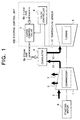
- Fig. 1 is a block diagram showing a gas turbine starting control system in accordance with the present invention
- Fig. 2 is a graph showing turbine inlet gas temperature.
- reference numeral 1 indicates a compressor for compressing intake gas (air) 2
- reference numeral 5 indicates a turbine coaxially provided with the compressor 1
- reference numeral 4 indicates a combustor.
- High-pressure air compressed by the compressor 1 is first delivered through a compressed-air path 13 to the combustor 4, where fuel is injected into the high-pressure air for combustion. As a result, a combustion gas is generated.
- This combustion gas is then delivered to the turbine 5 through a combustion gas path 12 to perform expansion work by acting on the moving blades of the turbine.
- Reference numeral 3 denotes an extraction pipe for extracting some of the intake gas 2 outside of the compressor 1 so as to prevent rotating stall in the compressor 1 during starting of the gas turbine.
- Reference numeral 6 denotes a starting motor directly connected to the rotational shaft of the compressor 1 for supplying rotational power to the compressor 1 and to the turbine 5 during starting. The foregoing arrangement is made in the same manner as in the conventional one shown in Fig. 3.
- Reference numeral 100 indicates a starting control system in accordance with the present invention, and is comprised of a steam control valve 7 and a valve controlling unit 9 Steam having a predetermined pressure is introduced into the steam control valve 7 from a steam source (not shown) through a steam pipe 8b. On the other hand, an outlet of the steam control valve 7 is connected to the combustor 4 via a steam pipe 8a.
- Reference numeral 11 indicates a temperature sensor for detecting the inlet gas temperature of the gas turbine 5. Detection signals of the inlet gas temperature detected by the temperature sensor 11 are input to the valve controlling unit 9. Output signals of the valve controlling unit 9, i.e., valve controlling signals, are then transmitted to the steam control valve 7.
- the steam control valve 7 has an arrangement such that the valve opening degree thereof can be controlled by the valve controlling signals in the valve controlling unit 9.
- a gas turbine provided with the starting control system having the above mentioned arrangement will now be described in terms of the operations thereof during starting of the gas turbine.
- the starting motor 6 is driven, and the compressor 1 and the turbine 5 are subjected to rotation during starting of the gas turbine, the output of the gas turbine is increased and the turbine inlet gas temperature is also increased.
- the temperature sensor 11 detects this inlet gas temperature to allow the detection signals to be input to the valve controlling unit 9.
- the allowable value of the inlet gas temperature of the turbine is preset in the valve controlling unit 9. Therefore, when the inlet gas temperature detected by the temperature sensor 11 reaches the predetermined allowable value or above, the valve controlling unit 9 outputs a valve release signal to the steam control valve 7.
- the steam control valve 7 Upon receiving the valve release signals, the steam control valve 7 is released, and the steam pipes 8a, 8b are communicated with each other.
- This allows the steam having the predetermined pressure to be delivered to the combustor 4.
- the thus delivered steam is supplied to the turbine 5 together with the combustion gas delivered from the combustor 4 to act on the turbine.
- the turbine 5 can therefore obtain an output increase corresponding to the energy of the steam delivered thereto during starting of the gas turbine. Further, this steam does not cause the inlet gas temperature of the turbine to increase, and hence the inlet gas temperature of the turbine is still maintained at the above mentioned allowable inlet gas temperature or lower.
- a gas turbine is generally designed so that the inlet gas temperature of the turbine during starting reaches the maximum point at about 50% of the rated speed thereof.
- the gas turbine provided with the starting control system according to the present invention is designed such that at about 50% of the rated speed, the valve controlling unit 9 opens the steam control valve 7 in response to the detection signal of the inlet gas temperature of the turbine to supply the steam.
- the inlet gas temperature of the turbine is maintained at the allowable value or lower, which is lower than that of the conventional turbine as indicated by line B.
- the opening degree of the steam control valve provided at the steam pipe is controlled during starting of the gas turbine. Consequently, the starting energy can be increased corresponding to the energy of the steam supplied to the combustor through the steam pipe while maintaining the inlet gas temperature of the turbine at a predetermined allowable value.
- the inlet gas temperature of the turbine can be maintained at a predetermined allowable value or lower.
- This enables the gas turbine to be safely started up with a larger starting energy to which the corresponding energy of the steam is added. Consequently, the starting motor can be reduced in size, thereby realizing the size reduction of the plant itself as well as a reduction of the system cost.
Landscapes
- Engineering & Computer Science (AREA)
- Chemical & Material Sciences (AREA)
- Combustion & Propulsion (AREA)
- Mechanical Engineering (AREA)
- General Engineering & Computer Science (AREA)
- Control Of Turbines (AREA)
- Engine Equipment That Uses Special Cycles (AREA)
Applications Claiming Priority (2)
| Application Number | Priority Date | Filing Date | Title |
|---|---|---|---|
| JP10037278A JPH11229898A (ja) | 1998-02-19 | 1998-02-19 | ガスタービンの起動制御装置 |
| JP3727898 | 1998-02-19 |
Publications (2)
| Publication Number | Publication Date |
|---|---|
| EP0937874A2 true EP0937874A2 (de) | 1999-08-25 |
| EP0937874A3 EP0937874A3 (de) | 2001-11-28 |
Family
ID=12493232
Family Applications (1)
| Application Number | Title | Priority Date | Filing Date |
|---|---|---|---|
| EP99102725A Withdrawn EP0937874A3 (de) | 1998-02-19 | 1999-02-19 | System zum Starten einer Gasturbine |
Country Status (4)
| Country | Link |
|---|---|
| US (1) | US6321526B1 (de) |
| EP (1) | EP0937874A3 (de) |
| JP (1) | JPH11229898A (de) |
| CA (1) | CA2262233C (de) |
Cited By (2)
| Publication number | Priority date | Publication date | Assignee | Title |
|---|---|---|---|---|
| WO2011008576A3 (en) * | 2009-07-15 | 2013-09-26 | Siemens Aktiengesellschaft | Method for removal of entrained gas in a combined cycle power generation system |
| CN111878239A (zh) * | 2020-08-06 | 2020-11-03 | 中国人民解放军海军工程大学 | 一种燃气轮机起动控制系统及方法 |
Families Citing this family (10)
| Publication number | Priority date | Publication date | Assignee | Title |
|---|---|---|---|---|
| GB2374904A (en) * | 2001-04-26 | 2002-10-30 | Bowman Power Systems Ltd | Controlling temperature in gas turbine apparatus during startup or shutdown |
| US20050056724A1 (en) * | 2003-09-11 | 2005-03-17 | Safe Flight Instrument Corporation | Helicopter turbine engine protection system |
| US7262712B2 (en) * | 2004-04-12 | 2007-08-28 | Safe Flight Instrument Corporation | Helicopter tactile exceedance warning system |
| CH697636B1 (de) * | 2005-04-18 | 2008-12-31 | Alstom Technology Ltd | Turbogruppe mit Anfahrvorrichtung. |
| EP1752619A2 (de) * | 2005-04-18 | 2007-02-14 | ALSTOM Technology Ltd | Turbogruppe mit Anfahrvorrichtung |
| GB2448116B (en) * | 2007-04-05 | 2009-05-27 | Rolls Royce Plc | Means for cooling a bearing assembly |
| US8833085B2 (en) * | 2010-01-27 | 2014-09-16 | General Electric Company | System and method for gas turbine startup control |
| US8997452B2 (en) * | 2011-10-20 | 2015-04-07 | General Electric Company | Systems and methods for regulating fuel and reactive fluid supply in turbine engines |
| US9611752B2 (en) | 2013-03-15 | 2017-04-04 | General Electric Company | Compressor start bleed system for a turbine system and method of controlling a compressor start bleed system |
| US12480423B2 (en) * | 2020-12-18 | 2025-11-25 | General Electric Company | System and method for mitigating bowed rotor in a gas turbine engine |
Family Cites Families (6)
| Publication number | Priority date | Publication date | Assignee | Title |
|---|---|---|---|---|
| US4350008A (en) * | 1979-12-26 | 1982-09-21 | United Technologies Corporation | Method of starting turbine engines |
| JPH0650068B2 (ja) * | 1988-12-09 | 1994-06-29 | 株式会社日立製作所 | ガスタービンの起動方法 |
| US5101619A (en) * | 1990-02-20 | 1992-04-07 | United Technologies Corporation | Method for correcting a hot start condition |
| SE9001688D0 (sv) * | 1990-05-10 | 1990-05-10 | Abb Stal Ab | Saett och anordning foer temperaturreglering i foerbraenningsanlaeggning |
| US5241817A (en) * | 1991-04-09 | 1993-09-07 | George Jr Leslie C | Screw engine with regenerative braking |
| JP3673020B2 (ja) | 1996-06-26 | 2005-07-20 | 株式会社東芝 | ガスタービン発電プラントの制御装置 |
-
1998
- 1998-02-19 JP JP10037278A patent/JPH11229898A/ja not_active Withdrawn
-
1999
- 1999-02-18 US US09/252,454 patent/US6321526B1/en not_active Expired - Fee Related
- 1999-02-18 CA CA002262233A patent/CA2262233C/en not_active Expired - Fee Related
- 1999-02-19 EP EP99102725A patent/EP0937874A3/de not_active Withdrawn
Non-Patent Citations (1)
| Title |
|---|
| None |
Cited By (3)
| Publication number | Priority date | Publication date | Assignee | Title |
|---|---|---|---|---|
| WO2011008576A3 (en) * | 2009-07-15 | 2013-09-26 | Siemens Aktiengesellschaft | Method for removal of entrained gas in a combined cycle power generation system |
| CN111878239A (zh) * | 2020-08-06 | 2020-11-03 | 中国人民解放军海军工程大学 | 一种燃气轮机起动控制系统及方法 |
| CN111878239B (zh) * | 2020-08-06 | 2021-06-22 | 中国人民解放军海军工程大学 | 一种燃气轮机起动控制系统及方法 |
Also Published As
| Publication number | Publication date |
|---|---|
| CA2262233A1 (en) | 1999-08-19 |
| CA2262233C (en) | 2002-08-27 |
| JPH11229898A (ja) | 1999-08-24 |
| US6321526B1 (en) | 2001-11-27 |
| EP0937874A3 (de) | 2001-11-28 |
Similar Documents
| Publication | Publication Date | Title |
|---|---|---|
| US6226974B1 (en) | Method of operation of industrial gas turbine for optimal performance | |
| EP0083109B1 (de) | Kombinierte Anlage mit Dampf- und Gasturbine, gekoppelt durch eine gemeinsame Welle | |
| US4793132A (en) | Apparatus for cooling steam turbine for use in single-shaft combined plant | |
| US6321526B1 (en) | Gas turbine starting control system | |
| US7472542B2 (en) | Gas-turbine power generating installation and method of operating the same | |
| US3971210A (en) | Start-up compressed air system for gas turbine engines | |
| US6145317A (en) | Steam turbine, steam turbine plant and method for cooling a steam turbine | |
| CN112334635B (zh) | 蒸汽涡轮机设备及其冷却方法 | |
| EP1329382B1 (de) | In eine Turbinenmaschine eingebautes Hilfstriebwerk | |
| US6786033B2 (en) | Methods and apparatus for operating gas turbine engines | |
| JP4163131B2 (ja) | 二軸式ガスタービン発電システム及びその停止方法 | |
| KR101243891B1 (ko) | 진공 배기 시스템 | |
| JPS63265798A (ja) | 船舶用の多重エンジン設備 | |
| JP3703872B2 (ja) | ガスタービン | |
| JP2908884B2 (ja) | 加圧流動床コンバインドプラントとその部分負荷運転制御方法及びその制御装置 | |
| JP2885346B2 (ja) | コンバインドプラントの制御方法及び同装置 | |
| JPH05171957A (ja) | ガスタービンの制御装置 | |
| JP3019678B2 (ja) | 抽気混圧蒸気タービン | |
| KR20040096502A (ko) | 제어시스템을 가진 압축기유니트 | |
| JP3699735B2 (ja) | ガスタービン設備の制御装置 | |
| JPH10121910A (ja) | 補機駆動用蒸気タービン設備 | |
| JP2000161083A (ja) | ガスタービン用燃料圧縮機システム | |
| EP2143892A1 (de) | Steuergerät für dampfturbinenbetrieb | |
| JPS6275028A (ja) | ガスタ−ビン装置の制御方法 | |
| JPH0711975A (ja) | ガスタービン装置 |
Legal Events
| Date | Code | Title | Description |
|---|---|---|---|
| PUAI | Public reference made under article 153(3) epc to a published international application that has entered the european phase |
Free format text: ORIGINAL CODE: 0009012 |
|
| AK | Designated contracting states |
Kind code of ref document: A2 Designated state(s): AT BE CH CY DE DK ES FI FR GB GR IE IT LI LU MC NL PT SE Kind code of ref document: A2 Designated state(s): CH DE FR GB IT LI |
|
| AX | Request for extension of the european patent |
Free format text: AL;LT;LV;MK;RO;SI |
|
| PUAL | Search report despatched |
Free format text: ORIGINAL CODE: 0009013 |
|
| AK | Designated contracting states |
Kind code of ref document: A3 Designated state(s): AT BE CH CY DE DK ES FI FR GB GR IE IT LI LU MC NL PT SE |
|
| AX | Request for extension of the european patent |
Free format text: AL;LT;LV;MK;RO;SI |
|
| RIC1 | Information provided on ipc code assigned before grant |
Free format text: 7F 02C 7/26 A, 7F 02C 7/27 B, 7F 02C 3/30 B |
|
| 17P | Request for examination filed |
Effective date: 20020109 |
|
| AKX | Designation fees paid |
Free format text: CH DE FR GB IT LI |
|
| 17Q | First examination report despatched |
Effective date: 20040922 |
|
| STAA | Information on the status of an ep patent application or granted ep patent |
Free format text: STATUS: THE APPLICATION IS DEEMED TO BE WITHDRAWN |
|
| 18D | Application deemed to be withdrawn |
Effective date: 20050824 |