EP0937852B1 - Betätigungsvorrichtung für Tür- oder Fensterkonstruktionen mit schwenkbaren Flügelelementen - Google Patents
Betätigungsvorrichtung für Tür- oder Fensterkonstruktionen mit schwenkbaren Flügelelementen Download PDFInfo
- Publication number
- EP0937852B1 EP0937852B1 EP99102003A EP99102003A EP0937852B1 EP 0937852 B1 EP0937852 B1 EP 0937852B1 EP 99102003 A EP99102003 A EP 99102003A EP 99102003 A EP99102003 A EP 99102003A EP 0937852 B1 EP0937852 B1 EP 0937852B1
- Authority
- EP
- European Patent Office
- Prior art keywords
- rocker arm
- hinged
- box element
- support structure
- move along
- Prior art date
- Legal status (The legal status is an assumption and is not a legal conclusion. Google has not performed a legal analysis and makes no representation as to the accuracy of the status listed.)
- Expired - Lifetime
Links
- 239000003638 chemical reducing agent Substances 0.000 claims 1
- 208000003443 Unconsciousness Diseases 0.000 description 2
- 238000006073 displacement reaction Methods 0.000 description 2
- 238000010276 construction Methods 0.000 description 1
- 230000008878 coupling Effects 0.000 description 1
- 238000010168 coupling process Methods 0.000 description 1
- 238000005859 coupling reaction Methods 0.000 description 1
- 239000002184 metal Substances 0.000 description 1
- 238000000034 method Methods 0.000 description 1
- 239000007787 solid Substances 0.000 description 1
Images


Classifications
-
- E—FIXED CONSTRUCTIONS
- E05—LOCKS; KEYS; WINDOW OR DOOR FITTINGS; SAFES
- E05D—HINGES OR SUSPENSION DEVICES FOR DOORS, WINDOWS OR WINGS
- E05D15/00—Suspension arrangements for wings
- E05D15/26—Suspension arrangements for wings for folding wings
- E05D15/264—Suspension arrangements for wings for folding wings for bi-fold wings
-
- E—FIXED CONSTRUCTIONS
- E05—LOCKS; KEYS; WINDOW OR DOOR FITTINGS; SAFES
- E05D—HINGES OR SUSPENSION DEVICES FOR DOORS, WINDOWS OR WINGS
- E05D3/00—Hinges with pins
- E05D3/06—Hinges with pins with two or more pins
- E05D3/18—Hinges with pins with two or more pins with sliding pins or guides
- E05D3/186—Scissors hinges, with two crossing levers and five parallel pins
-
- E—FIXED CONSTRUCTIONS
- E05—LOCKS; KEYS; WINDOW OR DOOR FITTINGS; SAFES
- E05F—DEVICES FOR MOVING WINGS INTO OPEN OR CLOSED POSITION; CHECKS FOR WINGS; WING FITTINGS NOT OTHERWISE PROVIDED FOR, CONCERNED WITH THE FUNCTIONING OF THE WING
- E05F11/00—Man-operated mechanisms for operating wings, including those which also operate the fastening
- E05F11/36—Man-operated mechanisms for operating wings, including those which also operate the fastening specially designed for passing through a wall
-
- E—FIXED CONSTRUCTIONS
- E05—LOCKS; KEYS; WINDOW OR DOOR FITTINGS; SAFES
- E05F—DEVICES FOR MOVING WINGS INTO OPEN OR CLOSED POSITION; CHECKS FOR WINGS; WING FITTINGS NOT OTHERWISE PROVIDED FOR, CONCERNED WITH THE FUNCTIONING OF THE WING
- E05F15/00—Power-operated mechanisms for wings
- E05F15/60—Power-operated mechanisms for wings using electrical actuators
- E05F15/603—Power-operated mechanisms for wings using electrical actuators using rotary electromotors
- E05F15/605—Power-operated mechanisms for wings using electrical actuators using rotary electromotors for folding wings
-
- E—FIXED CONSTRUCTIONS
- E05—LOCKS; KEYS; WINDOW OR DOOR FITTINGS; SAFES
- E05F—DEVICES FOR MOVING WINGS INTO OPEN OR CLOSED POSITION; CHECKS FOR WINGS; WING FITTINGS NOT OTHERWISE PROVIDED FOR, CONCERNED WITH THE FUNCTIONING OF THE WING
- E05F15/00—Power-operated mechanisms for wings
- E05F15/60—Power-operated mechanisms for wings using electrical actuators
- E05F15/603—Power-operated mechanisms for wings using electrical actuators using rotary electromotors
- E05F15/611—Power-operated mechanisms for wings using electrical actuators using rotary electromotors for swinging wings
- E05F15/63—Power-operated mechanisms for wings using electrical actuators using rotary electromotors for swinging wings operated by swinging arms
-
- E—FIXED CONSTRUCTIONS
- E05—LOCKS; KEYS; WINDOW OR DOOR FITTINGS; SAFES
- E05D—HINGES OR SUSPENSION DEVICES FOR DOORS, WINDOWS OR WINGS
- E05D3/00—Hinges with pins
- E05D3/06—Hinges with pins with two or more pins
- E05D3/14—Hinges with pins with two or more pins with four parallel pins and two arms
-
- E—FIXED CONSTRUCTIONS
- E05—LOCKS; KEYS; WINDOW OR DOOR FITTINGS; SAFES
- E05F—DEVICES FOR MOVING WINGS INTO OPEN OR CLOSED POSITION; CHECKS FOR WINGS; WING FITTINGS NOT OTHERWISE PROVIDED FOR, CONCERNED WITH THE FUNCTIONING OF THE WING
- E05F15/00—Power-operated mechanisms for wings
- E05F15/60—Power-operated mechanisms for wings using electrical actuators
- E05F15/603—Power-operated mechanisms for wings using electrical actuators using rotary electromotors
- E05F15/611—Power-operated mechanisms for wings using electrical actuators using rotary electromotors for swinging wings
- E05F15/616—Power-operated mechanisms for wings using electrical actuators using rotary electromotors for swinging wings operated by push-pull mechanisms
- E05F15/622—Power-operated mechanisms for wings using electrical actuators using rotary electromotors for swinging wings operated by push-pull mechanisms using screw-and-nut mechanisms
-
- E—FIXED CONSTRUCTIONS
- E05—LOCKS; KEYS; WINDOW OR DOOR FITTINGS; SAFES
- E05Y—INDEXING SCHEME ASSOCIATED WITH SUBCLASSES E05D AND E05F, RELATING TO CONSTRUCTION ELEMENTS, ELECTRIC CONTROL, POWER SUPPLY, POWER SIGNAL OR TRANSMISSION, USER INTERFACES, MOUNTING OR COUPLING, DETAILS, ACCESSORIES, AUXILIARY OPERATIONS NOT OTHERWISE PROVIDED FOR, APPLICATION THEREOF
- E05Y2900/00—Application of doors, windows, wings or fittings thereof
- E05Y2900/10—Application of doors, windows, wings or fittings thereof for buildings or parts thereof
- E05Y2900/13—Type of wing
- E05Y2900/146—Shutters
Definitions
- This invention relates to an operating device for door or window units with hinged wing panels, in particular for external window shutters.
- External window shutters generally of wooden construction with their wing panels hinged together are known. They can be of solid type, in which case they are generally known as "black-out” shutters as their purpose is to completely obscure the internal room, or they can be of the type comprising a plurality of often adjustable parallel slats, in which case they are generally known as "louvre shutters". In either case they can be either of single wing panel type, ie when there is only one wing panel hinged to one or to each side-post of an opening provided in a building, or of multiple wing panel type, ie when two or more wing panels exist, one of which is hinged to the side-post and the others hinged together.
- a further drawback is that their opening and closure involves a manual operation, which can be tiring and uncomfortable, especially in the case of large heavy wing panels.
- a further drawback is that whereas their closed configuration can be considered stable by virtue of the fastening means provided on the shutter, their open configuration is unstable as the fastening means are not active. It follows that the individual single or multiple wing panels have to be stabilized when in their open position, this being done by using suitable retainers, generally provided on the outer wall of the building and operable manually by the user.
- GB-A-2183723 describes a windows or door operating mechanism having a plate adapted to be attached to a windows (door) frame and a bar to be attached to the windows (door) light, the plate and the bar being interconnected by two or more links.
- An object of the invention is to provide a device which enables external shutters of hinged wing panel type to be operated from the inside of the room without having to open the window.
- a further object of the invention is to provide a device which can be operated from the inside of the room either manually or mechanically by means of a suitable actuator.
- a further object of the invention is to provide a device which enables the shutter to be locked in the open configuration without the need for the user to lean outwards.
- a further object of the invention is to provide a device which using a small number of modular components can be adapted to shutters of different types both in relation to the number of wing panels and in relation to their method of opening.
- a further object of the invention is to provide a device which can also be applied to different types of hinged wing panel door or window units, and in particular to gates of multiple wing panel type.
- the device of the invention in the embodiment shown in Figures 1-4 is applied to a black-out shutter with a single wing panel which is hinged to a fixed support frame 4 preferably formed from metal tubular section pieces incorporated into or otherwise fixed to the wall 6.
- a fixed support frame 4 preferably formed from metal tubular section pieces incorporated into or otherwise fixed to the wall 6.
- shutter with one wing panel means a shutter with a wing panel hinged to each of the two uprights of the support frame 4, ie a shutter comprising a total of two wing panels.
- FIG. 1 shows a shutter 2 with an internally incorporated movable frame 8 forming the support member effectively hinged to the fixed frame 4.
- the fixed frame 4 and movable frame 8 are hinged together by a controlled hinge forming the characterising element of this invention and indicated overall by the reference numeral 10, and an idle hinge 12 which could be of traditional type and be provided in that number and arrangement required by the dimensions of the wing panel and the stresses consequently imposed by the system.
- the hinge 10 is in reality formed by two box elements 14 and 16, the first of which is welded to the fixed support frame 4 and the second to the movable frame 8.
- a block 20 is hinged to the fixed box element 14 on a pin 18, and is rigid with a lever 22 for manually operating the shutter 2.
- the lever 22 is simply inserted into a cavity provided in the block 20, but instead could be screwed to the block 20 and be constructed in two jointed parts to enable it to be securely fixed to said block while at the same time enabling it to lie parallel to the wall 6 when not in use, in order not to form an obstruction.
- One end of a bar 24 is hinged to the block 20, its other end being hinged to a first rocker arm 26. This, in proximity to the end 28 at which it is hinged to the bar 24, is provided with pin 30 guided with its two ends in a pair of slots 32 provided in two opposing walls of the box element 14 parallel to the closure plane of the shutter 2, ie to the plane in which the shutter lies when in its closed configuration.
- the other end of the rocker arm 26 is hinged to the box element 16.
- rocker arm 34 In addition to the first rocker arm 26 there is also a second rocker arm 34, which connects together the two box elements 14 and 16 of the hinge 12.
- This second rocker arm 34 is hinged at one end to the box element 14 and is provided with a pin 36 slidable with its two ends along two slots 38 provided in two opposing walls of the box element 16, parallel to the slot 32.
- the two rocker arms 26 and 34 are also hinged together in their central region by a pin 40.
- the device of the invention operates in the following manner: when the shutter is in its closed configuration the block 20 lies such that the lever 22 rigid with it projects perpendicularly from the inside of the wall 6, after passing through a recess 42 provided in it. In this configuration the movable frame 8 lies parallel to the wall 6, within the compartment provided in it for the window unit, and maintains the shutter 2 in its closed state. If while in this state the user operates the lever 22 in the sense of rotating it about the pin 18 by which it is hinged to the box element 14, in the direction of the arrow 44 in Figure 3, the rotation of the block 20 causes the bar 24 to move in the direction of the arrow 46 in Figure 4, so urging in the same direction that end of the rocker arm 26 to which said bar is hinged.
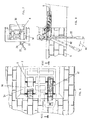
- FIG. 6-9 The embodiment shown in Figure 6-9 is provided to operate a different type of shutter comprising two wing panels which when in the closed configuration lie in the shutter closure plane and when in the open configuration are folded 180° apart in the opposite direction onto the outside of the building.
- the shutter to which this second embodiment of the operating device is applied comprises a first wing panel 54 hinged to the wall and a second wing panel 2 hinged to the first. Consequently the movable frame consists in reality of two frames, namely a frame 8 incorporated in the wing panel 2 and a frame 56 incorporated in the wing panel 54.
- the controlled hinge 12 is in reality formed not only from the two box elements 14 and 16 of the preceding embodiment, but also from an intermediate third box element 58 of length equal to the width of the intermediate frame 56 and welded to it.
- Both the hinged connections between the box element 14 and intermediate element 58 and between said intermediate element 58 and the box element 16 are made by a pair of intermediate rocker arms 60,60' in the manner already described for the preceding embodiment.
- the two intermediate rocker arms 60,60' are also connected together by a pair of bars 62,62' hinged to a further rocker arm 64, which is hinged centrally on a pin 66 fixed to the intermediate box element 58.
- This second embodiment of the device of the invention operates in the following manner: the roto-translational movement of the rocker arm 26 causes the rocker arm 60 hinged to it to undergo roto-translational movement so, by virtue of the coupling between the two rocker arms 60,60', causing this latter to undergo roto-translational movement to roto-translationally move the rocker arm 34.
- the position and dimensions of the various hinge pins are chosen such that on termination of the angular movement of the lever 22 the box element 58 and hence the intermediate wing panel 54 rigid therewith has undergone an outward roto-translational movement through 180°, to lie parallel with and against the wall 6, the box element 16 having undergone a roto-translational movement through 180° in the opposite direction to the intermediate box element 58, so that the shutter 2 lies parallel to and external to the intermediate wing panel 54 (see dashed lines in Figures 8 and 9).
- This embodiment as in the case of the preceding, can also be motorized by replacing the lever 22 for manually operating the bar 24 with a threaded lever operated axially by an electric motor, in the manner as that described with reference to Figure 5.
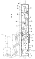
- FIG. 10-13 is again provided for operating shutters with two wing panels which however, instead of being each rotated through 180° in opposite directions in passing from the open configuration to the closed configuration and vice versa to lie one on the other parallel to the outside of the building, are in this case rotated one through 90° in one direction and the other through 180° in the opposite direction so as to be able to lie one on the other within the thickness of the wall in the compartment containing the window unit.
- this embodiment of the device is substantially similar to the preceding, the only difference being a different ratio between the two arm portions of the rocker arm 64 and different parts for hinging the bars 62,62' to the respective intermediate rocker arms 60,60', such that the same roto-translational movement of the rocker arm 26 caused by the lever 22 or alternatively by the electric motor produces a different roto-translational movement of the rocker arm 60, which in this case undergoes a rotation of 90° instead of 180°.
- this movement causes the box element 16 to undergo a roto-translational movement relative to the intermediate box element 58 in which the rotation part of the movement is through 180°.
- FIG. 14-17 The embodiment shown in Figures 14-17 is provided for operating a different type of shutter comprising two wing panels, of which when in the open configuration the first is rotated through 90° from the shutter closure plane and the second is rotated through 90° from the first.
- the bar 24 is connected to the stem 78 of a hydraulic jack.
Landscapes
- Engineering & Computer Science (AREA)
- Mechanical Engineering (AREA)
- Power-Operated Mechanisms For Wings (AREA)
- Operating, Guiding And Securing Of Roll- Type Closing Members (AREA)
- Window Of Vehicle (AREA)
- Wing Frames And Configurations (AREA)
- Closing And Opening Devices For Wings, And Checks For Wings (AREA)
Claims (15)
- Betätigungsvorrichtung für Tür- und Fenster-Einheiten mit angelenkten Flügeltafeln, insbesondere für äußere Fensterläden, dadurch gekennzeichnet, dass sie umfasst:eine Tragstruktur (4), die an der Wand (6) befestigt und an der an einer vertikalen Achse wenigstens eine Flügeltafel (2) angelenkt ist, die zwischen einer geschlossenen Position und einer geöffneten Position bewegbar ist,wenigstens ein Gehäuseelement (16), das in der besagten Flügeltafel (2) vorgesehen ist,einen ersten einarmigen Hebel (26) mit einem ersten Ende, das entlang einem vorgegebenen Weg (32) relativ zu der besagten Tragstruktur (4) zwangsgeführt ist und dessen zweites Ende an dem besagten Gehäuseelement (16) angelenkt ist,einem zweiten einarmigen Hebel (34) mit einem ersten Ende, das entlang einem vorgegebenen Weg (38) relativ zu dem besagten Gehäuseelement (16) zwangsgeführt ist, und dessen zweites Ende an der besagten Tragstruktur (4) angelenkt ist, und dessen mittlerer Abschnitt an dem mittleren Abschnitt des besagten ersten einarmigen Hebels (26) angelenkt ist,einem Betätigungsmittel (22, 24, 48, 52), die das besagten einarmigen Hebel (26) zugeordnet und in dem Sinn wirksam ist, dass es dazu führt, dass das besagte erste Ende entlang dem besagten vorgegebenen Weg (32) relativ zu der besagten Tragstruktur (4) bewegt wird.
- Vorrichtung nach Anspruch 1, dadurch gekennzeichnet, dass die besagte Tragstruktur (4) aus einem äußeren Rahmen besteht.
- Vorrichtung nach Anspruch 1, dadurch gekennzeichnet, dass die Flügeltafel (2) an der Tragstruktur (4) mit einer Vielzahl von Gelenken (10, 12) angelenkt ist, von denen wenigstens eines (10) vom kontrollierten Typ ist.
- Vorrichtung nach Anspruch 3, dadurch gekennzeichnet, dass sie einen bewegbaren Rahmen (8) umfasst, der in die Flügeltafel (2) eingebaut und an der Tragstruktur (4) mit Gelenken (10, 12) angelenkt ist.
- Vorrichtung nach Anspruch 3, dadurch gekennzeichnet, dass das kontrollierte Gelenk (10) aus zwei Gehäuseelementen (14, 16) besteht, wobei das erste (14) an der Tragstruktur (4) befestigt und das zweite in die Flügeltafel (2) eingebaut ist.
- Vorrichtung nach Anspruch 5, dadurch gekennzeichnet, dass das erste Ende des ersten einarmigen Hebels (26) zwangsweise über einen Stift (30) daran in rechteckigen Führungen (32) verschiebbar ist, die an zwei gegenüberliegenden Wänden des Gehäuseelements (14) vorgesehen sind.
- Vorrichtung nach Anspruch 5, dadurch gekennzeichnet, dass das erste Ende des zweiten einarmigen Hebels (34) zwangsweise über einen Stift (36) daran in rechtwinkligen Führungen (28) verschiebbar ist, welche in zwei gegenüberliegenden Wänden des Gehäuseelements (14) vorgesehen sind.
- Vorrichtung nach Anspruch 1, dadurch gekennzeichnet, dass sie einen Betätigungshebel (22) umfasst, der an der Tragstruktur (4) angelenkt und mit dem ersten Ende des ersten einarmigen Hebels (26) verbunden ist.
- Vorrichtung nach Anspruch 8, dadurch gekennzeichnet, dass der Betätigungshebel (22) vom faltbaren Typ ist.
- Vorrichtung nach Anspruch 1, dadurch gekennzeichnet, dass sie eine Stange (24, 48) umfasst, die an das erste Ende des ersten einarmigen Hebels (26) angelenkt und einem Aktuator (52) zugeordnet ist, um das besagte erste Ende entlang dem besagten Weg (32) zu bewegen.
- Vorrichtung nach Anspruch 1, dadurch gekennzeichnet, dass sie einen Elektromotor (52) zur Betätigung eines Schneckenreduziergetriebes aufweist, welches mit einer mit einem Gewinde versehenen axialen Ausnehmung versehen ist, in das eine Gewindestange (48) eingreift, die mit dem ersten einarmigen Hebel (26) verbunden ist.
- Vorrichtung nach Anspruch 1, dadurch gekennzeichnet, dass der erste einarmige Hebel (26) mit einem Block (66) verbunden ist, der mit einem Rohr (68) eine Einheit bildet, welches im Inneren zum Eingriff durch eine Schnecke (70) mit einem Gewinde versehen ist, welche drehbar mit einem Kegelradgetriebesystem (72) verbunden ist, welches durch einen Elektromotor (74) angetrieben wird.
- Vorrichtung nach Anspruch 1, dadurch gekennzeichnet, dass der erste einarmige Hebel (26) mit einem Block (66) verbunden ist, der mit einem Rohr (68) eine Einheit bildet, welches innen zum Eingriff einer Schnecke (70) mit einem Gewinde versehen ist, welche drehbar mit einem Kegelradgetriebesystem (72) verbunden ist, welches durch eine Kurbel (76) angetrieben wird.
- Vorrichtung nach Anspruch 1, dadurch gekennzeichnet, dass der erste einarmige Hebel (26) mit dem Schaft (78) einer hydraulischen Hebeeinrichtung (80) verbunden ist.
- Vorrichtung nach Anspruch 1 zur Betätigung einer Türoder Fenstereinheit mit zwei aneinander angelenkten Flügeltafeln (2, 54), dadurch gekennzeichnet, dass sie umfasst:wenigstens ein kontrolliertes Gelenk (10), das drei Gehäuseelemente (14, 16, 58) umfasst, von denen das erste (14) starr mit einer Tragstruktur (4) verbunden ist, das zweite (16) in die äußere Flügeltafel (2) eingebaut ist und das dritte (58) mit einer Länge, die der Breite der mittleren Flügeltafel (54) entspricht, in die letztere eingebaut ist,einem ersten einarmigen Hebel (26), der ein erstes Ende aufweist, das entlang eines vorgegebenen Weges (32) relativ zu dem ersten Gehäuseelement (14) zwangsgeführt ist, und dessen zweites Ende an dem dritten Gehäuseelement (58) angelenkt ist,einem dritten einarmigen Hebel (60), der ein erstes Ende aufweist, das entlang einem vorgegebenen Weg relativ zu dem dritten Gehäuseelement (58) zwangsgeführt ist, dessen zweites Ende an dem besagten ersten Gehäuseelement (14) angelenkt ist und dessen mittlerer Teil an dem mittleren Teil des besagten ersten einarmigen Hebels (26) angelenkt ist,einem vierten einarmigen Hebel (60'), der ein erstes Ende aufweist, das entlang einem vorgegebenen Weg relativ zu dem besagten dritten Gehäuseelement (58) zwangsgeführt ist, und dessen zweites Ende an dem besagten zweiten Gehäuseelement (16) angelenkt ist,einen zweiten einarmigen Hebel (34), der ein erstes Ende aufweist, das entlang einem vorgegebenen Weg (38) relativ zu dem besagten zweiten Gehäuseelement (16) zwangsgeführt ist, dessen zweites Ende an dem besagten dritten Gehäuseelement (58) angelenkt ist, und dessen mittlerer Teil an dem mittleren Teil des vierten einarmigen Hebels (60') angelenkt ist,einem fünften einarmigen Hebel (64), der in dem zweiten Gehäuseelement (54) aufgenommen ist und Armabschnitte aufweist, die mittels Stangen (62, 62') mit dem ersten Ende des besagten dritten und vierten einarmigen Hebels (60, 60') verbunden sind,Betätigungsmittel (22, 20, 24, 48, 52), die dem besagten ersten einarmigen Hebels (26) zugeordnet sind und in dem Sinne wirken, dass sie dazu führen, dass das besagte erste Ende entlang dem besagten vorgegeberien Weg (32) relativ zu dem besagten ersten Gehäuseelement (14) bewegt wird.
Applications Claiming Priority (2)
| Application Number | Priority Date | Filing Date | Title |
|---|---|---|---|
| IT1998VE000009A IT1306463B1 (it) | 1998-02-20 | 1998-02-20 | Dispositivo di azionamento di serramenti ad ante articolate, inparticolare di serramenti oscuranti esterni. |
| ITVE980009 | 1998-02-20 |
Publications (3)
| Publication Number | Publication Date |
|---|---|
| EP0937852A2 EP0937852A2 (de) | 1999-08-25 |
| EP0937852A3 EP0937852A3 (de) | 1999-09-01 |
| EP0937852B1 true EP0937852B1 (de) | 2003-08-20 |
Family
ID=11424341
Family Applications (1)
| Application Number | Title | Priority Date | Filing Date |
|---|---|---|---|
| EP99102003A Expired - Lifetime EP0937852B1 (de) | 1998-02-20 | 1999-02-01 | Betätigungsvorrichtung für Tür- oder Fensterkonstruktionen mit schwenkbaren Flügelelementen |
Country Status (4)
| Country | Link |
|---|---|
| EP (1) | EP0937852B1 (de) |
| AT (1) | ATE247763T1 (de) |
| DE (1) | DE69910465T2 (de) |
| IT (1) | IT1306463B1 (de) |
Families Citing this family (9)
| Publication number | Priority date | Publication date | Assignee | Title |
|---|---|---|---|---|
| FR2804714B1 (fr) * | 2000-02-04 | 2003-08-15 | Daniel Georges Roger Charton | Fermeture et ouverture automatiques de passages de portes par vantaux articules |
| FR2861790B1 (fr) * | 2003-10-31 | 2006-01-06 | Stremler | Dispositif a plusieurs points de condamnation, notamment pour ouvrant sectionnel |
| CN104799753B (zh) * | 2014-01-23 | 2017-10-31 | 厦门优胜卫厨科技有限公司 | 一种马桶盖板铰链翻盖机构 |
| ITUB20159354A1 (it) * | 2015-12-29 | 2017-06-29 | F A C S R L | Sistema di movimentazione per una barriera a libro e barriera a libro comprendente tale sistema di movimentazione |
| WO2017162662A1 (en) * | 2016-03-22 | 2017-09-28 | Assa Abloy Ab | Access member manipulator and system |
| SE541368C2 (en) | 2017-09-21 | 2019-08-27 | Assa Abloy Ab | Manipulator for an access member, access member comprising the manipulator, system and method |
| EP4019721B1 (de) * | 2020-12-24 | 2023-08-02 | Weider Metal Inc. | Verdecktes scharnier und verdecktes glastürscharnier mit temporärer positionierungsfunktion für den öffnungswinkel |
| WO2024137838A1 (en) * | 2022-12-20 | 2024-06-27 | Liminal Design Inc. | Motorized concealed recessed hinge for swing doors |
| KR20250078018A (ko) * | 2023-11-24 | 2025-06-02 | 현대자동차주식회사 | 차량의 도어힌지 장치 |
Family Cites Families (2)
| Publication number | Priority date | Publication date | Assignee | Title |
|---|---|---|---|---|
| DE1708455A1 (de) * | 1964-05-25 | 1971-05-06 | Paul Zahn | Tuerschliesser |
| GB2183723A (en) * | 1985-11-29 | 1987-06-10 | Securistyle Ltd | Window or door operating mechanism |
-
1998
- 1998-02-20 IT IT1998VE000009A patent/IT1306463B1/it active
-
1999
- 1999-02-01 EP EP99102003A patent/EP0937852B1/de not_active Expired - Lifetime
- 1999-02-01 AT AT99102003T patent/ATE247763T1/de not_active IP Right Cessation
- 1999-02-01 DE DE69910465T patent/DE69910465T2/de not_active Expired - Fee Related
Also Published As
| Publication number | Publication date |
|---|---|
| EP0937852A2 (de) | 1999-08-25 |
| IT1306463B1 (it) | 2001-06-11 |
| ITVE980009A1 (it) | 1999-08-20 |
| DE69910465T2 (de) | 2004-07-01 |
| EP0937852A3 (de) | 1999-09-01 |
| ATE247763T1 (de) | 2003-09-15 |
| DE69910465D1 (de) | 2003-09-25 |
Similar Documents
| Publication | Publication Date | Title |
|---|---|---|
| EP0937852B1 (de) | Betätigungsvorrichtung für Tür- oder Fensterkonstruktionen mit schwenkbaren Flügelelementen | |
| US5253903A (en) | Espagnolette mechanism | |
| US5469658A (en) | Louvre shutter device with variable slats | |
| KR0185243B1 (ko) | 창 또는 문의 슬리브 기어장치 | |
| US4296791A (en) | Folding door or like closure device | |
| KR101874013B1 (ko) | 접이식 도어 장치 | |
| EA010874B1 (ru) | Поворотно-откидное окно с электромоторным приводом с тяговой цепью | |
| RU98116453A (ru) | Окно, дверь или другое подобное изделие с фурнитурной системой | |
| WO1995002106A1 (en) | Window stays | |
| EP1063384A2 (de) | Lüftungsvorrichtung | |
| CZ47893A3 (en) | Drive for bolt rod of a window or door fittings | |
| BE1016457A3 (nl) | Vergrendelmechanisme voor een raam of dergelijke. | |
| DE202008004021U1 (de) | Antriebseinrichtung für einen Flügel eines Fensters oder einer Tür | |
| DE19650190A1 (de) | Dachfenster, insbesondere Schwingflügel-Dachfenster | |
| DE202006014591U1 (de) | Motorischer Antrieb | |
| EP1262621A2 (de) | Antriebseinheit für Tore | |
| EP1180575B1 (de) | Vorsatztür mit Schliessmechanismus | |
| GB2291103A (en) | Espagnolette fastening | |
| KR200165637Y1 (ko) | 여닫이 겸용 미닫이 창호 | |
| DE19827813C2 (de) | Tür- oder Fensterband | |
| AU6243300A (en) | A louvre operating mechanism comprising link members, a rack member and a gear member | |
| DE19606006C5 (de) | Antrieb für einen Flügel eines Fensters, eine Klappe oder dergleichen | |
| HRP950064A2 (en) | Fittings for doors, windows or the like | |
| GB2298232A (en) | Espagnolette locking mechanism with shoot bolts and locking cams | |
| DE202006008411U1 (de) | Anordnung einer Gliederantriebseinrichtung, insbesondere für einen Fensterflügel, eine Klappe oder eine Lichtkuppel |
Legal Events
| Date | Code | Title | Description |
|---|---|---|---|
| PUAI | Public reference made under article 153(3) epc to a published international application that has entered the european phase |
Free format text: ORIGINAL CODE: 0009012 |
|
| PUAL | Search report despatched |
Free format text: ORIGINAL CODE: 0009013 |
|
| AK | Designated contracting states |
Kind code of ref document: A2 Designated state(s): AT BE CH DE DK ES FI FR GB GR IE IT LI LU NL PT SE |
|
| AX | Request for extension of the european patent |
Free format text: AL;LT;LV;MK;RO;SI |
|
| AK | Designated contracting states |
Kind code of ref document: A3 Designated state(s): AT BE CH CY DE DK ES FI FR GB GR IE IT LI LU MC NL PT SE |
|
| AX | Request for extension of the european patent |
Free format text: AL;LT;LV;MK;RO;SI |
|
| 17P | Request for examination filed |
Effective date: 20000122 |
|
| AKX | Designation fees paid |
Free format text: AT BE CH DE DK ES FI FR GB GR IE IT LI LU NL PT SE |
|
| 17Q | First examination report despatched |
Effective date: 20020201 |
|
| GRAH | Despatch of communication of intention to grant a patent |
Free format text: ORIGINAL CODE: EPIDOS IGRA |
|
| GRAS | Grant fee paid |
Free format text: ORIGINAL CODE: EPIDOSNIGR3 |
|
| GRAA | (expected) grant |
Free format text: ORIGINAL CODE: 0009210 |
|
| AK | Designated contracting states |
Designated state(s): AT BE CH DE DK ES FI FR GB GR IE IT LI LU NL PT SE |
|
| PG25 | Lapsed in a contracting state [announced via postgrant information from national office to epo] |
Ref country code: NL Free format text: LAPSE BECAUSE OF FAILURE TO SUBMIT A TRANSLATION OF THE DESCRIPTION OR TO PAY THE FEE WITHIN THE PRESCRIBED TIME-LIMIT Effective date: 20030820 Ref country code: LI Free format text: LAPSE BECAUSE OF FAILURE TO SUBMIT A TRANSLATION OF THE DESCRIPTION OR TO PAY THE FEE WITHIN THE PRESCRIBED TIME-LIMIT Effective date: 20030820 Ref country code: IT Free format text: LAPSE BECAUSE OF FAILURE TO SUBMIT A TRANSLATION OF THE DESCRIPTION OR TO PAY THE FEE WITHIN THE PRE;WARNING: LAPSES OF ITALIAN PATENTS WITH EFFECTIVE DATE BEFORE 2007 MAY HAVE OCCURRED AT ANY TIME BEFORE 2007. THE CORRECT EFFECTIVE DATE MAY BE DIFFERENT FROM THE ONE RECORDED.SCRIBED TIME-LIMIT Effective date: 20030820 Ref country code: FI Free format text: LAPSE BECAUSE OF FAILURE TO SUBMIT A TRANSLATION OF THE DESCRIPTION OR TO PAY THE FEE WITHIN THE PRESCRIBED TIME-LIMIT Effective date: 20030820 Ref country code: CH Free format text: LAPSE BECAUSE OF FAILURE TO SUBMIT A TRANSLATION OF THE DESCRIPTION OR TO PAY THE FEE WITHIN THE PRESCRIBED TIME-LIMIT Effective date: 20030820 Ref country code: BE Free format text: LAPSE BECAUSE OF FAILURE TO SUBMIT A TRANSLATION OF THE DESCRIPTION OR TO PAY THE FEE WITHIN THE PRESCRIBED TIME-LIMIT Effective date: 20030820 |
|
| REG | Reference to a national code |
Ref country code: GB Ref legal event code: FG4D |
|
| REG | Reference to a national code |
Ref country code: CH Ref legal event code: EP |
|
| REG | Reference to a national code |
Ref country code: IE Ref legal event code: FG4D |
|
| REF | Corresponds to: |
Ref document number: 69910465 Country of ref document: DE Date of ref document: 20030925 Kind code of ref document: P |
|
| PG25 | Lapsed in a contracting state [announced via postgrant information from national office to epo] |
Ref country code: SE Free format text: LAPSE BECAUSE OF FAILURE TO SUBMIT A TRANSLATION OF THE DESCRIPTION OR TO PAY THE FEE WITHIN THE PRESCRIBED TIME-LIMIT Effective date: 20031120 Ref country code: GR Free format text: LAPSE BECAUSE OF FAILURE TO SUBMIT A TRANSLATION OF THE DESCRIPTION OR TO PAY THE FEE WITHIN THE PRESCRIBED TIME-LIMIT Effective date: 20031120 Ref country code: DK Free format text: LAPSE BECAUSE OF FAILURE TO SUBMIT A TRANSLATION OF THE DESCRIPTION OR TO PAY THE FEE WITHIN THE PRESCRIBED TIME-LIMIT Effective date: 20031120 |
|
| PG25 | Lapsed in a contracting state [announced via postgrant information from national office to epo] |
Ref country code: ES Free format text: LAPSE BECAUSE OF FAILURE TO SUBMIT A TRANSLATION OF THE DESCRIPTION OR TO PAY THE FEE WITHIN THE PRESCRIBED TIME-LIMIT Effective date: 20031201 |
|
| PG25 | Lapsed in a contracting state [announced via postgrant information from national office to epo] |
Ref country code: PT Free format text: LAPSE BECAUSE OF FAILURE TO SUBMIT A TRANSLATION OF THE DESCRIPTION OR TO PAY THE FEE WITHIN THE PRESCRIBED TIME-LIMIT Effective date: 20040120 |
|
| PG25 | Lapsed in a contracting state [announced via postgrant information from national office to epo] |
Ref country code: LU Free format text: LAPSE BECAUSE OF NON-PAYMENT OF DUE FEES Effective date: 20040201 Ref country code: GB Free format text: LAPSE BECAUSE OF NON-PAYMENT OF DUE FEES Effective date: 20040201 |
|
| NLV1 | Nl: lapsed or annulled due to failure to fulfill the requirements of art. 29p and 29m of the patents act | ||
| PG25 | Lapsed in a contracting state [announced via postgrant information from national office to epo] |
Ref country code: IE Free format text: LAPSE BECAUSE OF NON-PAYMENT OF DUE FEES Effective date: 20040202 |
|
| REG | Reference to a national code |
Ref country code: CH Ref legal event code: PL |
|
| PGFP | Annual fee paid to national office [announced via postgrant information from national office to epo] |
Ref country code: AT Payment date: 20040301 Year of fee payment: 6 |
|
| ET | Fr: translation filed | ||
| PLBE | No opposition filed within time limit |
Free format text: ORIGINAL CODE: 0009261 |
|
| STAA | Information on the status of an ep patent application or granted ep patent |
Free format text: STATUS: NO OPPOSITION FILED WITHIN TIME LIMIT |
|
| 26N | No opposition filed |
Effective date: 20040524 |
|
| GBPC | Gb: european patent ceased through non-payment of renewal fee |
Effective date: 20040201 |
|
| REG | Reference to a national code |
Ref country code: IE Ref legal event code: MM4A |
|
| PG25 | Lapsed in a contracting state [announced via postgrant information from national office to epo] |
Ref country code: AT Free format text: LAPSE BECAUSE OF NON-PAYMENT OF DUE FEES Effective date: 20050201 |
|
| PG25 | Lapsed in a contracting state [announced via postgrant information from national office to epo] |
Ref country code: FR Free format text: LAPSE BECAUSE OF NON-PAYMENT OF DUE FEES Effective date: 20051031 |
|
| REG | Reference to a national code |
Ref country code: FR Ref legal event code: ST Effective date: 20051031 |
|
| REG | Reference to a national code |
Ref country code: FR Ref legal event code: RN |
|
| REG | Reference to a national code |
Ref country code: FR Ref legal event code: D3 |
|
| PGFP | Annual fee paid to national office [announced via postgrant information from national office to epo] |
Ref country code: DE Payment date: 20080131 Year of fee payment: 10 |
|
| PGFP | Annual fee paid to national office [announced via postgrant information from national office to epo] |
Ref country code: FR Payment date: 20080201 Year of fee payment: 10 |
|
| REG | Reference to a national code |
Ref country code: FR Ref legal event code: ST Effective date: 20091030 |
|
| PG25 | Lapsed in a contracting state [announced via postgrant information from national office to epo] |
Ref country code: DE Free format text: LAPSE BECAUSE OF NON-PAYMENT OF DUE FEES Effective date: 20090901 |
|
| PG25 | Lapsed in a contracting state [announced via postgrant information from national office to epo] |
Ref country code: FR Free format text: LAPSE BECAUSE OF NON-PAYMENT OF DUE FEES Effective date: 20090228 |