EP0936612A2 - Méthode d'enregistrement/de reproduction pour disque optique, disque optique et dispositif pour disque optique - Google Patents
Méthode d'enregistrement/de reproduction pour disque optique, disque optique et dispositif pour disque optique Download PDFInfo
- Publication number
- EP0936612A2 EP0936612A2 EP99301096A EP99301096A EP0936612A2 EP 0936612 A2 EP0936612 A2 EP 0936612A2 EP 99301096 A EP99301096 A EP 99301096A EP 99301096 A EP99301096 A EP 99301096A EP 0936612 A2 EP0936612 A2 EP 0936612A2
- Authority
- EP
- European Patent Office
- Prior art keywords
- code
- data
- length
- sectors
- optical disc
- Prior art date
- Legal status (The legal status is an assumption and is not a legal conclusion. Google has not performed a legal analysis and makes no representation as to the accuracy of the status listed.)
- Withdrawn
Links
Images


Classifications
-
- H—ELECTRICITY
- H03—ELECTRONIC CIRCUITRY
- H03M—CODING; DECODING; CODE CONVERSION IN GENERAL
- H03M13/00—Coding, decoding or code conversion, for error detection or error correction; Coding theory basic assumptions; Coding bounds; Error probability evaluation methods; Channel models; Simulation or testing of codes
- H03M13/27—Coding, decoding or code conversion, for error detection or error correction; Coding theory basic assumptions; Coding bounds; Error probability evaluation methods; Channel models; Simulation or testing of codes using interleaving techniques
- H03M13/276—Interleaving address generation
-
- G—PHYSICS
- G11—INFORMATION STORAGE
- G11B—INFORMATION STORAGE BASED ON RELATIVE MOVEMENT BETWEEN RECORD CARRIER AND TRANSDUCER
- G11B20/00—Signal processing not specific to the method of recording or reproducing; Circuits therefor
- G11B20/10—Digital recording or reproducing
- G11B20/18—Error detection or correction; Testing, e.g. of drop-outs
- G11B20/1866—Error detection or correction; Testing, e.g. of drop-outs by interleaving
-
- H—ELECTRICITY
- H03—ELECTRONIC CIRCUITRY
- H03M—CODING; DECODING; CODE CONVERSION IN GENERAL
- H03M13/00—Coding, decoding or code conversion, for error detection or error correction; Coding theory basic assumptions; Coding bounds; Error probability evaluation methods; Channel models; Simulation or testing of codes
- H03M13/27—Coding, decoding or code conversion, for error detection or error correction; Coding theory basic assumptions; Coding bounds; Error probability evaluation methods; Channel models; Simulation or testing of codes using interleaving techniques
-
- G—PHYSICS
- G11—INFORMATION STORAGE
- G11B—INFORMATION STORAGE BASED ON RELATIVE MOVEMENT BETWEEN RECORD CARRIER AND TRANSDUCER
- G11B7/00—Recording or reproducing by optical means, e.g. recording using a thermal beam of optical radiation by modifying optical properties or the physical structure, reproducing using an optical beam at lower power by sensing optical properties; Record carriers therefor
- G11B7/007—Arrangement of the information on the record carrier, e.g. form of tracks, actual track shape, e.g. wobbled, or cross-section, e.g. v-shaped; Sequential information structures, e.g. sectoring or header formats within a track
Definitions
- the present invention relates to an optical disc recording/reproducing method, an optical disc and to an optical disc device.
- an optical recording medium such as a disc-shaped recording medium or a card-shaped recording medium, employing an optical or magneto-optical signal recording/reproducing method
- a disc-shaped recording medium or a card-shaped recording medium employing an optical or magneto-optical signal recording/reproducing method
- an optical recording medium such as a disc-shaped recording medium or a card-shaped recording medium, employing an optical or magneto-optical signal recording/reproducing method
- read-only type recording mediums such as the so-called compact discs
- write-once type recording mediums on which the user can write only once and an overwrite type recording mediums, on which the information can be rewritten, such as a magneto-optical disc.
- an overwrite type recording mediums on which the information can be rewritten, such as a magneto-optical disc.
- An optical disc device for data writing/readout for a disc-shaped recording medium encloses a laser diode for radiating a light beam for information recording/reproduction and a photodetector for detecting the reflected light ofthe light beam illuminated n the optical disc and is adapted for recording/reproducing data by scanning the recording track ofthe optical disc with a light beam, using an optical head focussing-servo or tracking-servo controlled, based on a detection output of the photodetector, as the speed servo is applied to the spindle motor to run the optical disc run in rotation at a constant angular velocity or at a constant linear velocity.
- blocked codes are used in a magneto-optical disc system prescribed in International organization for Standardization (ISO).
- the direction ofuser data is the data direction on a disc, as shown in Fig.1.
- the direction of the correction code is interleaved with reference to the data direction on the disc for elevating the burst error correction capability.
- data directly following the frame sync FS belongs to the same error correction code
- the second data from the frame sync FS belongs to the separate same error correction code
- so forth until the data directly previous to the frame sync FS belongs to the still separate same error correction code.
- an ECC processor 303 starts error correction coding.
- the encoded data is sent from the buffer memory 302 to modulation means to start channel encoding. It is this channel-encoded data that is recorded on the user data area on the disc.
- the ECC processor 303 starts decoding.
- user data is retrieved from the buffer memory 302 and sent to the application side.
- the spot size on a recording medium can be reduced by the technique of using a short wavelength semiconductor laser light source, such as GaN or ZnSe, or the technique of enlarging the NA of an objective lens by a double lens set exemplified by a solid immersion lens (SIL).
- a short wavelength semiconductor laser light source such as GaN or ZnSe
- SIL solid immersion lens
- the spot diameter is approximately 0.75 ⁇ m on the recording medium, such that, if signals are recorded or reproduced using, for example, the RLL(1,7) modulation, the recording line density of the order of 0.21 ⁇ m/bit can be achieved.
- the representative modulation code of the modulation system of the broad channel detection window suited for high density recording/reproduction there are known the RLL(1,7) code or the RLL(2,7) code.
- the block size exceeding 64 kB as user data can be constructed even with the use of the GF(2 8 ) routinely used as a code.
- the number of symbols of the C1 correction code and the C2 correction code is up to a maximum of 255 in the case of the product code (PRC) employing the GF(2 8 ).
- the interleaving length is up to a maximum of 255+1 such that it cannot be extended limitlessly.
- the code length can be lengthened by limiting C1 only to the code for detection, C2 needs to be a correction code in order to effect error correction. Therefore, none ofthe C2 code, C1 code nor the interleaving length can be lengthened with a routine method.
- An embodiment of the present invention seeks to provide an optical disc recording/reproducing method, an optical disc and an optical disc device in which a logical format of a product code is constructed for enabling the long interleaving by a large block to enable data recording/reproduction to high reliability.
- Another embodiment of the present invention seeks to provide an optical disc recording/reproducing method, an optical disc and an optical disc device in which recording/reproduction of data of sufficiently high reliability for normal use is enabled at a high transfer rate.
- Yet another embodiment of the present invention seeks to provide an optical disc recording/reproducing method, an optical disc and an optical disc device in which data can be recorded/reproduced with plural logical formats having the same physical format and different block sizes.
- the error correction code C1 takes a line in the vertical direction, against the oblique data direction on the disc, as indicated by the data direction on the disc and the code direction (correction line) in Fig. 39, and the error correction code C1 is interleaved.
- a number of the interleaved error correction codes C1 are bundled to form an ECC block, on which a second code C2 having the data direction different from the error correction code C1 is constituted, as shown in Fig.40.
- the data on the disc is in the oblique direction, while the interleaving direction with respect to the first error correction code C1 is in the horizontal direction, so that the interleaving length can be increased.
- a product code PCR
- the second code C2 in this ECC block has its direction coincident with the data direction on the disc, it is possible to start the encoding at a time point the data required for encoding one ECC block is readied and to record data on the disc at a time point when the encoding for one ECC block comes to a close. Also, during reproduction, it is possible to start the correcting operation for the playback data as from the time point when the data for one ECC block has been sent from the demodulator and to send out user data as from a time point the correction for one code comes to a close.
- the present invention provides, in one aspect, a recording/reproducing method for an optical disc in which data is recorded/reproduced by a disc format in which an ECC block formed by a first error correction code interleaved with respect to the direction of data on the disc and a second code having the direction of the data different from that of the first error correction code is made up of one or more sectors, the sector is made up of a plurality of sectors, the block length of the ECC block is set so that
- the present invention provides an optical disc having a disc format in which an ECC block formed by a first error correction code interleaved with respect to the direction of data on the disc and a second code having the direction of the data different from that of the first error correction code is made up of one or more sectors, the sector is made up of a plurality of sectors, the block length of the ECC block is set so that
- the present invention provides an optical disc device for recording/reproducing data by a disc format in which an ECC block formed by a first error correction code interleaved with respect to the direction of data on the disc and a second code having the direction of the data different from that of the first error correction code is made up of one or more sectors, the sector is made up of a plurality of sectors, the block length of the ECC block is set so that
- the data is recorded/reproduced by a disc format in which the direction of the second code is caused to coincide with the data direction on the disc.
- the data is recorded/reproduced by a disc format in which the code length of the second code is the information word length of the first error correction code.
- the direction of the second code is interleaved by a length equal to the segment length.
- the data is recorded/reproduced by a disc format having a sector ID such that
- the data is recorded/reproduced by a disc format in which the parity of the second code is arrayed in the sector ID.
- the data is recorded/reproduced by a disc format in which the information word of the second code is made up only of user data or of the user data and the parity of the first error correction code, without changing block size of the ECC block.
- an optical disc recording/reproducing method, an optical disc and an optical disc device may be provided in which a logical format which has enabled long interleaving is constituted by a large block to enable data recording/reproduction to high reliability.
- an optical disc recording/reproducing method, an optical disc and an optical disc device may be provided in which data of sufficiently high reliability for ordinary use may be recorded/reproduced at a high transfer rate.
- an optical disc recording/reproducing method an optical disc and an optical disc device may also be provided in which data may be recorded or reproduced at a high transfer rate.
- an optical disc recording/reproducing method, an optical disc and an optical disc device may also be provided in which data may be recorded or reproduced with plural logical formats of different block sizes with the same physical format.
- Fig. 1 schematically shows a frame structure in an ECC block in a format of a magneto-optical disc prescribed in ISO.
- Figs.2A and 2B are schematic views showing the flow of data in the recording/reproducing operation for a magneto-optical disc prescribed in ISO.
- Fig.3 shows a block structure of the product code known up to now.
- Fig.4 shows an ECC block structure of a DVD.
- Fig.5 is a schematic view showing the structure of an ECC block in an optical disc system embodying the present invention.
- Figs.6A and 6B are schematic views showing the structure of an ECC block in an optical disc system shown in Fig.5.
- Fig.7 is a schematic view showing a data structure in a sector in an optical disc system employing the ECC block.
- Fig. 8 is a schematic view showing the relation between the data structure in the sector and the ECC (made up of the information word and the parity).
- Fig.9 is a schematic view showing the frame structure in the ECC block.
- Fig. 10 is a schematic view showing an array and the structure of data units in the ECC block.
- Fig. 11 is a schematic view showing the structure of user data in the optical system shown in Fig.5.
- Fig. 12 is a schematic view showing the frame structure in the ECC block in case an ECC block is constituted by one sector.
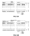
- Figs. 13A and 13B are schematic views showing another frame structure in the ECC block.
- Fig. 14 is a schematic view showing the data structure in a sector in case of the frame structure shown in Fig. 13.
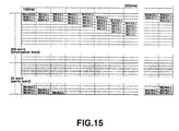
- Fig. 15 is a schematic view showing the relation between the data structure in a sector and the ECC (made up of the information word and the parity) in case of the frame structure shown in Fig. 13.
- Fig. 16 is a schematic view showing an array and the structure of data units in the ECC block in case of the frame structure shown in Fig.13.
- Fig. 17 is a block diagram showing the structure of a disc drive of an optical disc recording/reproducing apparatus for recording/reproducing user data for an optical disc of the format shown in Fig. 1.
- Fig. 18 is a schematic cross-sectional view showing the structure ofan aspherical double-lens type objective lens unit provided on an optical head of the disc drive shown in Fig.18.
- Fig. 19 is a block diagram showing a recording/reproducing processing block in the optical disc recording/reproducing apparatus shown in Fig. 17.
- Figs.20A and 20B are schematic views the data flow in the recording/reproducing operation by the optical disc recording/reproducing apparatus shown in Fig.17.
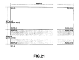
- Fig.21 is a schematic view showing another structure of an ECC block in the optical disc system embodying the present invention.
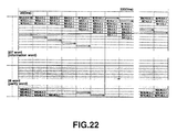
- Fig.22 is a schematic view showing a frame structure in the ECC block shown in Fig.21.
- Fig.23 is a schematic view showing an array and the structure of a data unit in the ECC block shown in Fig.21.
- Fig.24 is a schematic view showing another structure of an ECC block in the optical disc system embodying the present invention.
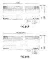
- Figs.25A, 25B are schematic views showing the frame structure in the ECC block shown in Fig.24.
- Fig.26 is a schematic view showing the data structure in a sector in an optical disc system employing the ECC block shown in Fig. 14.
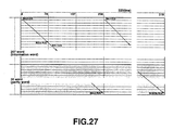
- Fig.27 is a schematic view showing the frame structure in the ECC block shown in Fig.24.
- Fig.28 is a schematic view showing an array and the structure of a data unit in the ECC block shown in Fig.24.
- Fig.29 shows an illustrative structure of an ECC block embodying the present invention.
- Fig.30 shows an ECC block of the block format which is to be the basis of the ECC block shown in Fig.29.
- Fig.31 illustrates the structure of the second C2 code of the ECC block shown in Fig.29.
- Fig.32 shows another illustrative structure of the ECC block embodying the present invention.
- Fig.33 shows an ECC block of the block format which is to be the basis of the ECC block shown in Fig.32.
- Fig.34 shows the structure ofthe second code C2 in case the code length ofthe second code C2 is the information word length of the first correction code C1 multiplied by the segment length by applying an embodiment of the present invention to the ECC block shown in Fig. 32.
- Figs.35A, 35B schematically show the data flow in the usual recording mode and the high-speed recording mode in case the user data direction is set to the direction of the first correction code C1 in the optical disc recording/reproducing apparatus embodying the present invention.
- Figs.36A, 36B are schematic views showing the data flow in the usual reproducing mode and in the high-speed reproducing mode in case the user data direction is the direction of the first correction code C1 in the optical disc recording/reproducing apparatus embodying the present invention.
- Fig.37 is a schematic view showing the data flow in the recording mode in case the user data direction is the direction of the second correction code C2 in the optical disc recording/reproducing apparatus embodying the present invention.
- Figs.38A, 38B are schematic views showing the data flow in the usual reproducing mode and in the high-speed reproducing mode in case the user data direction is the direction of the second correction code C2 in the optical disc recording/reproducing apparatus embodying the present invention.
- Fig.39 schematically shows the structure of an ECC block in which the user data direction is equated to the correction code direction.
- Fig.40 shows the operating timings in an optical disc system for a conventional ECC block in which the user data direction is different from the correction code direction, an ECC block in which the user data direction is equated to the correction code direction and a conventional ECC block in which the user data direction is different from the correction code direction.
- an ECC block of the block format as shown for example in Fig.5 is used.
- the number of data of a frame of the ECC block is 100 bytes, as shown by the frame structure in Fig.6A.
- (1, 7) modulation for example, the 100 bytes per frame is turned into 1200 channels, as shown in Fig.6B.
- B(s, t, u, v) is modulated to m(s, t, u, w), where s, t, u, v and w stand for a sector, a frame, a segment, a data (byte) and an as-modulated channel. It is also possible to provide a DCC channel for appending the DCC code on the dc control (DCC) cell unit to control the dc component in the above (1, 7) modulation system.
- DCC dc control
- Each segment is equivalent to 20 bytes equal to a sector ID length. Since each segment is of a length of 20 bytes corresponding to the length of the sector ID length, so that the number of segments in a frame is 5.
- the number of sectors in this ECC block is 16, with the number of frames per sector being 47 and with the volume of user data per sector being equivalent to 4 KB.
- a frame sync FS is attached to the leading end of a frame (frame(channel)) based channel string
- APC and VFO are attached to the leading end of 47 frames (frame(channel))
- a post-amble PO is attached to complete a sector.
- APC is a light-emitting pattern area for controlling the recording laser power during recording
- VFO is a pattern area for applying the PLL for clock extraction during reproduction.
- the frame sync FS there is used a unique pattern that is not used in the modulation rule of applying the channel synchronization.
- a frame sync FS0 indicating the leading end of a sector and other frame syncs FS1 are demarcated from each other.
- a sector sync SS may be inserted between the VFO and FS.
- the data direction of data on the disc is accorded by setting the arraying number from the upper order side to the lower order side in the rising sequence of B(s, t, u, v), that is in the sequence of s, t, u and v.
- the leading segment of the leading frame of each sector is the sector ID.
- the sector ID corresponds to the first word in the information words of all correction codes
- user data corresponds to the second and the following words in the information words of all correction codes.
- the user data direction may be equated to the correction code direction without obstruction by the header.
- H(g, h) is the header information, that is the sector ID information
- U(g,h) is user data
- E(g,h) is the error correction code for user data
- g and h are the number of data units and the number of data, respectively.
- the direction of ECC (error detecting direction) may be the same as the ECC code direction. However, error detection by the EDC is performed on the entire data of the data unit, that is user data and EDC.
- the EDC is generated so as to satisfy the following equation (2):
- the above header information H(g,h) contains the information used as ID in a CPU of a controller.
- a portion of the header information is occasionally used as a physical address information, such as a sector.
- the header information may also contain the information, such as the disc foreword, to which can be added the error detection code.
- an area for dummy data for substitution for the synchronization pattern is contained in the sector ID. This has no meaning for the application side, or the CPU of the controller.
- the results detected by the error detection code E(g,h) and the user data U(g,h) are used, for example, by the CPU ofthe controller. It is however sufficient if only the user data U(g,h) is sent to the application side.
- the array in which the direction of the user data U(g,h) is equated to the direction of the detection code E(g,h) may be expressed in terms of the relation of D(i,j) and E(g,h) by where h is 0 to 4095 and g is 0 to 15; and where h is 0 to 3 and g is 0 to 15.
- header information H(g,h) where h is 0 to 19 and g is 0 to 15.
- user data can immediately be sent to the application side if correction is made only for the required portion followed by EDC check. That is, it suffices if correction is made for the data unit, it being unnecessary to wait for the correction for one block.
- the error correction code may be generated, as the user data is being sent from the application side.
- a parity word for a code can be generated at a time point when the information words for the code have been sent.
- the error correction code EDC can also be generated at a time point when user data for one data unit have been sent.
- the error correction code EDC can be generated by performing the EDC generating operation as the user data is being sent, by carrying out an arithmetic operation on the information words sent for the user data portion of the error correction code, and by carrying out an arithmetic operation on the generated parity for the parity word.
- a number of the leading end data (B(x,x,00)) of the leading end of each frame, that is the leading segment, corresponding to the number of sectors, are distributed every segment length, so that the leading end data is distributed in 16 codes every 20 fines in the interleaving length.
- the data in specified positions in the frame may be prevented from being concentrated in specified codes to prevent the occurrence of correction impossibilities to assure invulnerability against errors that might produce bit slip.
- the above-mentioned sectors may be collected together to provide an actual header.
- Fig.12 shows a frame structure in an ECC block in case an ECC block is constituted by a sector.
- data of a sector make up an ECC block
- the user data of the ECC block constitutes on data unit.
- the data direction in a data unit may be the same as the ECC direction.
- Figs.13A and 13B show the frame structure in the ECC block in case the number of sectors is 32, with the ECC block structure being the same as that shown in Fig.3.
- the address information is contained in a segment.
- FIG.14 showing the data structure in a sector, the number of sectors in an ECC block is 32.
- the frame structure in the ECC block is shown in Fig.15.
- the number of data units in an ECC block is 16.
- the address information of a sector 0 and that of a sector 1 are set to H(0, 0 to 9) and H(0, 10 to 19), respectively, or to obtain the information necessary for ID to produce the ID information for the data unit 0.
- the present optical disc recording/reproducing apparatus has a disc drive 100 of a structure shown in Fig. 17, and scans the information recording surface of an optical disc 101 by an optical head 110 with a laser light beam to optically record/reproduce the information as the disc is run in rotation by a spindle motor 102 at, for example, a constant angular velocity.
- the optical head 110 provided in the disc drive 100, includes a semiconductor laser (LD) 103 as a light source for radiating the recording/reproducing laser light to the optical disc 101.
- the radiated light beam from the semiconductor laser 103 is collimated by a collimator lens 104 to traverse a diffraction grating 105 used for generating a side spot.
- the light beam then falls on an aspherical double-lens unit 120 via a beam splitter 106 and a quarter wave plate 107 so as to be then converged on an information recording surface of the optical disc 101.
- a portion of the outgoing light from the semiconductor laser 103 is reflected by the beam splitter 106 and sent via a converging lens 108 to a light emission power monitoring detector 109 so as to be used for automatic power control (APC) for controlling the laser power on the information recording surface.
- the reflected light from the optical disc 101 that is playback signals, are reflected by the beam splitter 106 and thence fed via converging lens 112 and a cylindrical lens 103 to a servo signal detector 114 for electro-optical conversion.
- the remaining portion of the reflected light falls on an RF signal detector 117 via lenses 115, 116 for electro-optical conversion.
- This optical head 110 generates focussing error signals using an astigmatic method, while generating tracking error signals using a differential push-pull method.
- the servo error signals and the playback RF signals are detected by the two signal detectors 14, 117, a sole detector may be used for this purpose.
- the aspherical double-lens unit 120 includes a first electro-magnetic actuator 122 for driving a first lens 121, and a second electro-magnetic actuator 124 for driving a second lens 123, as shown in Fig.18.
- the second lens 123 is loaded on the second electro-magnetic actuator 124 movable along the optical axis direction and along the track direction, and has a numerical aperture approximately equal to 0.5.
- the first lens 121 is mounted on top of the second lens 123 on the first electro-magnetic actuator 122 distinct from the second electro-magnetic actuator 124 whereby it can be moved in a controlled manner to an optional position on the optical axis.
- This optical disc recording/reproducing apparatus includes a recording/reproducing processing block 200, configured as shown in Fig.17, connected to the disc drive 100 adapted for scanning the information recording surface of the optical disc 101 by the optical head 110 for recording/reproduction.
- This recording/reproducing processing block 200 includes a computer (central processing unit (CPU) 202 for exchanging user data and control data with the application side via an application I/F circuit 201, and an arbitration processor 203 .
- CPU central processing unit
- arbitration processor 203 To the arbitration processor 203, there are connected not only a buffer memory 204 and an ECC processor 205 but also an in-sector timing generator 206 and a playback timing generator 207.
- the recording/reproducing processing block 200 includes a modulator 208, fed with recording data from the arbitration processor 203 during recording, a pattern generator 211 and a selector 212, both actuated responsive to timing signals applied from the in-sector timing generator 206.
- the modulator 208 modulates recording data sent from the arbitration processor 203 in accordance with the RLL(1,7) modulation rule to send the modulation output to the selector 212.
- the pattern generator 211 generates APC, VFO and PO patterns.
- the selector 212 is responsive to timing signals sent from the in-sector timing generator 206 to select outputs of the modulator 208 or the pattern generator 211 to send recording channel signals which are sent to the disc drive 100.
- the in-sector timing generator 206 RLL(2,7) demodulates playback signals of an address area (sector ID area) AR2 of the optical disc 21 sent from the disc drive 100 to produce the address information which is sent as the sector position information to the CPU 202. Also, the in-sector timing generator 206 generates timing signals in the sector based on the sector position information in order to control the operation of the modulator 208, pattern generator 211 and the selector 212 during recording and in order to send reference timing signals to the playback timing generator 207 during reproduction.
- the CPU 202 performs accessing control for recording/reproducing user data based on the control data sent from the application side and the sector position information sent from the in-sector timing generator 206.
- the recording/reproducing processing block 200 is further provided with a synchronization detector 213 and a demodulator 214 both of which are fed with playback channel signals from the disc drive 100 during reproduction.
- the synchronization detector 213 detects the synchronization signals contained in the playback channel signals to send the detected synchronization signals to the playback timing generator 207.
- the demodulator 214 processes the playback channel signals with RLL(1,7) demodulation associated with the RLL(1,7) modulation by the modulator 208 to generate playback data which is sent to the arbitration processor 203.
- user data is sent from the application side to the ECC processor 205, while the ID information and reserve data are sent from the CPU 202 , during recording, as shown in Fig.20A.
- the ECC processor 205 generates the IDE and EDC which are further ECC encoded to provide data in the ECC block on the buffer memory 204.
- the e205 starts the encoding at a time point the data necessary ir generating a code is sent thereto, without waiting until user data for a single ECC block is provided on the buffer memory 204.
- the data in the ECC block provided on the buffer memory 204 is RLL(1,7)-modulated by the modulator 208 at a timing of a sector for recording, indicated by the timing signals from the in-sector timing generator 206.
- the modulated data is turned by the selector 212 into recording channel signals, having appended thereto the APC, VFO, SS and PO patterns generated by the pattern generator 211.
- the recording channel signals, thus generated are sent to the disc drive 100 for recording on a user area ofthe optical disc 101.
- the arbitration processor 203 arbitrates address signals for the buffer memory, generated from the respective blocks, to re-array the data.
- the arbitration processor 203 detects synchronization signals by the synchronization detector 213 from the reproduced playback channel signals to send the detected synchronization signals to the playback timing generator 207 by way of synchronization protection. Based on the timing ofthe playback timing generator 207, the arbitration processor 203 RLL(1,7) demodulates the playback channel signals by the demodulator 214 to send the playback data to the buffer memory 204, as shown in Fig.20B.
- the ECC processor 205 ECC decodes the playback data to perform EDC check and also IDE check.
- the ECC processor 205 corrects the playback data for errors, and sends out user data as from a time point the correction of a sole code has come to a close. That is, there is no necessity for waiting for correction for one ECC block.
- the code position (word) is updated in terms of a segment, corresponding to the length of a header, that is a sector ID, as a unit. It is however sufficient if the number of data in the segment is selected to be smaller than the number of data in the frame, and if, in associating the data position on the disc with the data position on the ECC block, the correction code position is updated on the segment basis, such that the interleaving rule is met.
- an ECC block with a code length of 235 (207 information words and 28 parity words) comprised of 320 lines of codes, each being made up of 207 information words and 28 parity words, with an interleaving length being 320, as shown in Fig.21, is such a block data in which the ECC block has a frame structure shown in Fig.6 to assume the data structure in a sector shown in Fig.7.
- the ECC block shown in Fig.5 is tantamount to a block in which the number of sectors is 16, the number of frames is 47, the frame length is 100 bytes, the code length is 235, interleaving length is 320, sector ID is 20, k is 1, segment length is 20, p is 1 and the number of sub-sectors is 16.
- the user data in the ECC block is 64KB and the number of constituent sectors is 16.
- H(g,h) is the header information, that is sector ID information
- R(g,h) is the 20-byte information at the leading end of each sector
- U(g,h) is user data
- E(g,h) is the error detection code EDC for user data, with g and h being the number of data units and the number of data, respectively.
- the data direction of data on the disc is accorded by setting the arraying number from the upper order side to the lower order side in the rising sequence of B(s, t, u, v), that is in the sequence of s, t, u and v.
- header information H(g,h) where h is 0 to 19 and g is 0 to 15.
- specified data in a frame for example, leading end data of a frame R(g,h), are distributed in sixteen positions every 20 codes.
- the sector ID is at the leading end 20 bytes of each sector.
- the ECC block shown in Fig. 12 constituting a sole ECC block by one sector, is tantamount to a block in which the number of sectors is 1, the number of frames is 47, the frame length is 100 bytes, the code length is 235, interleaving length is 20, sector ID is 20, k is 1, segment length is 20 p is 1 and the number of sub-sectors is 1.
- the user data in the ECC block is 4 KB and the number of constituent sectors is 1.
- the leading end data of a frame R(g,h), are distributed in one position every 20 codes.
- the sector ID is at the leading end 20 bytes of each sector.
- the ECC block shown in Figs.13 to 16 constituting a sole ECC block by one sector, is tantamount to a block in which the number of sectors is 32, the number of frames is 47, the frame length is 50 bytes, the code length is 235, interleaving length is 320, sector ID is 10, k is 1, segment length is 10, p is 1 and the number of sub-sectors is 32.
- the user data in the ECC block is 64 KB and the number of constituent sectors is 32.
- the leading end data of a frame R(g,h), are distributed in 32 positions every 10 codes.
- the sector ID is at the leading end 10 bytes of each sector.
- the user data in the ECC block is 64 KB
- the number of constituent sectors is 16 so that the sector Ids are concentrated.
- the number of sectors is 16
- the number of frames is 100
- the frame length is 47 bytes
- the code length is 235
- interleaving length is 320
- sector ID is 20
- k is 1
- segment length is 5
- p is 4
- the number of sub-sectors is 64
- the frame leading end data R(g,h) are distributed at 64 places every five codes
- the number of user data in the ECC block equal to 64 KB and with the number of constituent sectors being 16.
- the sector IDs are distributed at four places every 5 bytes.
- the frame leading end data R(g,h) are distributed at 32 places every 10 codes, with the number of user data in the ECC block equal to 64 KB and with the number of constituent sectors being 16.
- the sector IDs are distributed at two places every ten bytes.
- an ECC block with a code length of 237 made up of 207 information words and 30 parity words, with the interleaving length being 320, obtained by arraying 320 lines each being made up of 207 information words and 30 parity words to form a blocked data, as shown in Fig.24
- 79 bytes of one frame data of the ECC block, the frame structure of which is shown in Fig.25A, are converted by (1,7) modulation into 948 channels, as shown in Fig.25B.
- B(s, t, u, v) is modulated to m(s, t, u, w), where s, t, u, v are a sector, a frame, a segment and data, respectively, while w denotes the as-modulated channel. It is also possible to provide a DCC channel in which a DCC code is attached on the dc control cell basis n order to control the dc components n the (1,7) modulation system.
- a frame sync FS is attached to the leading end of a frame channel based channel string, and APC and VFO are attached to the leading end of the 47 frame (frame(channel)) .
- a post-amble PO is attached to constitute a sector.
- the APC is a light emitting pattern area for controlling the recording laser power during recording
- the VFO is a pattern area for applying the PLL for clock extraction during reproduction.
- the frame sync FS there is used a unique pattern not used in the modulation rule used in turn for applying channel synchronization.
- the frame sync FS0 indicating the leading end of a sector is distinguished from other frame syncs FS1 in the frame sync FS.
- a sector sync SS may be inserted between the VFO and the FS.
- the number of sectors, the number of frames, the frame length, the code length, interleaving length, sector ID, k, segment length, p and the number of sub-sectors are set to 16, 60, 79, 237, 320, 20, 1, 1, 20 and 320.
- the correction code position is updated from segment to segment, as the interleaving rule is met.
- This disc format renders it possible to associate the disc data on the data on the ECC block in a one-for-one correspondence.
- the frame structure in the ECC block is shown in Fig.27.
- the data direction of data on the disc is accorded by setting the arraying number from the upper order side to the lower order side in the rising sequence of B(s, t, u, v), that is in the sequence ofs, t, u and v.
- one-block data on the disc can be associated with the totality of data on the ECC block in a one-for-one correspondence.
- the header that is the sector ID
- user data corresponds to the second and the following words in the information words of all correction codes.
- the user data direction may be equated to the correction code direction without obstruction by the header.
- H(g, h) is the header information, that is the sector ID information
- R(g,h) is the leading 20 byte information of each sector
- U(g,h) is user data
- E(g,h) is the error correction code for user data
- g and h are the number of data units and the number of data, respectively.
- the data direction of data on the disc is accorded by setting the arraying number from the upper order side to the lower order side in the rising sequence of B(s, t, u, v), that is in the sequence of s, t, u and v.
- header information H(g,h) where h is 0 to 19 and g is 0 to 15.
- the number of user data in the ECC block is 64 KB, and the number of constituting sectors is 16, such that the frame leading data R(g,h) is distributed uniformly at 320 places in each code.
- the sector IDs are distributed on the byte basis.
- the number of sub-sectors is 320, and the frame leading data R(g,h) is adapted to be distributed evenly at 320 places in each code.
- the number of sub-sectors equal to 160, with the number of sectors, number of frames, frame length, code length, interleaving length, sector ID, k, segment length, p and the number of sub-sectors equal to 16, 60, 158 bytes, 237, 320, 20, 1, 1 and 20 and 160, respectively
- the number of user data in the ECC block is 64 KB
- the number of constituent sectors is 16
- the frame leading end data R(g,h) is distributed in 160 places every two codes.
- the sector IDs are distributed on the byte basis.
- an ECC block in which the number of sectors, number of frames, frame length, code length, interleaving length, sector ID, k, segment length, p and the number of sectors equal to 32, 30, 79 bytes, 237, 320,120, 1, 1 and 320, respectively, the number of user data in the ECC block is 64 KB, the number of constituent sectors is 32 and the frame leading end data R(g,h) is distributed in 320 places in every code.
- the sector IDs are distributed on the byte basis.
- an ECC block in which the number of sectors, number of frames, frame length, code length, interleaving length, sector ID, k, segment length, p and the number of sectors equal to 64, 15, 79 bytes, 237, 320,5, 1, 5 and 320, respectively, the number of user data in the ECC block is 64 KB, the number of constituent sectors is 64 and the frame leading end data R(g,h) is distributed in 320 places in every code.
- the sector IDs are distributed on the byte basis.
- the number of user data in the ECC block is 32 KB.
- the number of sectors, number of frames, frame length, code length, interleaving length, sector ID, k, segment length, p and the number of sectors equal to 16, 30, 79 bytes, 237, 160, 10, 1, 10 and 160, respectively
- the number of user data in the ECC block is 32 KB
- the number of constituent sectors is 16 and the frame leading end data R(g,h) is distributed in 160 places in every code.
- the sector IDs are distributed on the byte basis.
- FIG. 29 The structure of an ECC block, in which an embodiment of the present invention is applied to an ECC block shown in Fig. 5 or to an ECC block shown in Fig.21, is shown in Fig. 29.
- the ECC block shown in Fig.29, roughly corresponds to an ECC block of the block format shown in Fig.30, that is an ECC block with a code length of 237, made up of 207 information words and 30 parity words, with the interleaving length being 320, obtained by arraying 320 lines each being made up of 207 information words, and a code C1 of 30 parity words to form a blocked data, with the first error correction code C1 being now replaced by a second code C2 different in data direction from the first error correction code C1, as shown in Fig.31, to provide a product code configuration.
- D(i,j)/i is 0 to 236, with j being 0 to 319.
- D(i,j)/i is 0 to 236, with j being 0 to 236.
- this error correction code C1 the parity is generated with the sector ID information, user data and the error correction code EDC for the user data as the information words.
- DD(ii,jj)/ii is 0 to 236, with jj being 0 to 236.
- the direction of the second code C2 is the same as the data direction on the disc.
- DD(ii, jj) is the same as the data direction on the disc.
- the second code C2 generates the parity with the sector ID information, user data and the error detection code (EDC) for the user data as the information words.
- EDC error detection code
- the first error correction code C1 generates the parity with the generated second code C2 as the information words.
- the code length of the second code C2 is the information word length of the first error correction code C1.
- an embodiment of the present invention is applied to an ECC block having a block format shown in Fig. 33, that is an ECC block with a code length of 235 (207 information words and 29 parity words) and an interleaving length of 320, obtained on arraying 320 lines each made up of 207 information words and a code C1 of 28 parity words to form a block.
- code length on interleaving the direction of the second code C2 by a segment length on the data on the disc.
- the RS (209, 207, 3) code is constituted by the second code C2 made up of 320 codes generating the 2-word parity words and the first error correction code C1 generating the 26 parity words as the RS (235, 209,27) code in the perpendicular axis direction, with the code length of the second code C2 as the information word length of the first code C1.
- D(i,j)/i is 0 to 234 andj is 0 to 319.
- the code length of the second code C2 is the information word length of the first error correction code C1 X segment length
- the structure of the second code C2 is as shown in Fig.34, in which DD(ii, jj)/ii i 0 to 4179 and jj is 0 to 15.
- Each jj is made up of a sum total of 16 codes constituting the RS(4180, 4140, 41) code.
- the number of symbols of the codes is up to 255.
- the second code C2 can be constituted.
- DD(ii, jj) is the same as the data direction on the disc.
- the parity of the second code C2 may be arranged in the sector ID.
- DD(ii, jj) is made up of 0 to 4139 and jj is constituted by 0 to 15, with the four words in the sector ID being the parity.
- Each jj is the second code C2 from the sum total of 16 codes constituting the RS(4140, 4136, 5) code.
- the first error correction code is the same as in Fig.32.
- the user data for the optical disc of the above-described disc format is recorded/reproduced by an optical disc recording/reproducing apparatus shown in Fig.17.
- the user data is recorded/reproduced with the user data direction along the direction of the first error correction code C1 or along the direction ofthe second error correction code C2.
- the user data sent from the application side is stored in the buffer memory 204 of the recording/reproducing processing block 200 in the direction of the first error correction code C1.
- the ECC processor 205 generates the second code C2 to then generate the first error correction code.
- the data in the ECC block, provided on the buffer memory 204, is read out from the buffer memory 204 in the direction of the second code C2 and RLL(1,7) modulated by the modulator 208 at the timing of the sector for recording indicated by the timing signal from the in-sector timing generator 206.
- the data is turned by the selector 212 into recording channel signals having appended thereto the APC, VFO, SS and PO patterns, generated by the pattern generator 211. These recording channel signals are sent to the disc drive 100 for recording on the user area in the optical disc 101. That is, the data in the ECC block is recorded on the optical disc 101 in the direction of the second code C2.
- the arbitration processor 203 arbitrates the address signals for the buffer memory generated from each block to re-array the data.
- the recording/reproducing processing block 200 stores the user data from the application side in the buffer memory 204 as the first error correction code C1 is generated by the ECC processor 205.
- the ECC processor 205 puts dummy data in the C2 parity area without generating the second code C2.
- the data in the ECC block, provided on the buffer memory 204, is recorded on the optical disc 101 in the direction of the second code C2.
- the operation of the recording/reproducing processing block 200 is one pass, with the accessing to the buffer memory 204 being made twice, as shown in Fig.35B.
- the synchronization detector 213 detects synchronization signals from the reproduced playback channel signals to send the detected synchronization signals to the playback timing generator 207 by way of synchronization protection. Based on the timing of the playback timing generator 207, the reproduced data is RLL(1,7) demodulated and sent to the buffer memory 204. That is, the playback data, corresponding to the recorded data on the optical disc 101 in the direction of the second code C2 and reproduced in the direction of the second code C2, is sent to the buffer memory 204.
- the ECC processor 205 performs error correction with the first correction code C1 and subsequently with the second code C2. In addition, the ECC processor 205 performs erasure (mixing) correction in the direction of the first code C1 and subsequently sends the user data to the application side.
- the recording/reproducing processing block 200 reproduces data from the optical disc 101 in the direction ofthe second code C2, to send the reproduced data to the buffer memory 204.
- the ECC processor 205 corrects errors with the first code C1, and then sends the user data immediately to the application side, without proceeding to error correction with the second correction code C2.
- the operation of the recording/reproducing processing block 200 is one pass, with the accessing to the buffer memory 204 being made twice, as shown in Fig.36B.
- the recording/reproducing processing block 200 stores user data from the application side in the buffer memory 204 as the second code C2 is generated by the ECC processor 205.
- the ECC processor 205 then generates the first error correction code C1.
- the data in the ECC block, provided on the buffer memory 204, is recorded on the optical disc 101 in the direction of the second code C2.
- the operation of the recording/reproducing processing block 200 is two passes, that is four times of accessing to the buffer memory 204, as shown in Fig.37.
- the operation of the recording/reproducing processing block 200 is four passes, with the accessing to the buffer memory 204 being made eight times, as shown in Fig.38A.
- data is reproduced from the optical disc 101 in the direction of the second code C2 to send the reproduced data to the buffer memory 204.
- the e205 corrects errors with the first code C1, and then sends out user data immediately to the application side, without correcting errors of the second code C2.
- the operation of the recording/reproducing processing block 200 is one pass, with the accessing to the buffer memory 204 being made twice, as shown in Fig.38B.
- the optical disc recording/reproducing apparatus controls the direction of the user data, the parity generating sequence and the code length depending on the function to be used, and stores the control information in the file (data) management information or transmits the information. Alternatively, this control information is set in the sector ID prior to control to generate the codes.
- the direction of the user data, the parity generating sequence and the code length are controlled by the file (data) management information.
- the direction of the user data, the parity generating sequence and the code length may be controlled by the control information obtained from the sector ID reproducing unit. The code length may also be taken into account in the above control.
- ECC block and the sector management parameters are adapted to be controlled, it is possible to cope with the short block size relatively easily.
- the data on the disc is basically in the oblique direction, as indicated by the data direction on the disc and the code direction (correction line) in Fig. 39, where the error correction code C1 considers a line on the vertical axis, this error correction code C1 being interleaved and arrayed to form an ECC block, on which the second code C2 having the data direction different from the first error correction code C1 is constituted, as shown in Fig.40.
- the direction of data on the disc is oblique, while the interleaving direction for the first error correction code cl is along the horizontal axis, thus enabling the lengthening of interleaving.
- the product code (PCR) can be constructed by the second code C2 being the error detection code, thus assuring high correction capability.
- the second code C2 since the second code C2 has the same direction as the data direction on the disc, it is possible to start encoding as from a time point the data necessary for generating a code is in order and to record data on the disc at a time point the encoding for one ECC block comes to a close.
- the correction operation for the playback data can be started at a time point the data corresponding to a sole ECC block has been sent from the demodulator, and user data can be sent out as from a time point the correction for one code has come to a close.
Landscapes
- Engineering & Computer Science (AREA)
- Physics & Mathematics (AREA)
- Probability & Statistics with Applications (AREA)
- Theoretical Computer Science (AREA)
- Signal Processing (AREA)
- Signal Processing For Digital Recording And Reproducing (AREA)
- Optical Recording Or Reproduction (AREA)
Applications Claiming Priority (2)
| Application Number | Priority Date | Filing Date | Title |
|---|---|---|---|
| JP5008498 | 1998-02-16 | ||
| JP05008498A JP4088998B2 (ja) | 1998-02-16 | 1998-02-16 | 光ディスクの記録/再生方法、光ディスク及び光ディスク装置 |
Publications (2)
| Publication Number | Publication Date |
|---|---|
| EP0936612A2 true EP0936612A2 (fr) | 1999-08-18 |
| EP0936612A3 EP0936612A3 (fr) | 1999-12-29 |
Family
ID=12849167
Family Applications (1)
| Application Number | Title | Priority Date | Filing Date |
|---|---|---|---|
| EP99301096A Withdrawn EP0936612A3 (fr) | 1998-02-16 | 1999-02-15 | Méthode d'enregistrement/de reproduction pour disque optique, disque optique et dispositif pour disque optique |
Country Status (3)
| Country | Link |
|---|---|
| US (1) | US6567951B2 (fr) |
| EP (1) | EP0936612A3 (fr) |
| JP (1) | JP4088998B2 (fr) |
Families Citing this family (10)
| Publication number | Priority date | Publication date | Assignee | Title |
|---|---|---|---|---|
| KR20010097263A (ko) * | 2000-04-21 | 2001-11-08 | 전주범 | 고밀도 디브이디에서 에러정정을 위한 인터리빙 방법 |
| JP3803239B2 (ja) * | 2000-09-29 | 2006-08-02 | 株式会社ルネサステクノロジ | 誤り訂正符号化及び復号装置 |
| KR100896681B1 (ko) * | 2001-12-18 | 2009-05-14 | 삼성전자주식회사 | 컴팩트 디스크에 데이터를 기록하는 방법 및 그 장치 |
| JP3760899B2 (ja) * | 2002-07-23 | 2006-03-29 | ソニー株式会社 | データ記録再生装置及びデータ記録再生方法、並びにコンピュータ・プログラム |
| EP2305347B1 (fr) * | 2003-03-27 | 2014-08-27 | The General Hospital Corporation | Appareil pour le traitement dermatologique et le resurfaçage fractionnaire de la peau |
| KR20050020650A (ko) * | 2003-08-18 | 2005-03-04 | 소니 가부시키가이샤 | 데이터 레코딩/재생 디바이스, 데이터 레코딩/재생 방법,프로그램, 및 레코딩 매체 |
| DE102004036383B4 (de) * | 2004-07-27 | 2006-06-14 | Siemens Ag | Codier-und Decodierverfahren , sowie Codier- und Decodiervorrichtungen |
| JP4666235B2 (ja) | 2008-05-28 | 2011-04-06 | ソニー株式会社 | 符号化装置及び方法、並びにプログラム |
| KR102261817B1 (ko) * | 2014-12-15 | 2021-06-07 | 삼성전자주식회사 | 다수의 레이어들을 포함하는 저항성 메모리 장치, 저항성 메모리 시스템 및 저항성 메모리 시스템의 동작방법 |
| US10951237B2 (en) * | 2019-03-22 | 2021-03-16 | International Business Machines Corporation | Composing array codes for power of two and variable block sizes |
Family Cites Families (19)
| Publication number | Priority date | Publication date | Assignee | Title |
|---|---|---|---|---|
| US4525838A (en) | 1983-02-28 | 1985-06-25 | International Business Machines Corporation | Multibyte error correcting system involving a two-level code structure |
| US4627058A (en) | 1984-01-27 | 1986-12-02 | Pioneer Electronic Corporation | Code error correction method |
| JPH0210574A (ja) | 1988-06-28 | 1990-01-16 | Matsushita Electric Ind Co Ltd | 復調回路 |
| US5112324A (en) | 1991-09-13 | 1992-05-12 | Rodney Wallace | Urinal and incontinence apparatus |
| JP3355633B2 (ja) * | 1991-11-11 | 2002-12-09 | ソニー株式会社 | データ伝送方法 |
| US5446745A (en) | 1992-10-05 | 1995-08-29 | Mitsubishi Semiconductor America, Inc. | Apparatus for correcting errors in optical disks |
| KR100319990B1 (ko) | 1993-09-29 | 2002-04-22 | 이데이 노부유끼 | 데이타재생방법및데이타재생장치 |
| EP1336963B1 (fr) | 1994-03-19 | 2006-05-31 | Sony Corporation | Disque optique, procédé et appareil d'enregistrement et de reproduction d'informations |
| TW307862B (fr) | 1995-06-20 | 1997-06-11 | Sony Co Ltd | |
| EP1315092B1 (fr) | 1995-06-30 | 2007-04-18 | Sony Corporation | Procédé et appareil d'enregistrement de données, et méthode et appareil de reproduction de données |
| JP4150084B2 (ja) | 1995-11-24 | 2008-09-17 | ソニー株式会社 | ディスク記録媒体 |
| JP2848809B2 (ja) * | 1996-03-25 | 1999-01-20 | 株式会社東芝 | 交替処理方法 |
| US5948117A (en) | 1997-01-23 | 1999-09-07 | Quantum Corporation | Modified Reed-Solomon error correction system using (W+i+1)-bit representations of symbols of GF(2w+i) |
| US6048090A (en) * | 1997-04-23 | 2000-04-11 | Cirrus Logic, Inc. | Error correction and concurrent verification of a product code |
| US5920578A (en) * | 1997-04-23 | 1999-07-06 | Cirrus Logic, Inc. | Method and apparatus for efficiently processing a multi-dimensional code |
| US5991911A (en) * | 1997-11-14 | 1999-11-23 | Cirrus Logic, Inc. | Concurrent generation of ECC error syndromes and CRC validation syndromes in a DVD storage device |
| US5996105A (en) | 1997-11-14 | 1999-11-30 | Cirrus Logic, Inc. | ECC system employing a data buffer for storing codeword data and a syndrome buffer for storing error syndromes |
| JP4438101B2 (ja) * | 1997-12-12 | 2010-03-24 | ソニー株式会社 | 光ディスクの記録/再生方法、光ディスク及び光ディスク装置 |
| JP3307579B2 (ja) | 1998-01-28 | 2002-07-24 | インターナショナル・ビジネス・マシーンズ・コーポレーション | データ記憶システム |
-
1998
- 1998-02-16 JP JP05008498A patent/JP4088998B2/ja not_active Expired - Fee Related
-
1999
- 1999-02-15 EP EP99301096A patent/EP0936612A3/fr not_active Withdrawn
-
2001
- 2001-11-19 US US09/988,979 patent/US6567951B2/en not_active Expired - Fee Related
Also Published As
| Publication number | Publication date |
|---|---|
| US20020053050A1 (en) | 2002-05-02 |
| EP0936612A3 (fr) | 1999-12-29 |
| JP4088998B2 (ja) | 2008-05-21 |
| JPH11232793A (ja) | 1999-08-27 |
| US6567951B2 (en) | 2003-05-20 |
Similar Documents
| Publication | Publication Date | Title |
|---|---|---|
| EP0745994B1 (fr) | Appareil d'enregistrement/de reproduction de données, méthode correspondante, et support d'enregistrement de données | |
| US5896355A (en) | Data recording/reproducing apparatus corresponding to a plurality of error correcting system and a data recording medium | |
| US6567951B2 (en) | Optical disc format exhibiting robust error correction coding | |
| US20020044511A1 (en) | High speed recording and reproducing method and apparatus of data recorded on disc | |
| KR100700899B1 (ko) | 광디스크의 기록/재생 방법, 광디스크 및 광디스크 장치 | |
| JPH0950677A (ja) | データ記録/再生装置および方法、並びにデータ記録媒体 | |
| JPWO1999031661A1 (ja) | 光ディスクの記録/再生方法、光ディスク及びディスク装置 | |
| US6819642B2 (en) | Data recording device, data reproducing device, and optical disc | |
| KR100701257B1 (ko) | 정보매체를 주사하는 장치, 제조방법 및 정보매체 | |
| JP2615564B2 (ja) | データ記録方法 | |
| JP3360630B2 (ja) | 記録装置及び情報記録方法 | |
| JP2904140B2 (ja) | 光記録媒体 | |
| JP3381714B2 (ja) | 光記録媒体 | |
| JP3360628B2 (ja) | 再生装置、情報再生方法 | |
| JP3360627B2 (ja) | 記録装置および情報記録方法 | |
| JP3360632B2 (ja) | 再生装置および情報再生方法 | |
| JP3360681B2 (ja) | 情報記録方法 | |
| JP3360629B2 (ja) | 記録装置および情報記録方法 | |
| JPH06325496A (ja) | 情報記録装置 | |
| JP2010152940A (ja) | 光情報記録再生装置及び光情報記録再生方法 | |
| JPH11203793A (ja) | 光ディスクの記録/再生方法、光ディスク及び光ディスク装置 | |
| JPH11273153A (ja) | 光記録媒体及び記録再生装置 | |
| JPH11120709A (ja) | 光ディスクの記録/再生方法、光ディスク及び光ディスク装置 | |
| KR20010040130A (ko) | 광학식 회전기록매체, 어드레스정보 기록방법,어드레스정보 복원방법, 광학식 기록장치, 광학식재생장치 및 광학식 기록재생장치 |
Legal Events
| Date | Code | Title | Description |
|---|---|---|---|
| PUAI | Public reference made under article 153(3) epc to a published international application that has entered the european phase |
Free format text: ORIGINAL CODE: 0009012 |
|
| AK | Designated contracting states |
Kind code of ref document: A2 Designated state(s): DE FR GB |
|
| AX | Request for extension of the european patent |
Free format text: AL;LT;LV;MK;RO;SI |
|
| PUAL | Search report despatched |
Free format text: ORIGINAL CODE: 0009013 |
|
| AK | Designated contracting states |
Kind code of ref document: A3 Designated state(s): AT BE CH CY DE DK ES FI FR GB GR IE IT LI LU MC NL PT SE |
|
| AX | Request for extension of the european patent |
Free format text: AL;LT;LV;MK;RO;SI |
|
| RIC1 | Information provided on ipc code assigned before grant |
Free format text: 6G 11B 20/18 A, 6G 11B 7/00 B, 6G 11B 20/12 B |
|
| 17P | Request for examination filed |
Effective date: 20000606 |
|
| AKX | Designation fees paid |
Free format text: DE FR GB |
|
| 17Q | First examination report despatched |
Effective date: 20000905 |
|
| STAA | Information on the status of an ep patent application or granted ep patent |
Free format text: STATUS: THE APPLICATION IS DEEMED TO BE WITHDRAWN |
|
| 18D | Application deemed to be withdrawn |
Effective date: 20100901 |