EP0936561A2 - Méthode et dispositif de transmission de données sur un bus SCSI - Google Patents
Méthode et dispositif de transmission de données sur un bus SCSI Download PDFInfo
- Publication number
- EP0936561A2 EP0936561A2 EP99301070A EP99301070A EP0936561A2 EP 0936561 A2 EP0936561 A2 EP 0936561A2 EP 99301070 A EP99301070 A EP 99301070A EP 99301070 A EP99301070 A EP 99301070A EP 0936561 A2 EP0936561 A2 EP 0936561A2
- Authority
- EP
- European Patent Office
- Prior art keywords
- data
- block
- transferred
- transfer
- blocks
- Prior art date
- Legal status (The legal status is an assumption and is not a legal conclusion. Google has not performed a legal analysis and makes no representation as to the accuracy of the status listed.)
- Withdrawn
Links
Images


Classifications
-
- G—PHYSICS
- G06—COMPUTING; CALCULATING OR COUNTING
- G06F—ELECTRIC DIGITAL DATA PROCESSING
- G06F13/00—Interconnection of, or transfer of information or other signals between, memories, input/output devices or central processing units
- G06F13/38—Information transfer, e.g. on bus
- G06F13/42—Bus transfer protocol, e.g. handshake; Synchronisation
- G06F13/4204—Bus transfer protocol, e.g. handshake; Synchronisation on a parallel bus
- G06F13/4221—Bus transfer protocol, e.g. handshake; Synchronisation on a parallel bus being an input/output bus, e.g. ISA bus, EISA bus, PCI bus, SCSI bus
- G06F13/4226—Bus transfer protocol, e.g. handshake; Synchronisation on a parallel bus being an input/output bus, e.g. ISA bus, EISA bus, PCI bus, SCSI bus with asynchronous protocol
-
- G—PHYSICS
- G06—COMPUTING; CALCULATING OR COUNTING
- G06F—ELECTRIC DIGITAL DATA PROCESSING
- G06F13/00—Interconnection of, or transfer of information or other signals between, memories, input/output devices or central processing units
- G06F13/38—Information transfer, e.g. on bus
- G06F13/40—Bus structure
- G06F13/4004—Coupling between buses
- G06F13/4009—Coupling between buses with data restructuring
- G06F13/4018—Coupling between buses with data restructuring with data-width conversion
Definitions
- the invention relates to a data transfer method and apparatus suitable for reading and writing data whose block size is variable.
- a data recording apparatus In association with an increase in data capacity, as a means for storing data of a large capacity, the necessity for a data recording apparatus of the type where data is recorded onto a magnetic tape is increasing. In a recording medium using such a magnetic tape, different from a recording medium using a disk, data is typically sequentially recorded. Such a recording apparatus is suitable for use as a backup of, for example, a hard disk of a large capacity.
- such a recording apparatus is connected to a computer serving as a host through a predetermined interface.
- a command indicative of the execution of a data copy is issued from the host to the recording apparatus through the interface.
- data is transferred from the host to the recording apparatus and the data is written to, for example, a magnetic tape by the recording apparatus.
- the SCSI Small Computer System Interface
- apparatus which are connected to an SCSI bus are classified as an initiator (for example, SCSI board) to issue an SCSI command, and a target (for instance, hard disk) to receive and execute the SCSI command.
- an initiator for example, SCSI board
- a target for instance, hard disk
- Data is transferred between the initiator and the target.
- the SCSI board is connected to the computer and the recording apparatus is used as a target.
- the "block” is a collection having a predetermined size of data and a file is constructed by collecting a plurality of blocks.
- the block of an arbitrary size is formed on the host side which forms a file.
- the data transfer by the SCSI is executed on a block unit basis in order to preserve block information.
- data transfer method and apparatus for transferring digital data whose block sizes are variable characterized in that when a plurality of data blocks having different block sizes are transferred by one command to instruct the transfer, block information of a plurality of data blocks is transferred together with a plurality of data blocks.
- the block information of a plurality of data blocks is transferred together with a plurality of data blocks, a plurality of data blocks whose block sizes are variable can be continuously transferred while preserving the block information.
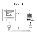
- FIG. 1 shows an example of a connecting state of each apparatus which can be commonly applied to the first and second embodiments of the invention.
- An SCSI board (not shown) is installed in a host computer 1.
- An SCSI cable 2 is connected to the SCSI board.
- the host computer 1 and a tape streamer 3 to which an embodiment of the invention is applied are connected by the SCSI cable 2.
- the tape streamer 3 has a CPU and a memory and executes a recording/reproduction of data on the basis of the control of the CPU by using a magnetic tape enclosed in a cassette as a recording medium.
- the SCSI board has, for example, a CPU and issues an SCSI command on the basis of an instruction generated from the host computer 1.
- a control of various phases of a data transfer by instructions of the host computer 1 is executed.
- Communication based on the SCSI command is made with a destination side (in this case, the tape streamer 3) via the SCSI cable 2 and data is transferred between the host computer 1 and tape streamer 3.
- Figs. 2A and 2B show examples of a data image on a magnetic tape in the tape streamer 3 which can be commonly applied to the first and second embodiments of the invention.
- data is written onto the tape on a file unit basis.
- a mark TM as a delimiter code of a file is written at the end of each file.
- a new file is written after the mark TM.
- each file comprises one or a plurality of blocks. As for the sizes of the blocks, there is a case where they are different as shown in Fig. 2B and there is also a case where all of them are equalized.
- a management table to manage the data written on the tape is provided at the head of the whole tape.
- a layout of the files or the like on the tape can be referred by reading the management table.
- the tape streamer 3 executes the recording to the magnetic tape by a helical scan system. Therefore, helical tracks are formed on the magnetic tape.
- a track set is formed by four tracks.
- the writing of data to the magnetic tape is executed on a track set unit basis.
- An ID to discriminate the track sets from one another is added to each track set.
- an area of sub-code data is arranged on the head side of an area in which a data main body is stored and an ID is written.
- a block management table to manage a block construction of the data main body is arranged on the end side of the area in which the data main body is stored.
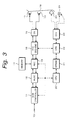
- Fig. 3 schematically shows an example of a construction of the tape streamer 3 which can be commonly applied to the first, second, third, and fourth embodiments of the invention.
- the SCSI cable 2 is connected to an input terminal 10.
- data transferred from the host computer 1 is supplied from the terminal 10 to an SCSI controller 11.
- SCSI controller 11 the SCSI command supplied from the terminal 10 is analyzed or executed and the data main body which is transferred and data associated to it are separated.
- the separated data main body is inputted to a data compressing controller ALDC 12 and is compression encoded by a predetermined method and the resultant data is supplied to an address controller ADC 13.
- the address controller AD 13 executes an address control to a memory 14 and controls the writing and reading operations of the data in the memory 14. For instance, for the memory 14, an address to start an access is designated as a pointer and a size of data which is accessed is also designated by the address controller ADC 13.
- the data is stored into the memory 14 as images on a magnetic tape 18 on the basis of the control of the address controller ADC 13.
- the data is read out from the memory 14 in correspondence to a writing timing on the basis of the control of the address controller 13 and is supplied to an ECC encoder/decoder 15.
- the ECC encoder/decoder 15 is constructed so as to function as an encoder when data is written and to function as a decoder upon reading.
- the supplied data is error correction encoded by a product code using, for example, a Reed Solomon code.
- the error correction encoded data is supplied to an equalizer 16.
- the data supplied to the equalizer 16 is converted to a signal suitable for recording to a recording medium and the resultant data is written and recorded as helical tracks onto the magnetic tape 18 by a recording head 17 as a rotary head. In this example, four tracks are recorded as one track set.
- the SCSI controller 11, data compressing controller ALDC 12, address controller ADC 13, and equalizer 16 are constructed so as to cope with both of the writing and recording operations in a manner similar to the ECC encoder/decoder 15.
- the signal read out from the magnetic tape 18 by a reproducing head 19 as a rotary head is supplied to the ECC encoder/decoder 15 via the equalizer 16.
- An error correction is performed to the data by the ECC encoder/decoder 15.
- the resultant data is written into the memory 14 by the control of the address controller ADC 13.
- the data written in the memory 14 is read out at a predetermined timing by the control of the address controller ADC 13 and is supplied to the data compressing controller ALDC 12.
- a compression encoding of the data is released and the resultant data is supplied to the SCSI controller 11.
- the data is transferred from the terminal 10 to the host computer 1 via the SCSI cable 2 by the control of the SCSI controller 11.
- the tape streamer 3 has three CPUs 20, 22, and 23.
- the CPU 20 controls the SCSI controller 11, data compressing controller 12, and address controller ADC 13.
- the data associated to the main body data and separated from the supplied main body data by the SCSI controller 11 is supplied to the CPU 20.
- the data and command are transmitted and received between the SCSI controller 11 and an SCSI board on the host computer 1 side by the SCSI controller 11.
- the CPU 22 controls the ECC encoder/decoder 15. A processing result of the ECC encoder/decoder 15 is supplied to the CPU 22.
- the CPU 23 controls the rotation of a motor 25 by a signal of the tracks formed in the longitudinal direction of the magnetic tape 18 and read out by a fixed head 24, a sense signal of the rotation of the motor 25 to drive the magnetic tape 18, and the like.
- a DPRAM 21 which is connected between the CPU 20 and CPU 22 is a dual port RAM and executes communication between the CPU 20 and CPU 22.
- the CPU 22 and CPU 23 can also similarly communicate.
- three CPUs 20, 22, and 23 are used here as CPUs, the invention is not limited to this arrangement, but can, for example, be also constructed by one CPU as a whole or can be also constructed by combining specific two CPUs.
- Fig. 4 shows a portion from the terminal 10 to the memory 14 in the construction in Fig. 3 in more detail.
- each of the SCSI controller 11, data compressing controller 12, and address controller 13 has an FIFO. That is, the SCSI controller 11 has an FIFO 111 on the side opposite to the terminal 10.
- the data compressing controller 12 has FIFOs 121 and 122 on both sides.
- the address controller 13 has an FIFO 131 on the side opposite to the memory 14.
- An FIFO 112 in which the writing and reading timings are controlled by the CPU 20 is further provided between the SCSI controller 11 and data compressing controller 12.
- Fig. 5 schematically shows the construction of Fig. 3 around the data structure in the memory 14 as a center.
- data is stored as writing images to the magnetic tape 18 into the memory 14.
- the writing to the magnetic tape 18 is executed on the unit basis of the track set comprising four tracks as mentioned above.
- addresses are provided by using the track set as a unit and data is written. Data of a plurality of blocks can be included in one track set.
- the data is arranged in the memory 14 so that an addressing can be performed every track set. For example, as shown in Fig. 5, one track set is arranged to one row of the addresses in the memory 14. The data is read out from the memory 14 every track set and the data of four tracks is written onto the magnetic tape 18.
- a WRITE command to instruct the tape streamer 3 to write data is transmitted from the host computer 1 through the SCSI board.
- a block table is formed in the host computer 1 and is transferred to the tape streamer 3 via the SCSI board.
- the reading of the data from the tape streamer 3 is also executed by using a READ command by a similar process. That is, the READ command is transmitted from the host computer 1 to the tape streamer 3. In the tape streamer 3, the data is read out from the tape on the basis of the command and a block table is formed on the basis of this read data. After the block data was transferred, the block table is transferred.
- Those processes in the host computer 1 are located between, for example, the OS (Operation System) and an application and are executed by a device driver for performing a management or the like of peripheral equipment which are connected to the host computer 1. Therefore, on the application side, the processes of embodiments of the invention can be realized by processes similar to the ordinary file writing and reading operations without being aware of those processes.
- the invention is not limited to them but, for example, the processes can be also directly executed in the application.
- Fig. 6 shows an example of a structure of the WRITE command and a READ command, which will be explained hereinlater.
- the command is constructed by six bytes and the first byte is set to an operation code.
- the kind of command is discriminated by a value which is stored in the operation code.
- the WRITE command is shown by "0Ah" (h denotes a hexadecimal notation).
- the READ command is shown by "08h”.
- Various parameters such as a logic unit number and the like are stored into the next byte.
- Subsequent three bytes show a size (total transfer length) of data to be transferred.
- Last one byte shows a control code.
- the WRITE/READ commands are also commonly used with respect to the first and second embodiments.
- the blocks of different sizes can be collectively transferred.
- a block table in which each block size or the like has been written is added to a plurality of blocks which are collectively transferred at once.
- Fig. 7 shows an example of the block table which is formed upon writing.
- the number (N) of blocks to be transferred to the first four bytes is stored into the block table upon writing and lengths of blocks are sequentially stored every four bytes in accordance with the transferring order of the blocks.
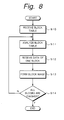
- Fig. 8 is a flowchart schematically showing processes upon recording of the data to the tape streamer 3.
- the transferred block table is received to the tape streamer 3 (step S10).
- the received block table is analyzed (step S11) and, after that, the data as much as the first one block is received (step S12).
- step S13 a block image is formed.
- the data is written to the magnetic tape by the formed block image.
- the processing routine is returned to step S11 and the processes of the next one block are executed.
- step S14 the apparatus waits for the reception of, for instance, the next block table.
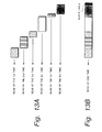
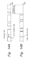
- Figs. 9A and 9B show states of data transfer which is executed as mentioned above in comparison with the conventional method.
- Fig. 9A shows an example in which a plurality of data blocks of different sizes are transferred and written by the conventional method. Hitherto, it is necessary to issue the WRITE command every block of a different size as mentioned above.
- the WRITE command is sent only once and, after that, the block table is transferred. On the basis of the block table, the data blocks are transferred one by one.
- the time that is required to transfer the data can be remarkably reduced rather than that by the conventional method of issuing the WRITE command every block.
- an overhead time is required for each command which is issued every block. That is, a predetermined overhead time is expended for a period of time from the transfer of one block to the transfer of the next block.
- the block table is transferred by the first one WRITE command and the blocks are continuously transferred in accordance with the contents of the block table. Therefore, as shown in an example in Fig. 10B, an analyzing time of the block table is merely expended for a period of time of transfer of each block. Even in case of transferring the same block as that in the example of Fig. 10A, consequently, the transfer time is extremely reduced.
- Fig. 11 is a flowchart schematically showing processes upon reading of the data from the tape streamer 3.
- the READ command to instruct the tape streamer 3 to read out the data is sent from the host computer 1 through the SCSI board.
- the data on the magnetic tape is read out on the basis of the received READ command.
- the read-out data is once stored into the memory and the block of the data is analyzed (step S20).
- step S21 only one block among the analyzed blocks is transferred to the SCSI board of the host computer 1.
- a block table regarding the transferred data block is formed in the memory (step S22).
- Fig. 12 shows an example of the block table which is formed upon reading.
- the lengths of blocks are sequentially stored every four bytes from the head of the table in accordance with the transferring order of the blocks. That is, the length data of the blocks which were read and transferred is sequentially stacked.
- the number (N) of blocks to be transferred is subsequently expressed by four bytes and stored.
- steps S20 to S22 are repeated until all of the data instructed by the READ command is transferred.
- step S23 the block table including all of the block information of the transferred data formed in step S22 is transferred from the tape streamer 3 to the SCSI board of the host computer 1 (step S24).
- Figs. 13A and 13B show states of data transfer which is executed as mentioned above in comparison with the conventional method.
- Fig. 13A shows an example in which a plurality of data blocks of different sizes are read and transferred by the conventional method.
- the block sizes are different, hitherto, only one data block can be read out by one READ command as mentioned above.
- a plurality of data blocks are transferred by one READ command and, after that, the block table is transferred.
- a data structure can be analyzed with reference to the transferred block table.
- the time that is required for data transfer can be remarkably reduced as compared with that by the conventional method of issuing the READ command every block.
- the overhead time is required for each command that is issued every block. That is, a predetermined overhead time is expended for a period of time from the transfer of one block to the transfer of the next block.
- the blocks are continuously transferred by the first one READ command, and the block table in which the information of each block is stored is finally transferred. Therefore, as shown in an example in Fig. 14B, the analyzing time of the block table is merely expended for each block transfer period of time. Therefore, even in case of transferring the same blocks as the example of Fig. 14A, the transfer time is remarkably reduced.
- the block table has a size that is extremely smaller than that of the data main body which is transferred and the block analysis is performed by a simple calculation in the CPU, so that the time which is required for block analysis can be ignored for the transfer time of the data.
- the time that is expended by the overhead according to the conventional method is long because it includes the time which is required for a control of the bus or the like and the like.
- the transfer time according to an embodiment of the invention has a superiority.
- Fig. 15 shows an example of a structure of transfer data according to the second embodiment. It is now assumed that N blocks are collectively transferred. A length of block which is transferred for the first time is stored into head four bytes. Subsequently, the data main body of the first block is stored. The end of block is filled with "0" and a zero-padding is executed so as to complete the block on a 4-byte unit basis.
- a set comprising the data of the block length and the data (and zero-padding) of the block main body is repeated by only the number of blocks to be transferred.
- N blocks are transferred
- such a set is repeated until the data main body of the Nth block is stored.
- the number (N) of transfer blocks is stored into the last four bytes.
- Fig. 16 is a flowchart showing a data writing process in the tape streamer 3 according to the second embodiment based on such a data structure.
- data to be written into the tape streamer 3 is prepared as a file and, for instance, a copy of the file to the tape streamer 3 is instructed.
- the WRITE command is issued from the host computer 1.
- the issued WRITE command is transferred to the SCSI controller 11 of the tape streamer 3 through the SCSI cable 2 and is sent from the SCSI controller 11 to the CPU 20.
- first step S30 a transfer command of data as much as four bytes is issued from the CPU 20 to the SCSI controller 11.
- the data of four bytes is block size data showing a size of block to be transferred. This data is stored into the built-in FIFO 111 of the SCSI controller 11.
- step S31 when a transfer end notification is issued from the SCSI controller 11 to the CPU 20, the block size data stored in the FIFO 111 is derived by the CPU 20 in next step S32.
- step S33 an additional data length is added to the obtained block data size, thereby setting a transfer length indicative of the length of data which is transferred.
- the additional data length is constructed by a padding size as a size of zero-padding and four bytes of the next block size data.
- the transfer length is set into the built-in FIFO 111 of the SCSI controller 11.
- next step S34 a start address of the block (assumes #n) to be transferred on the memory 14 and a transfer length to the delimiter of the block #n are set into the address controller ADC 13 by the CPU 20.
- a transfer start command is issued from the CPU 20.
- the start address for example, assuming that the block #n is a block which is first transferred, a predetermined address in the memory is set to the start address.
- the start address is obtained on the basis of the address of the previous transferred block.
- the transfer length to the delimiter of the block #n is obtained from, for example, the transfer length derived in step S33.
- the transfer of the block #n is started by the transfer start command issued from the CPU 20 and the data of the block #n is transferred from the host computer 1 to the tape streamer 3 through the SCSI cable 2.
- the transferred data is stored into a predetermined address in the memory 14 through the SCSI controller 11, data compressing controller ALDC 12, and address controller ADC 13.
- step S35 When a message indicative of the completion of the transfer of the block #n is notified from the address controller ADC 13 to the CPU 20 (step S35), an address in which the block subsequent to the block #n is started on the memory 14 and a padding data length of the transfer length up to the end of the block #n are set into the address controller ADC 13 by the CPU 20 in step S36.
- a transfer start command is issued from the CPU 20.
- step S37 When the message indicative of the completion of the transfer of the block #n is notified from the address controller ADC 13 to the CPU 20 (step S37), an address where the next block #(n+1) is written on the memory 14 is obtained by the CPU 20 in step S38. In next step S39, the address obtained in step S38 and 4 bytes corresponding to the block size data are set into the address controller ADC 13. The transfer start command is issued from the CPU 20. Thus, the block size data is written into the memory 14.
- step S40 When a message indicative of the completion of the transfer of the block #(n+1) is notified from the address controller ADD 13 to the CPU 20 (step S40), the block size data written in the memory 14 is read out in next step S41 and a block size of block to be subsequently transferred is obtained. A pointer in the memory 14 of an amount as much as the block size data (4 bytes) is returned by the CPU 20 (step S42). Thus, the next block is written in the memory 14 subsequently to the block written just before.
- next step S43 a check is made to see if all of the transferring processes by the WRITE command have been finished.
- the size of data to be transferred namely, a total transfer length is written in the WRITE command.
- the total number (N) of blocks which are transferred has been stored at the end of the data. The above discrimination is made by using the total transfer length and the total number (N) of blocks as transfer end conditions. If there is a block which is not yet transferred, the processing routine is returned to step S34.
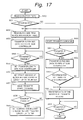
- Fig. 17 is a flowchart showing a data reading process in the tape streamer 3.
- information of the loaded tape is requested from the host computer 1 to the tape streamer 3.
- a management table at the head of the tape is read and information of a file written on the tape is transferred to the host computer 1.
- the READ command to designate the data to be read out from the tape streamer 3 is issued.
- the READ command is transferred to the SCSI controller 11 of the tape streamer 3 through the SCSI cable 2 and is sent from the SCSI controller 11 to the CPU 20.
- step S50 the data is read out from the magnetic tape 18 by the control of the CPU 20 based on the READ command.
- the read-out data is supplied to the ECC encoder/decoder 15 through the equalizer 16 and an error correcting process is executed by a predetermined method.
- the processing routine is jumped to step S64, which will be explained hereinlater (step S51).
- step S64 for example, the number of transferred blocks is set to "0" and the processes are finished.
- step S51 When there is no error in step S51, the error corrected data is written from a predetermined address in the memory 14 by a recording image on the tape through the address controller ADC 13.
- step S52 the block management table is read out from the memory 14 by the CPU 20 and the block size of the block to be transferred is obtained.
- the block size data indicative of the block size is transferred to the FIFO 111 built in the SCSI controller 11 (step S53).
- the transferred block size is set as a transfer length into the register of the SCSI controller 11 by the CPU 20 in step S55.
- next step S56 a start address of the block #n as a transfer block written in the memory 14 and the transfer length to the delimiter of the block #n are set into the address controller ADC 13 by the CPU 20.
- step S57 the transfer start command is issued from the CPU 20 to the address controller ADC 13.
- the data of an amount corresponding to only the length designated by the transfer length is read out from the start address of the block #n in the memory 14.
- the read-out data is supplied to the SCSI controller 11 through the address controller ADC 13 and data compressing controller ALDC 12.
- the SCSI controller 11 a control and the like of the SCSI bus are executed and the block #n is transferred from the terminal 10 to the host computer 1 through the SCSI cable 2.
- step S58 When the transfer is finished (step S58), in next step S59, an address where the block next to the block #n starts in the memory 14 is set into the address controller ADC 13 by the CPU 20 and the length to the end of the block #n is set as a transfer length. In step S60, the transfer start command is issued and the transfer is started.
- step S61 the processing routine advances to step S62 and the padding data is transferred to the built-in FIFO 111 of the SCSI controller 11 by the CPU 20.
- next step S63 a check is made to see if all of the transferring processes by the READ command have been finished.
- the size of data to be transferred namely, the total transfer length has been written in the READ command.
- the total number (N) of blocks to be transferred has been stored at the end of the data. This discrimination is made by using the total transfer length and the total number (N) of blocks as transfer end conditions. If there is a block which is not yet transferred, the processing routine is returned to step S52.
- step S63 When it is determined in step S63 that the transfer has been finished, the processing routine advances to step S64.
- the number (N) of transferred blocks is transferred to the built-in FIFO 111 of the SCSI controller 11 by the CPU 20.
- a series of processes is finished after waiting for the end of the transfer in step S65.
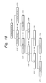
- FIG. 18 shows relations among the block, file, set (directory), volume, physical device, and storage system.
- a storage system 200 has one or more physical devices 210.
- the physical device is a hard disk, a floppy disk, an optical disk, or the like.
- Each physical device 210 has one or more volumes 220.
- Each volume 220 has one or more sets 230.
- each set 230 has one or more files 240.
- each file 240 has one or more blocks 250.
- the block, file, set, volume, physical device, and storage system mutually have hierarchy relations.
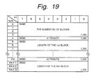
- Fig. 19 shows an example of a block table which is formed when writing according to the third embodiment of the invention. As shown in Fig. 19, the number (N) of blocks to be transferred is shown by the first four bytes.
- the data showing the attribute consists of 8 bits and a file mark, a set mark, a volume mark, and a physical device mark are shown by a value of such data.
- a boundary of the file, set, volume, or physical device namely, a delimiter is located at the position of the ith block
- the data showing the length of the ith block is set to [0] and which one of the boundaries of the file, set, volume, and physical device such a boundary indicates is shown by the data of 1 byte indicative of the attribute.
- the value of the attribute data of 8 bits when the value of the attribute data of 8 bits is equal to [10000000], it shows the boundary of the file. When the value of the attribute data of 8 bits is equal to [01000000], it shows the boundary of the set. When the value of the attribute data of 8 bits is equal to [00100000], it shows the boundary of the volume. When the value of the attribute data of 8 bits is equal to [0010000], it shows the boundary of the physical device. Further, when the boundary is none of them, the value of the attribute data of 8 bits is set to [00000000].
- the data of one byte showing the attribute and the data showing the length of the ith block as many as only the number (N) of blocks are stored into the block table.
- each boundary of the block, file, set, volume, and physical device of each hierarchy can be identified upon reproduction.
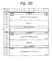
- Fig. 20 shows an example of the block table which is formed upon writing according to the fourth embodiment of the invention.
- the data main body of the ith block is stored after the data showing the length of the ith block.
- the end of the block main body is filled with the [0] data of the necessary number and the zero-padding is performed so as to complete the data main body on a 4-byte unit basis.
- the value of the attribute data of 8 bits when the value of the attribute data of 8 bits is equal to [10000000], it shows the boundary of the file. When the value of the attribute data of 8 bits is equal to [01000000], it shows the boundary of the set. When the value of the attribute data of 8 bits is equal to [00100000], it shows the boundary of the volume. When the value of the attribute data of 8 bits is equal to [00010000], it shows the boundary of the physical device. Further, when the boundary is none of them, the value of the attribute data of 8 bits is set to [00000000].
- the data of 1 byte showing the attribute, the data indicative of the length of the ith block, and the data main body as many as only the number (N) of blocks are stored into the block table.
- the data showing the number (N) of transfer blocks is stored into the last four bytes.
- each boundary of the block, file, set, volume, and physical device of each hierarchy can be identified upon reproduction.
- the data can be reproduced without using any special application software to reconstruct a plurality of files, sets, volumes, and physical devices which were combined in one group.
- the technique of preferred embodiments is applied to the protocol of the SCSI
- the technique is not limited to such an example.
- the technique can be also applied to a data transfer protocol such as IPI-3 (Intelligent Peripheral Interface) or the like.
- the technique is also suitable for use in another protocol such that the overhead between commands is large.
- the data transferred by the method according to embodiments of the invention can be also read and written even by an existing device driver because, for instance, the format when the data is written to the tape streamer 3 is similar to the conventional one.
- the structure of block is added to the data in a form of the block table, there is an effect such that after the block table was first transferred to the host computer, the block structure can be analyzed.
Applications Claiming Priority (4)
| Application Number | Priority Date | Filing Date | Title |
|---|---|---|---|
| JP3466998 | 1998-02-17 | ||
| JP3466998 | 1998-02-17 | ||
| JP23073898A JP4324993B2 (ja) | 1998-02-17 | 1998-08-17 | データ転送方法および装置 |
| JP23073898 | 1998-08-17 |
Publications (2)
| Publication Number | Publication Date |
|---|---|
| EP0936561A2 true EP0936561A2 (fr) | 1999-08-18 |
| EP0936561A3 EP0936561A3 (fr) | 2003-10-15 |
Family
ID=26373504
Family Applications (1)
| Application Number | Title | Priority Date | Filing Date |
|---|---|---|---|
| EP99301070A Withdrawn EP0936561A3 (fr) | 1998-02-17 | 1999-02-15 | Méthode et dispositif de transmission de données sur un bus SCSI |
Country Status (5)
| Country | Link |
|---|---|
| US (1) | US6349348B1 (fr) |
| EP (1) | EP0936561A3 (fr) |
| JP (1) | JP4324993B2 (fr) |
| KR (1) | KR100659915B1 (fr) |
| CN (1) | CN1154941C (fr) |
Families Citing this family (8)
| Publication number | Priority date | Publication date | Assignee | Title |
|---|---|---|---|---|
| DE10216921A1 (de) * | 2002-04-15 | 2003-10-23 | Bosch Gmbh Robert | Verfahren und Vorrichtung zum Auffüllen von Datenabschnitten sowie Bussystem |
| US6907478B2 (en) * | 2003-02-18 | 2005-06-14 | Adaptec, Inc. | Systems and methods optimizing data transfer throughput of a system on chip |
| US7496492B2 (en) * | 2003-08-29 | 2009-02-24 | Microsoft Corporation | Software-aided storage device emulation in a physical storage device |
| CN100358320C (zh) * | 2003-12-24 | 2007-12-26 | 华为技术有限公司 | 一种数据包存储的管理方法和装置 |
| JP4679234B2 (ja) * | 2005-05-19 | 2011-04-27 | Hoya株式会社 | 動画記録装置 |
| JP4286858B2 (ja) | 2006-11-06 | 2009-07-01 | シャープ株式会社 | 測定データ通信装置、情報取得装置、およびシステム |
| US8908314B2 (en) * | 2011-08-19 | 2014-12-09 | Oracle International Corporation | Data file information based selection of tape drive tape speed |
| JP5172005B2 (ja) * | 2011-10-17 | 2013-03-27 | 京セラ株式会社 | 情報処理装置、転送データ数表示方法、及び転送データ数表示プログラム |
Citations (4)
| Publication number | Priority date | Publication date | Assignee | Title |
|---|---|---|---|---|
| EP0540316A2 (fr) * | 1991-10-30 | 1993-05-05 | International Business Machines Corporation | Procédé de codage |
| US5335328A (en) * | 1989-06-28 | 1994-08-02 | International Business Machines Corporation | Methods for recording and reading data from a record member having data in any one of a plurality of block formats including determining length of records being transferred |
| US5410546A (en) * | 1993-11-01 | 1995-04-25 | Storage Technology Corporation | Apparatus and method for CRC computation over fixed length blocks containing variable length packets of data received out of order |
| GB2285525A (en) * | 1994-01-11 | 1995-07-12 | Dascom Software Dev Services L | A tape database control process |
Family Cites Families (14)
| Publication number | Priority date | Publication date | Assignee | Title |
|---|---|---|---|---|
| US4525837A (en) * | 1982-07-07 | 1985-06-25 | Fuji Xerox Co., Ltd. | Digital signal transmission system |
| JP3134424B2 (ja) * | 1991-10-31 | 2001-02-13 | ソニー株式会社 | 可変長符号化方法及び装置 |
| US5647057A (en) * | 1992-08-24 | 1997-07-08 | Texas Instruments Incorporated | Multiple block transfer mechanism |
| JP3446237B2 (ja) * | 1993-04-16 | 2003-09-16 | ソニー株式会社 | 可変長符号テーブル生成方法及び装置 |
| JPH07191899A (ja) * | 1993-12-27 | 1995-07-28 | Hitachi Ltd | ファイル転送方法、データアクセス方法およびデータ書き込み方法 |
| US5581790A (en) * | 1994-06-07 | 1996-12-03 | Unisys Corporation | Data feeder control system for performing data integrity check while transferring predetermined number of blocks with variable bytes through a selected one of many channels |
| US5841598A (en) * | 1994-10-28 | 1998-11-24 | Olympus Optical Co., Ltd. | Information recording/reproducing apparatus and data processing method |
| JP3720439B2 (ja) * | 1995-01-06 | 2005-11-30 | キヤノン株式会社 | データ入出力制御装置及びデータ入出力制御方法 |
| KR100235123B1 (ko) * | 1995-02-24 | 1999-12-15 | 이데이 노부유끼 | 테이프 스트리머를 사용한 디지털 데이터의 복사장치 |
| JPH0982039A (ja) * | 1995-09-18 | 1997-03-28 | Sony Corp | 情報記録方法および追記型光ディスク記録方法 |
| EP0767575B1 (fr) * | 1995-10-04 | 2004-01-02 | Canon Kabushiki Kaisha | Appareil et système balayeur-serveur |
| JPH09261232A (ja) * | 1996-03-19 | 1997-10-03 | Fujitsu Ltd | Atm交換機における複数応答通信制御方法 |
| EP0845738A3 (fr) * | 1996-11-28 | 2006-09-20 | Hitachi, Ltd. | Système de stockage pour transférer une commande et transférer des données correspondant à cette commande, après cette commande |
| US6160778A (en) * | 1999-03-08 | 2000-12-12 | Matsushita Electric Industrial Co., Ltd. | Information recording medium, information recording method, information recording apparatus and information reproducing apparatus |
-
1998
- 1998-08-17 JP JP23073898A patent/JP4324993B2/ja not_active Expired - Fee Related
-
1999
- 1999-02-11 KR KR1019990004793A patent/KR100659915B1/ko not_active IP Right Cessation
- 1999-02-14 CN CNB991055179A patent/CN1154941C/zh not_active Expired - Fee Related
- 1999-02-15 EP EP99301070A patent/EP0936561A3/fr not_active Withdrawn
- 1999-02-16 US US09/251,123 patent/US6349348B1/en not_active Expired - Fee Related
Patent Citations (4)
| Publication number | Priority date | Publication date | Assignee | Title |
|---|---|---|---|---|
| US5335328A (en) * | 1989-06-28 | 1994-08-02 | International Business Machines Corporation | Methods for recording and reading data from a record member having data in any one of a plurality of block formats including determining length of records being transferred |
| EP0540316A2 (fr) * | 1991-10-30 | 1993-05-05 | International Business Machines Corporation | Procédé de codage |
| US5410546A (en) * | 1993-11-01 | 1995-04-25 | Storage Technology Corporation | Apparatus and method for CRC computation over fixed length blocks containing variable length packets of data received out of order |
| GB2285525A (en) * | 1994-01-11 | 1995-07-12 | Dascom Software Dev Services L | A tape database control process |
Also Published As
| Publication number | Publication date |
|---|---|
| CN1154941C (zh) | 2004-06-23 |
| KR100659915B1 (ko) | 2006-12-21 |
| JP4324993B2 (ja) | 2009-09-02 |
| CN1234563A (zh) | 1999-11-10 |
| EP0936561A3 (fr) | 2003-10-15 |
| KR19990072581A (ko) | 1999-09-27 |
| US6349348B1 (en) | 2002-02-19 |
| JPH11306124A (ja) | 1999-11-05 |
Similar Documents
| Publication | Publication Date | Title |
|---|---|---|
| US7346754B2 (en) | Control method for storage device controller system, and storage device controller system | |
| US6324604B1 (en) | Magnetic disk storage for storing data in disk block size from fixed length of host block in non-integer multiple of the disk block size | |
| JP3763845B2 (ja) | 固定ブロック内における可変長レコードのパッキング | |
| JP3245364B2 (ja) | 互いに異なるインタフェースを介して記憶装置を共用する方法及びシステム | |
| US5384669A (en) | Combining small records into a single record block for recording on a record media | |
| US6724982B1 (en) | Digital audiovisual magnetic disk doubly linked list recording format extension to multiple devices | |
| US5274772A (en) | Data processing systems having means for selectively combining records into signal blocks for recording in a record medium | |
| EP1805589B1 (fr) | Memoire basee sur un disque d'emulation de bande et procede de redimensionnement automatique de la capacite de bande emulee | |
| US5537552A (en) | Apparatus for selectively comparing pointers to detect full or empty status of a circular buffer area in an input/output (I/O) buffer | |
| US6718410B2 (en) | System for transferring data in a CD image format size of a host computer and storing the data to a tape medium in a format compatible with streaming | |
| US6292878B1 (en) | Data recorder and method of access to data recorder | |
| US5887128A (en) | Method and apparatus for redundant disk storage system with offset | |
| US5774287A (en) | System and method employing buffering mechanism with interface for providing compatibility between recording formats | |
| US5535327A (en) | Method and apparatus for communicating formatted data from a mass storage device to a host computer | |
| US5461719A (en) | Method for recording/reproducing information on recording medium in accordance with parameters stored in memory to allow sectors of different data capacities to collectively exist | |
| EP0844566B1 (fr) | Dispositif d'interface pour adapter la largeur de données à la largeur du bus système | |
| US6349348B1 (en) | Data transfer method and apparatus | |
| KR20010107509A (ko) | 재생 오류의 처리 방법 및 이를 이용한 디스크 장치 | |
| US6161155A (en) | Apparatus and method for storing retrievable boundary information into a buffer memory of a receiving device | |
| EP1110219A1 (fr) | Procede ameliore permettant l'operation de formatage de secteur variable dans un systeme informatique | |
| JP4422319B2 (ja) | 多重化記憶制御装置 | |
| JPH0541037A (ja) | デイジタルデータ記録再生装置 | |
| JP2002135270A (ja) | データの非同期転送方式 | |
| JP2001125746A (ja) | データ記録/再生システム、データ記録/再生装置及びデータ記録/再生方法 |
Legal Events
| Date | Code | Title | Description |
|---|---|---|---|
| PUAI | Public reference made under article 153(3) epc to a published international application that has entered the european phase |
Free format text: ORIGINAL CODE: 0009012 |
|
| AK | Designated contracting states |
Kind code of ref document: A2 Designated state(s): AT BE CH CY DE DK ES FI FR GB GR IE IT LI LU MC NL PT SE |
|
| AX | Request for extension of the european patent |
Free format text: AL;LT;LV;MK;RO;SI |
|
| PUAL | Search report despatched |
Free format text: ORIGINAL CODE: 0009013 |
|
| AK | Designated contracting states |
Kind code of ref document: A3 Designated state(s): AT BE CH CY DE DK ES FI FR GB GR IE IT LI LU MC NL PT SE |
|
| AX | Request for extension of the european patent |
Extension state: AL LT LV MK RO SI |
|
| 17P | Request for examination filed |
Effective date: 20040330 |
|
| AKX | Designation fees paid |
Designated state(s): DE FR GB |
|
| 17Q | First examination report despatched |
Effective date: 20060927 |
|
| GRAP | Despatch of communication of intention to grant a patent |
Free format text: ORIGINAL CODE: EPIDOSNIGR1 |
|
| STAA | Information on the status of an ep patent application or granted ep patent |
Free format text: STATUS: THE APPLICATION IS DEEMED TO BE WITHDRAWN |
|
| 18D | Application deemed to be withdrawn |
Effective date: 20090804 |