EP0936463B1 - Gas sensor element and method for manufacturing the element - Google Patents
Gas sensor element and method for manufacturing the element Download PDFInfo
- Publication number
- EP0936463B1 EP0936463B1 EP99300991A EP99300991A EP0936463B1 EP 0936463 B1 EP0936463 B1 EP 0936463B1 EP 99300991 A EP99300991 A EP 99300991A EP 99300991 A EP99300991 A EP 99300991A EP 0936463 B1 EP0936463 B1 EP 0936463B1
- Authority
- EP
- European Patent Office
- Prior art keywords
- base body
- paste
- gas sensor
- sensor element
- projections
- Prior art date
- Legal status (The legal status is an assumption and is not a legal conclusion. Google has not performed a legal analysis and makes no representation as to the accuracy of the status listed.)
- Expired - Lifetime
Links
- 238000000034 method Methods 0.000 title claims description 31
- 238000004519 manufacturing process Methods 0.000 title claims description 22
- 239000008187 granular material Substances 0.000 claims description 34
- 239000002245 particle Substances 0.000 claims description 33
- 239000007784 solid electrolyte Substances 0.000 claims description 31
- 239000000463 material Substances 0.000 claims description 14
- 238000007788 roughening Methods 0.000 claims description 10
- 238000010304 firing Methods 0.000 claims description 9
- 239000000203 mixture Substances 0.000 claims description 9
- 238000002156 mixing Methods 0.000 claims description 6
- 239000010410 layer Substances 0.000 description 57
- 239000007789 gas Substances 0.000 description 36
- MCMNRKCIXSYSNV-UHFFFAOYSA-N Zirconium dioxide Chemical compound O=[Zr]=O MCMNRKCIXSYSNV-UHFFFAOYSA-N 0.000 description 24
- 239000011148 porous material Substances 0.000 description 19
- XLYOFNOQVPJJNP-UHFFFAOYSA-N water Chemical compound O XLYOFNOQVPJJNP-UHFFFAOYSA-N 0.000 description 18
- 229910052596 spinel Inorganic materials 0.000 description 16
- 239000011029 spinel Substances 0.000 description 16
- 230000015572 biosynthetic process Effects 0.000 description 12
- 239000011248 coating agent Substances 0.000 description 9
- 238000000576 coating method Methods 0.000 description 9
- 239000011230 binding agent Substances 0.000 description 8
- BASFCYQUMIYNBI-UHFFFAOYSA-N platinum Chemical compound [Pt] BASFCYQUMIYNBI-UHFFFAOYSA-N 0.000 description 8
- QVGXLLKOCUKJST-UHFFFAOYSA-N atomic oxygen Chemical compound [O] QVGXLLKOCUKJST-UHFFFAOYSA-N 0.000 description 6
- 239000001301 oxygen Substances 0.000 description 6
- 229910052760 oxygen Inorganic materials 0.000 description 6
- 239000000843 powder Substances 0.000 description 6
- 230000002950 deficient Effects 0.000 description 5
- 239000007921 spray Substances 0.000 description 5
- 230000007704 transition Effects 0.000 description 5
- 239000010419 fine particle Substances 0.000 description 4
- 229910052751 metal Inorganic materials 0.000 description 4
- 239000002184 metal Substances 0.000 description 4
- 229910052697 platinum Inorganic materials 0.000 description 4
- 230000002349 favourable effect Effects 0.000 description 3
- 238000005469 granulation Methods 0.000 description 3
- 230000003179 granulation Effects 0.000 description 3
- 239000012046 mixed solvent Substances 0.000 description 3
- 239000011241 protective layer Substances 0.000 description 3
- 230000000007 visual effect Effects 0.000 description 3
- KDLHZDBZIXYQEI-UHFFFAOYSA-N Palladium Chemical compound [Pd] KDLHZDBZIXYQEI-UHFFFAOYSA-N 0.000 description 2
- 239000004372 Polyvinyl alcohol Substances 0.000 description 2
- VYPSYNLAJGMNEJ-UHFFFAOYSA-N Silicium dioxide Chemical compound O=[Si]=O VYPSYNLAJGMNEJ-UHFFFAOYSA-N 0.000 description 2
- 230000003197 catalytic effect Effects 0.000 description 2
- 229920001971 elastomer Polymers 0.000 description 2
- 238000011156 evaluation Methods 0.000 description 2
- 230000001747 exhibiting effect Effects 0.000 description 2
- 230000001590 oxidative effect Effects 0.000 description 2
- 229910002077 partially stabilized zirconia Inorganic materials 0.000 description 2
- 229920002451 polyvinyl alcohol Polymers 0.000 description 2
- 239000002244 precipitate Substances 0.000 description 2
- 238000010298 pulverizing process Methods 0.000 description 2
- 239000011369 resultant mixture Substances 0.000 description 2
- 239000002356 single layer Substances 0.000 description 2
- 239000002002 slurry Substances 0.000 description 2
- 229910002076 stabilized zirconia Inorganic materials 0.000 description 2
- 229910000314 transition metal oxide Inorganic materials 0.000 description 2
- 244000171897 Acacia nilotica subsp nilotica Species 0.000 description 1
- QGZKDVFQNNGYKY-UHFFFAOYSA-O Ammonium Chemical compound [NH4+] QGZKDVFQNNGYKY-UHFFFAOYSA-O 0.000 description 1
- AEMRFAOFKBGASW-UHFFFAOYSA-M Glycolate Chemical compound OCC([O-])=O AEMRFAOFKBGASW-UHFFFAOYSA-M 0.000 description 1
- 229920000084 Gum arabic Polymers 0.000 description 1
- KJTLSVCANCCWHF-UHFFFAOYSA-N Ruthenium Chemical compound [Ru] KJTLSVCANCCWHF-UHFFFAOYSA-N 0.000 description 1
- 239000005862 Whey Substances 0.000 description 1
- 102000007544 Whey Proteins Human genes 0.000 description 1
- 108010046377 Whey Proteins Proteins 0.000 description 1
- 239000000205 acacia gum Substances 0.000 description 1
- 235000010489 acacia gum Nutrition 0.000 description 1
- DPXJVFZANSGRMM-UHFFFAOYSA-N acetic acid;2,3,4,5,6-pentahydroxyhexanal;sodium Chemical compound [Na].CC(O)=O.OCC(O)C(O)C(O)C(O)C=O DPXJVFZANSGRMM-UHFFFAOYSA-N 0.000 description 1
- 239000000956 alloy Substances 0.000 description 1
- 229910045601 alloy Inorganic materials 0.000 description 1
- PNEYBMLMFCGWSK-UHFFFAOYSA-N aluminium oxide Inorganic materials [O-2].[O-2].[O-2].[Al+3].[Al+3] PNEYBMLMFCGWSK-UHFFFAOYSA-N 0.000 description 1
- QZPSXPBJTPJTSZ-UHFFFAOYSA-N aqua regia Chemical compound Cl.O[N+]([O-])=O QZPSXPBJTPJTSZ-UHFFFAOYSA-N 0.000 description 1
- 239000003054 catalyst Substances 0.000 description 1
- 239000001913 cellulose Substances 0.000 description 1
- 229920002678 cellulose Polymers 0.000 description 1
- 238000005234 chemical deposition Methods 0.000 description 1
- 229910052681 coesite Inorganic materials 0.000 description 1
- 150000001875 compounds Chemical class 0.000 description 1
- 229910052593 corundum Inorganic materials 0.000 description 1
- 238000005336 cracking Methods 0.000 description 1
- 229910052906 cristobalite Inorganic materials 0.000 description 1
- 238000000354 decomposition reaction Methods 0.000 description 1
- 230000007423 decrease Effects 0.000 description 1
- 230000007547 defect Effects 0.000 description 1
- 230000006866 deterioration Effects 0.000 description 1
- 230000000694 effects Effects 0.000 description 1
- 238000007772 electroless plating Methods 0.000 description 1
- 238000009713 electroplating Methods 0.000 description 1
- 238000010438 heat treatment Methods 0.000 description 1
- 230000001771 impaired effect Effects 0.000 description 1
- JEIPFZHSYJVQDO-UHFFFAOYSA-N iron(III) oxide Inorganic materials O=[Fe]O[Fe]=O JEIPFZHSYJVQDO-UHFFFAOYSA-N 0.000 description 1
- 238000010030 laminating Methods 0.000 description 1
- 229910044991 metal oxide Inorganic materials 0.000 description 1
- 238000007254 oxidation reaction Methods 0.000 description 1
- SIWVEOZUMHYXCS-UHFFFAOYSA-N oxo(oxoyttriooxy)yttrium Chemical compound O=[Y]O[Y]=O SIWVEOZUMHYXCS-UHFFFAOYSA-N 0.000 description 1
- RVTZCBVAJQQJTK-UHFFFAOYSA-N oxygen(2-);zirconium(4+) Chemical compound [O-2].[O-2].[Zr+4] RVTZCBVAJQQJTK-UHFFFAOYSA-N 0.000 description 1
- 229910052763 palladium Inorganic materials 0.000 description 1
- 230000035515 penetration Effects 0.000 description 1
- 238000007747 plating Methods 0.000 description 1
- 238000002360 preparation method Methods 0.000 description 1
- 238000003825 pressing Methods 0.000 description 1
- 230000001105 regulatory effect Effects 0.000 description 1
- 229910052703 rhodium Inorganic materials 0.000 description 1
- 239000010948 rhodium Substances 0.000 description 1
- MHOVAHRLVXNVSD-UHFFFAOYSA-N rhodium atom Chemical compound [Rh] MHOVAHRLVXNVSD-UHFFFAOYSA-N 0.000 description 1
- 230000000630 rising effect Effects 0.000 description 1
- 229910052707 ruthenium Inorganic materials 0.000 description 1
- 150000003839 salts Chemical class 0.000 description 1
- 238000007873 sieving Methods 0.000 description 1
- 239000000377 silicon dioxide Substances 0.000 description 1
- 238000005245 sintering Methods 0.000 description 1
- 229910052682 stishovite Inorganic materials 0.000 description 1
- 239000002344 surface layer Substances 0.000 description 1
- 238000007751 thermal spraying Methods 0.000 description 1
- 229910052905 tridymite Inorganic materials 0.000 description 1
- 238000001771 vacuum deposition Methods 0.000 description 1
- 239000003232 water-soluble binding agent Substances 0.000 description 1
- 229910001845 yogo sapphire Inorganic materials 0.000 description 1
- 229910001928 zirconium oxide Inorganic materials 0.000 description 1
Images




Classifications
-
- G—PHYSICS
- G01—MEASURING; TESTING
- G01N—INVESTIGATING OR ANALYSING MATERIALS BY DETERMINING THEIR CHEMICAL OR PHYSICAL PROPERTIES
- G01N27/00—Investigating or analysing materials by the use of electric, electrochemical, or magnetic means
- G01N27/26—Investigating or analysing materials by the use of electric, electrochemical, or magnetic means by investigating electrochemical variables; by using electrolysis or electrophoresis
- G01N27/403—Cells and electrode assemblies
- G01N27/406—Cells and probes with solid electrolytes
- G01N27/407—Cells and probes with solid electrolytes for investigating or analysing gases
- G01N27/4077—Means for protecting the electrolyte or the electrodes
Definitions
- the present invention relates to a gas sensor element which includes a solid electrolyte layer having a plurality of projections on its outer surface, an inner electrode provided on the inner surface of the solid electrolyte layer, an outer electrode provided on the outer surface of the solid electrolyte layer, and a protection layer covering the outer electrode for protection of the outer electrode and in which an electrical characteristic value as measured between the electrodes varies according to a component of gas to be detected.
- the manufacturing method comprises the steps of: applying a mixture of granules and minute particles onto the surface of a zirconia base body; and firing the base body and the applied mixture simultaneously to thereby form a number of pits and projections on the surface of the base body.
- Japanese Patent Application Laid-Open ( kokai ) No. 56-160653 discloses a method for manufacturing a zirconia oxygen sensor element, including a step of applying a paste of mixed granules and minute particles onto a surface of a zirconia base body at a thickness of 40 ⁇ m to 300 ⁇ m through use of a brush.
- projections are formed on the surface of the base body through firing, and the surface is coated with an electrode.
- the electrode penetrates into pits formed between projections, thereby increasing its surface area and establishing a strong bond.
- 2-44391 discloses a method for manufacturing a zirconia oxygen sensor element, including a step of applying a similar paste onto a surface of a zirconia base body in an overflowing manner through use of a roller so as to form a surface layer having a final thickness of 100 ⁇ m.
- an oxygen concentration cell has often been required to be installed downstream of a three-way catalytic converter.
- the oxygen concentration cell must function properly in an environment having a temperature of 200°C to 300°C and that is rich with water vapor, in which zirconia is apt to undergo phase transition.
- the oxygen sensor elements described in Japanese Patent Application Laid-Open ( kokai ) No. 56-160653 and Japanese Patent Publication No. 2-44391 include portions where granules are present in layers, implying the formation of "pores" (a pore is a minute opening formed between neighboring projections as a result of bonding of tips of the projections or between layered projections).
- pores a pore is a minute opening formed between neighboring projections as a result of bonding of tips of the projections or between layered projections.
- water vapor enters the "pores," causing the phase transition of zirconia to extend to considerably deep portions of projections.
- the projections change in volume on a microscopic scale, causing the formation of minute cracks in the projections. Therefore, the projections may break away from the zirconia base body to cause a crack failure.
- US patent 5,443,711 relates to an oxygen-sensor element including a solid-electrolyte body. On the inner side of the body, there is provided a platinum electrode. On the outer side of the body spherical protruded particles are provided and on the surface of these particles a further platinum electrode is formed.
- a porous protective layer is formed on the surface of the detection-gas-side electrode, wherein at least a part of said porous protective layer is formed by a granular texture of a grain size of 0.1 to 0.5 ⁇ m formed mainly of a non-stoichiometric compound of a transition metal oxide (TiOx), and a catalyst for having gas components of the gas to be measured react is carried in at least a part of the porous protective layer. Oxidation reaction of gas components is improved to prevent deterioration of the responsive property.
- TiOx transition metal oxide
- an object of the present invention is to provide a method of manufacturing a gas sensor element exhibiting improved durability against high temperature and high humidity while maintaining strong bond between a solid electrolyte layer and an outer electrode and a strong bond between the outer electrode and a protection layer.
- a method for manufacturing a gas sensor element comprising the steps of: rotating a substantially cylindrical base body made of an unfired solid electrolyte material; applying a paste ⁇ which includes roughening particles of material substantially similar to that for the base body and has a viscosity of 500 CPS to 1600 CPS ⁇ onto the base body in such a manner that the paste is brought into contact with the base body and is moved in a direction opposite to a moving direction of the base body at a position of contact between the paste and the base body; and firing the base body coated with the paste to thereby form a plurality of projections on the base body.
- the solid electrolyte material may contain as a main component stabilized or partially stabilized zirconia, for example, and, as needed, Al 2 O 3 , SiO 2 , and Fe 2 O 3 .
- the base body may be prepared by the steps of: mixing ZrO 2 with a bivalent or trivalent metallic oxide, such as Y 2 O 3 , CaO, or MgO, in a desired proportion and pulverizing the resultant mixture; preliminarily firing the mixture in an electric furnace; pulverizing the preliminarily fired mixture to thereby obtain a material powder of stabilized or partially stabilized zirconia; and forming the material powder into a substantially cylindrical shape; for example, into a cylinder with one closed end, by way of a pressing method, such as a rubber press method, or by way of a laminating method, such as a thick-film method.
- the paste is a fluidized mixture, which includes roughening particles of material substantially similar to that for the base body.
- Material for the roughening particles is not necessarily identical to that for the base body, but must be basically identical in properties to that for the base body; otherwise, in the subsequent firing process, the base body and the roughening particles may not be integrated stably and reliably.
- the base body coated with the paste is dried and is then fired at a temperature of 1400°C to 1600°C for 1 to 3 hours, for example. An oxidizing atmosphere is usually preferred for firing.
- the base body having a plurality of projections formed thereon through firing serves as the solid electrolyte layer having a plurality of projections on its outer surface.
- An electrode is formed on each of the inner and outer surfaces of the solid electrolyte layer.
- a heat resistant, catalytic metal is used as material for the electrodes. Examples of such a metal include platinum, ruthenium, rhodium, palladium, and their alloys.
- the method for forming the electrodes include vacuum deposition, chemical deposition, electroless plating, electroplating, and a method composed of the steps of applying a decomposable metal salt onto the solid electrolyte layer and heating the coated solid electrolyte layer so as to deposit the metal through decomposition.
- the outer electrode is formed along the rugged surface of the solid electrolyte layer, thereby increasing the surface area of the electrode and improving adhesion of the electrode.
- the paste is moved in a direction opposite to a moving direction of the base body at the position of contact between the paste and the base body, thereby substantially uniformly applying the paste onto the outer surface of the rotating base body and thus substantially uniformly distributing roughening particles throughout the outer surface of the base body.
- This method for manufacturing a gas sensor element is suited for applying roughening particles in such a manner as to meet the following conditions: a plurality of projections are formed on a portion of or on the entirety of the region of the outer surface of the solid electrolyte layer that is covered with the protection layer; the plurality of projections are formed in a single layer; an area occupied by the projections accounts for 10% to 85% that of the portion of the outer surface of the solid electrolyte layer on which the projections are formed; and the distance between neighboring projections is 5 ⁇ m to 400 ⁇ m.
- the method is suited for manufacture of the gas sensor element according to the first aspect of the invention.
- the paste is fed onto the outer circumferential surface of a rotary drum rotating in the same direction as does the base body, such that the fed paste is present in a predetermined thickness on the drum.
- the paste and the base body can be moved in opposite directions at the position of contact between the paste and the base body.
- the axial rotational speed of the base body and the rotational speed of the rotary drum are regulated such that the base body is moved at a speed of 3.0 cm/sec to 24.0 cm/sec at the contact position and such that the paste is moved at a speed of 2.0 cm/sec to 8.0 cm/sec at the contact position.
- the base body is moved at a speed of less than 3.0 cm/sec, the amount of the paste adhering to the base body increases; consequently, "pores" are more apt to be formed. If the base body is moved at a speed in excess of 24.0 cm/sec, the friction between the base body and the roughening particles contained in the paste tends to initiate wear on the base body. If the paste is moved at a speed of less than 2.0 cm/sec, the paste present on the rotary drum tends to flow downward due to its own weight. If the paste is moved at a speed in excess of 8.0 cm/sec, the amount of the paste adhering to the base body increases; consequently, "pores" are more apt to be formed.
- the weight of the paste adhering to the base body is 5.0 mg/cm 2 to 18.0 mg/cm 2 . If the weight of the paste adhering to the base body is less than 5.0 mg/cm 2 , formation of a sufficient number of projections on the surface of the base body becomes difficult to achieve; consequently, thermal durability may not be improved sufficiently. If the weight of the paste adhering to the base body is in excess of 18.0 mg/cm 2 , "pores" are apt to be formed.
- the paste contains granules having a grain size of 20 ⁇ m to 100 ⁇ m and minute particles having a grain size smaller than that of the granules.
- a mixture of the granules and the minute particles serves as roughening particles. If the grain size of granules is less than 20 ⁇ m, formation of a number of projections having good heat resistance on the surface of the base body becomes difficult, which is similar to the case of formation of an unfavorable porous layer. If the grain size of granules is in excess of 100 ⁇ m, the granules themselves tend to fail in achieving a strong bond with the base body.
- a method for forming such favorable granules is not particularly limited, but granulation through use of a spray drier stabilizes the shape of granules and produces fine granules. The thus-produced granules exhibit an increased bonding force with the base body. Therefore, employment of a spray drier for granulation is preferred.
- a material powder mixed with an appropriate organic binder undergoes an ordinary wet method.
- the minute particles to be used are usually such that most of the minute particles have a grain size of not greater than 10 ⁇ m, preferably such that at least 80% of the minute particles have a grain size of not greater than 2.5 ⁇ m. Since the minute particles are used as sintering aids for aiding formation of a bond between the base body and the granules, particles having a relatively large grain size cannot sufficiently yield the required aiding effect.
- the paste contains the granules and the minute particles in a mixing ratio of 80:20 to 20:80. If the ratio of the granules to the fine particles is in excess of 80:20, the granules tend to fail in achieving a strong bond with the surface of the base body. If the ratio of the granules to the minute particles is less than 20:80, formation of a sufficient number of projections on the surface of the base body becomes difficult, and thus thermal durability may not be sufficiently improved.
- the paste has a viscosity of 500 CPS to 1600 CPS, preferably 500 CPS to 1000 CPS. If the viscosity is less than 500 CPS, granules contained in the paste precipitate quickly; consequently, uniform formation of projections throughout the surface of the base body tends to become difficult. If the viscosity is in excess of 1600 CPS, projections tend to be formed in layers on the base body. In order to reliably prevent projections from being formed in layers on the base body, the upper limit of the viscosity is preferably set to 1000 CPS.
- an optimum paste for use in the method for manufacturing a gas sensor element according to the second aspect of the invention meets the following conditions: a mixed solvent of water and an organic binder contains granules and minute particles in a mixing ratio of 80:20 to 20:80 ⁇ the granules have a grain size of 20 ⁇ m to 100 ⁇ m, and the fine particles are usually such that most of the minute particles have a grain size of not greater than 10 ⁇ m, preferably such that at least 80% of the minute particles have a grain size of not greater than 2.5 ⁇ m; viscosity is 500 CPS to 1000 CPS; and the paste applied onto the base body has a thickness of 20 ⁇ m to 200 ⁇ m.
- the mixed solvent preferably contains water and an organic binder in a mixing ratio of 200:1 to 20:1.
- organic binder examples include Na-CMC (sodium cellulose glycolate), NH 4 -CMC (ammonium cellulose glycolate), and PVA (polyvinyl alcohol).
- the mixing ratio of water and an organic binder greatly influences the viscosity of the paste. For example, in the case of using NH 4 -CMC, if the ratio of water to NH 4 -CMC is in excess of 200:1, the viscosity of the paste decreases, and thus granules contained in the paste precipitate quickly; consequently, uniform formation of projections throughout the surface of the base body tends to become difficult. If the ratio of water to NH 4 -CMC is less than 20:1, the viscosity of the paste increases; consequently, projections tend to be formed in layers on the base body. Further, after firing, binder portions tend to result in formation of "pores.”
- Test Examples 1 2 3 4 5 6 P a s t e Fine particles (g) 910 455 455 910 455 455 Preliminarily fired granules (g) 490 245 245 490 245 245 Binder (g) 27 23 23 27 23 23 23 Water (g) 1800 1800 2800 1800 1800 2800 Viscosity (CPS) 1600 850 400 1600 850 400 Rotational directions of base and drum Same Same Same Opposite Opposite Opposite Areal percentage of projections in 500 x 500 ⁇ m visual field (%) 70-80 50-70 ⁇ 10 0 ⁇ 90 60-85 ⁇ 10 Distance between projections ( ⁇ m) 20-30 50-280 ⁇ 400 0-10 5-270 ⁇ 400 Autoclave test for durability (200°C) 3 hr.
- a base body was prepared by the following process.
- the obtained slurry was processed through use of a spray drier, yielding granules having an average grain size of about 60 ⁇ m.
- the water content of the granules was adjusted to 1%.
- the granules were then formed into a base body having a cylindrical shape with one closed end (i.e., a cup shape, or a closed-bottomed cylindrical shape) through use of a 50 Pa rubber press.
- This base body includes a sensing portion (a portion covered with a spinel protection layer, which will be described later) having an average diameter of 6.5 mm and an outer surface area of about 5.7 cm 2 .
- the above granules obtained by processing through use of the spray drier were preliminarily fired at a temperature of 1200°C to 1300°C for 1 hour, followed by sieving to obtain granules having a grain size of 60 ⁇ m to 100 ⁇ m.
- the thus-obtained granules and the fine particles at least 80% of which have a grain size of not greater than 2.5 ⁇ m were added in ratios as shown in Table 1 to a mixed solvent of water and water-soluble binder NH 4 -CMC, yielding a paste having a viscosity of 400 CPS to 1600 CPS.
- an overflow coating applicator 1 includes a rotary drum 2 (diameter: 90 mm), a paste feeder 3, a plate 4, and a rotary base-body support 5.
- the rotary drum 2 is adapted to apply the paste onto the unfired base body.
- the paste feeder 3 feeds the paste 8 onto the outer circumferential surface of the rotary drum 2.
- the plate 4 is adapted to scrape off the paste such that the thickness of the paste applied onto the outer circumferential surface of the rotary drum 2 becomes constant (herein, 300 ⁇ m).
- the rotary base-body support 5 is adapted to support the unfired base body such that the unfired base body can rotate about its axis and comes into contact with the paste applied onto the outer circumferential surface of the rotary drum 2.
- the rotary base-body support 5 can switch directions of its rotation. As shown in Table 1, the direction of rotation of the rotary base-body support 5 was set identical to or opposite to that of the rotary drum 2 for individual Test Examples.
- the overflow coating applicator 1 was adjusted such that the rotational speed of the drum became 10 rpm (the speed of the paste became 4.8 cm/sec at a position of contact between the paste and the base body), and the rotational speed of the rotary base-body support 5 became 300 rpm (the speed of the base body became 10.2 cm/sec at the position of contact between the paste and the base body). A tip portion (bottom portion) of the base body is coated with the paste through the rising effect of the paste.
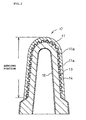
- This gas sensor element 10 includes a solid electrolyte layer 11 having a plurality of projections on its outer surface; an inner electrode 12 provided on the inner surface of the solid electrolyte layer 11; an outer electrode 13 provided on the outer surface of the solid electrolyte layer 11; and a spinel protection layer covering the outer electrode 13 for protection of the outer electrode 13.
- An electrical characteristic value as measured between the electrodes 12 and 13 varies according to a component of gas to be detected.
- Test Examples 1 and 4 respectively used pastes having the same composition.
- the base body and the drum were rotated in the same direction (i.e., the paste and the base body were moved in opposite directions), whereas in Test Examples 4 to 6, the base and the drum were rotated in opposite directions (i.e., the paste and the base body were moved in the same direction).
- the thus-obtained gas sensor elements of Test Examples 1 to 6 were examined in the following manner.
- the spinel protection layer was removed, and then the outer electrode was eluted into aqua regia.
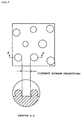
- the outer surface of the solid electrolyte layer was photographed through SEM and with respect to a square visual field of 500 ⁇ m by 500 ⁇ m.
- the thus-obtained photos were examined for an areal percentage of projections to the area of the visual field and the distance between neighboring projections. Table 1 shows the results of the examination. Sections of the gas sensor elements were also photographed through SEM.
- Test Example 1 Comparing Test Example 1 and Test Example 4, in Test Example 1 the base body and the drum rotated in the same direction, whereas in Test Example 4 the base body and the drum rotated in opposite directions.
- Test Examples 1 and 4 were identical in other conditions. In Test Example 1 "pores" were hardly formed or are not formed at all, whereas in Test Example 4 "pores” were considerably formed. This resulted from the following.
- Test Example 1 As shown in FIG. 3(a), while the paste was being applied onto the unfired base body by the overflow coating applicator 1, the paste did not stagnate at the position of contact between the base body and the paste present on the drum 2. Accordingly, when the base body was raised, the paste uniformly adhered to the outer surface of the base body.
- Test Example 4 as shown in FIG.
- Test Examples 1 to 6 were left within an autoclave which contained saturated water vapor at a temperature of 200°C(autoclave test for durability).
- the gas sensor element of Test Example 4 became defective after the elapse of 6 hours.
- Test Examples 1 and 5 it was not until 12 hours later that the gas sensor elements became defective.
- Test Examples 2, 3, and 6 the gas sensor elements were still sound even after the elapse of 12 hours.
- Test Example 4 conceivably, water vapor penetrated into "pores" formed between projections of the solid electrolyte layer; consequently, the phase transition of zirconia extended to considerably deep portions of projections.
- Test Examples other than Test Example 4 conceivably, "pores" were hardly formed or were not formed at all between projections; thus, sound durability was maintained under autoclave test conditions.
- Test Examples 1 and 5 conceivably, "pores" were slightly formed between projections, or the distance between neighboring projections was shorter than that in the case of Test Examples 2, 3, and 6; consequently, the gas sensor elements became defective slightly earlier than in the case of Test Examples 2, 3, and 6.
- the term “defective” refers to a case in which, after exposure to saturated water vapor having a temperature of 200°C for a predetermined period of time, an appearance defect; for example, detachment or cracking of the spinel layer is observed, or in which the breakaway of a projection(s) from the base body is found in observation of a section of the gas sensor element through SEM.
- the term “sound” refers to a case in which such anomalies are not observed.
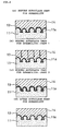
- FIGS. 4 and 5 associated with Test Example 2 (model of best durability) and Test Example 4 (model of poor durability), respectively.
- the arrow " ⁇ " indicates penetration of water vapor
- the shade "///” indicates a phase-transited layer of zirconia.
- Test Example 2 durability was conceivably held intact in the following manner.
- water vapor penetrated into the spinel protection layer 14 and reached the solid electrolyte layer 11 (see FIG. 4(b)).
- water vapor could attack only the surface of the solid electrolyte layer 11 (see FIG.
- Test Examples 1 to 6 were tested for thermal durability. A process of leaving the gas sensor elements exposed to heat having a temperature of 1000°C for 5 minutes and then allowing them to stand at the room temperature was defined as 1 cycle. The gas sensor elements were examined for the number of cycles (thermal durability) until the spinel protection layer came off. The results were as follows: 280 cycles for Test Examples 3 and 6; 430 cycles for Test Example 4; 850 cycles for Test Examples 1 and 5; and not less than 1000 cycles for Test Example 2. In Test Examples 3 and 6, the outer electrode was formed in such a manner as to penetrate into pits formed between projections.
- Test Examples 1, 2, and 5 a number of projections having favorable heat resistance were formed on the surface of the solid electrolyte layer while an appropriate distance was maintained between projections.
- the outer electrode was formed in such a manner as to penetrate into pits formed between projections.
- a strong bond was established between the solid electrolyte layer and the outer electrode and between the outer electrode and the spinel protection layer. This is a conceivable reason why the spinel protection layer did not easily come off.
- the gas sensor elements of Test Examples 1, 2, and 5 exhibit improved durability against high temperature and high humidity, while maintaining a strong bond between the solid electrolyte layer and the outer electrode and a strong bond between the outer electrode and the protection layer.
- the gas sensor elements of Test Examples 1, 2, and 5 are embodiments of the present invention. Particularly, the gas sensor element of Test Example 2 exhibits the best performance.
- the method for manufacturing the gas sensor elements of Test Examples 1 and 2 is the method for manufacturing a gas sensor element according to the present invention.
- the optimum rotational speed of the drum was judged to be 5 rpm to 15 rpm (equivalent to a moving speed of the paste of 2.4 cm/sec to 7.2 cm/sec at the position of contact between the paste and the base body); and the optimum rotational speed of the base body was judged to be 100 rpm to 700 rpm (equivalent to a moving speed of the base body of 3.4 cm/sec to 23.8 cm/sec at the position of contact between the paste and the base body).
Landscapes
- Chemical & Material Sciences (AREA)
- Life Sciences & Earth Sciences (AREA)
- Health & Medical Sciences (AREA)
- Physics & Mathematics (AREA)
- Chemical Kinetics & Catalysis (AREA)
- Electrochemistry (AREA)
- Molecular Biology (AREA)
- Analytical Chemistry (AREA)
- Biochemistry (AREA)
- General Health & Medical Sciences (AREA)
- General Physics & Mathematics (AREA)
- Immunology (AREA)
- Pathology (AREA)
- Measuring Oxygen Concentration In Cells (AREA)
Description
- The present invention relates to a gas sensor element which includes a solid electrolyte layer having a plurality of projections on its outer surface, an inner electrode provided on the inner surface of the solid electrolyte layer, an outer electrode provided on the outer surface of the solid electrolyte layer, and a protection layer covering the outer electrode for protection of the outer electrode and in which an electrical characteristic value as measured between the electrodes varies according to a component of gas to be detected.
- Conventionally, there is known a structure of and a manufacturing method for an oxygen concentration cell which exhibits such excellent heat resistance that an electrode does not come off even when the cell is exposed to a high-temperature environment for a long period of time. The manufacturing method comprises the steps of: applying a mixture of granules and minute particles onto the surface of a zirconia base body; and firing the base body and the applied mixture simultaneously to thereby form a number of pits and projections on the surface of the base body.
- For example, Japanese Patent Application Laid-Open (kokai) No. 56-160653 discloses a method for manufacturing a zirconia oxygen sensor element, including a step of applying a paste of mixed granules and minute particles onto a surface of a zirconia base body at a thickness of 40 µm to 300 µm through use of a brush. According to the publication, projections are formed on the surface of the base body through firing, and the surface is coated with an electrode. As a result, the electrode penetrates into pits formed between projections, thereby increasing its surface area and establishing a strong bond. Also, Japanese Patent Publication No. 2-44391 discloses a method for manufacturing a zirconia oxygen sensor element, including a step of applying a similar paste onto a surface of a zirconia base body in an overflowing manner through use of a roller so as to form a surface layer having a final thickness of 100 µm.
- In recent years, an oxygen concentration cell has often been required to be installed downstream of a three-way catalytic converter. Thus, the oxygen concentration cell must function properly in an environment having a temperature of 200°C to 300°C and that is rich with water vapor, in which zirconia is apt to undergo phase transition.
- However, the oxygen sensor elements described in Japanese Patent Application Laid-Open (kokai) No. 56-160653 and Japanese Patent Publication No. 2-44391 include portions where granules are present in layers, implying the formation of "pores" (a pore is a minute opening formed between neighboring projections as a result of bonding of tips of the projections or between layered projections). Thus, water vapor enters the "pores," causing the phase transition of zirconia to extend to considerably deep portions of projections. Accordingly, the projections change in volume on a microscopic scale, causing the formation of minute cracks in the projections. Therefore, the projections may break away from the zirconia base body to cause a crack failure.
- US patent 5,443,711 relates to an oxygen-sensor element including a solid-electrolyte body. On the inner side of the body, there is provided a platinum electrode. On the outer side of the body spherical protruded particles are provided and on the surface of these particles a further platinum electrode is formed.
- A porous protective layer is formed on the surface of the detection-gas-side electrode, wherein at least a part of said porous protective layer is formed by a granular texture of a grain size of 0.1 to 0.5 µm formed mainly of a non-stoichiometric compound of a transition metal oxide (TiOx), and a catalyst for having gas components of the gas to be measured react is carried in at least a part of the porous protective layer. Oxidation reaction of gas components is improved to prevent deterioration of the responsive property.
- In view of the foregoing, an object of the present invention is to provide a method of manufacturing a gas sensor element exhibiting improved durability against high temperature and high humidity while maintaining strong bond between a solid electrolyte layer and an outer electrode and a strong bond between the outer electrode and a protection layer.
- According to the present invention, there is provided a method for manufacturing a gas sensor element comprising the steps of: rotating a substantially cylindrical base body made of an unfired solid electrolyte material; applying a paste―which includes roughening particles of material substantially similar to that for the base body and has a viscosity of 500 CPS to 1600 CPS―onto the base body in such a manner that the paste is brought into contact with the base body and is moved in a direction opposite to a moving direction of the base body at a position of contact between the paste and the base body; and firing the base body coated with the paste to thereby form a plurality of projections on the base body.
- In the method for manufacturing a gas sensor element, the solid electrolyte material may contain as a main component stabilized or partially stabilized zirconia, for example, and, as needed, Al2O3, SiO2, and Fe2O3. The base body may be prepared by the steps of: mixing ZrO2 with a bivalent or trivalent metallic oxide, such as Y2O3, CaO, or MgO, in a desired proportion and pulverizing the resultant mixture; preliminarily firing the mixture in an electric furnace; pulverizing the preliminarily fired mixture to thereby obtain a material powder of stabilized or partially stabilized zirconia; and forming the material powder into a substantially cylindrical shape; for example, into a cylinder with one closed end, by way of a pressing method, such as a rubber press method, or by way of a laminating method, such as a thick-film method. The paste is a fluidized mixture, which includes roughening particles of material substantially similar to that for the base body. Material for the roughening particles is not necessarily identical to that for the base body, but must be basically identical in properties to that for the base body; otherwise, in the subsequent firing process, the base body and the roughening particles may not be integrated stably and reliably. The base body coated with the paste is dried and is then fired at a temperature of 1400°C to 1600°C for 1 to 3 hours, for example. An oxidizing atmosphere is usually preferred for firing.
- The base body having a plurality of projections formed thereon through firing serves as the solid electrolyte layer having a plurality of projections on its outer surface. An electrode is formed on each of the inner and outer surfaces of the solid electrolyte layer. Usually, a heat resistant, catalytic metal is used as material for the electrodes. Examples of such a metal include platinum, ruthenium, rhodium, palladium, and their alloys. Examples of the method for forming the electrodes include vacuum deposition, chemical deposition, electroless plating, electroplating, and a method composed of the steps of applying a decomposable metal salt onto the solid electrolyte layer and heating the coated solid electrolyte layer so as to deposit the metal through decomposition. The outer electrode is formed along the rugged surface of the solid electrolyte layer, thereby increasing the surface area of the electrode and improving adhesion of the electrode.
- According to the method for manufacturing a gas sensor element, the paste is moved in a direction opposite to a moving direction of the base body at the position of contact between the paste and the base body, thereby substantially uniformly applying the paste onto the outer surface of the rotating base body and thus substantially uniformly distributing roughening particles throughout the outer surface of the base body. This method for manufacturing a gas sensor element is suited for applying roughening particles in such a manner as to meet the following conditions: a plurality of projections are formed on a portion of or on the entirety of the region of the outer surface of the solid electrolyte layer that is covered with the protection layer; the plurality of projections are formed in a single layer; an area occupied by the projections accounts for 10% to 85% that of the portion of the outer surface of the solid electrolyte layer on which the projections are formed; and the distance between neighboring projections is 5 µm to 400 µm. Thus, the method is suited for manufacture of the gas sensor element according to the first aspect of the invention.
- Preferably, the paste is fed onto the outer circumferential surface of a rotary drum rotating in the same direction as does the base body, such that the fed paste is present in a predetermined thickness on the drum. In this case, through employment of a simple apparatus configuration, the paste and the base body can be moved in opposite directions at the position of contact between the paste and the base body. Preferably, in view of manufacture of the gas sensor element according to the first aspect of the invention, the axial rotational speed of the base body and the rotational speed of the rotary drum are regulated such that the base body is moved at a speed of 3.0 cm/sec to 24.0 cm/sec at the contact position and such that the paste is moved at a speed of 2.0 cm/sec to 8.0 cm/sec at the contact position. If the base body is moved at a speed of less than 3.0 cm/sec, the amount of the paste adhering to the base body increases; consequently, "pores" are more apt to be formed. If the base body is moved at a speed in excess of 24.0 cm/sec, the friction between the base body and the roughening particles contained in the paste tends to initiate wear on the base body. If the paste is moved at a speed of less than 2.0 cm/sec, the paste present on the rotary drum tends to flow downward due to its own weight. If the paste is moved at a speed in excess of 8.0 cm/sec, the amount of the paste adhering to the base body increases; consequently, "pores" are more apt to be formed.
- Preferably, the weight of the paste adhering to the base body is 5.0 mg/cm2 to 18.0 mg/cm2. If the weight of the paste adhering to the base body is less than 5.0 mg/cm2, formation of a sufficient number of projections on the surface of the base body becomes difficult to achieve; consequently, thermal durability may not be improved sufficiently. If the weight of the paste adhering to the base body is in excess of 18.0 mg/cm2, "pores" are apt to be formed.
- Preferably, the paste contains granules having a grain size of 20 µm to 100 µm and minute particles having a grain size smaller than that of the granules. A mixture of the granules and the minute particles serves as roughening particles. If the grain size of granules is less than 20 µm, formation of a number of projections having good heat resistance on the surface of the base body becomes difficult, which is similar to the case of formation of an unfavorable porous layer. If the grain size of granules is in excess of 100 µm, the granules themselves tend to fail in achieving a strong bond with the base body. A method for forming such favorable granules is not particularly limited, but granulation through use of a spray drier stabilizes the shape of granules and produces fine granules. The thus-produced granules exhibit an increased bonding force with the base body. Therefore, employment of a spray drier for granulation is preferred. According to granulation through use of a spray drier, a material powder mixed with an appropriate organic binder undergoes an ordinary wet method. The minute particles to be used are usually such that most of the minute particles have a grain size of not greater than 10 µm, preferably such that at least 80% of the minute particles have a grain size of not greater than 2.5 µm. Since the minute particles are used as sintering aids for aiding formation of a bond between the base body and the granules, particles having a relatively large grain size cannot sufficiently yield the required aiding effect.
- Preferably, the paste contains the granules and the minute particles in a mixing ratio of 80:20 to 20:80. If the ratio of the granules to the fine particles is in excess of 80:20, the granules tend to fail in achieving a strong bond with the surface of the base body. If the ratio of the granules to the minute particles is less than 20:80, formation of a sufficient number of projections on the surface of the base body becomes difficult, and thus thermal durability may not be sufficiently improved.
- The paste has a viscosity of 500 CPS to 1600 CPS, preferably 500 CPS to 1000 CPS. If the viscosity is less than 500 CPS, granules contained in the paste precipitate quickly; consequently, uniform formation of projections throughout the surface of the base body tends to become difficult. If the viscosity is in excess of 1600 CPS, projections tend to be formed in layers on the base body. In order to reliably prevent projections from being formed in layers on the base body, the upper limit of the viscosity is preferably set to 1000 CPS.
- Notably, an optimum paste for use in the method for manufacturing a gas sensor element according to the second aspect of the invention meets the following conditions: a mixed solvent of water and an organic binder contains granules and minute particles in a mixing ratio of 80:20 to 20:80―the granules have a grain size of 20 µm to 100 µm, and the fine particles are usually such that most of the minute particles have a grain size of not greater than 10 µm, preferably such that at least 80% of the minute particles have a grain size of not greater than 2.5 µm; viscosity is 500 CPS to 1000 CPS; and the paste applied onto the base body has a thickness of 20 µm to 200 µm. The mixed solvent preferably contains water and an organic binder in a mixing ratio of 200:1 to 20:1. Examples of such an organic binder include Na-CMC (sodium cellulose glycolate), NH4-CMC (ammonium cellulose glycolate), and PVA (polyvinyl alcohol). The mixing ratio of water and an organic binder greatly influences the viscosity of the paste. For example, in the case of using NH4-CMC, if the ratio of water to NH4-CMC is in excess of 200:1, the viscosity of the paste decreases, and thus granules contained in the paste precipitate quickly; consequently, uniform formation of projections throughout the surface of the base body tends to become difficult. If the ratio of water to NH4-CMC is less than 20:1, the viscosity of the paste increases; consequently, projections tend to be formed in layers on the base body. Further, after firing, binder portions tend to result in formation of "pores."
- Preferred embodiments of the invention will now be described by way of example, with reference to the accompanying drawings, in which:
- FIG. 1 comprises views for explaining an overflow coating applicator, wherein FIG. 1(a) is a schematic perspective view, and FIG. 1(b) is a schematic sectional view.
- FIG. 2 is a schematic sectional view of a gas sensor element.
- FIG. 3 comprises views for explaining a generation mechanism of "pores" in overflow coating, wherein FIG. 3(a) is a view associated with Test Example 1, and FIG. 3(b) is a view associated with Test Example 4.
- FIG. 4 comprises views for explaining variation in projections during autoclave test for durability in the case of Test Example 2.
- FIG. 5 comprises views for explaining variation in projections during autoclave test for durability in the case of Test Example 4.
- FIG. 6 is a graph showing relationship among the rotational speed of a drum, the rotational speed of a base body, and the weight of adhering paste.
- FIG. 7 is a schematic view representing an SEM photo of the outer surface of a solid electrolyte layer.
-
- The following Table 1 provides details concerning the methods of preparation, and the evaluation results of Test Examples 1 to 6, as referred to hereinafter.
Test Examples 1 2 3 4 5 6 P
a
s
t
eFine particles
(g)910 455 455 910 455 455 Preliminarily fired granules (g) 490 245 245 490 245 245 Binder (g) 27 23 23 27 23 23 Water (g) 1800 1800 2800 1800 1800 2800 Viscosity (CPS) 1600 850 400 1600 850 400 Rotational directions of base and drum Same Same Same Opposite Opposite Opposite Areal percentage of projections in 500 x 500 µm visual field (%) 70-80 50-70 ≤ 10 0 ≥90 60-85 ≤10 Distance between projections (µm) 20-30 50-280 ≤400 0-10 5-270 ≥400 Autoclave test for durability (200°C) 3 hr. o o o o o o 6 hr. o o o x o o 9 hr. o o o x o o 12 hr. x o o x x o Thermal durability (cycles) 850 ≥1000 280 430 850 280 Overall evaluation BBB AAA XXX XXX BBB XXX AAA: excellent; BBB: good; XXX: poor - First, a base body was prepared by the following process.
- 6 Mol% yttrium oxide was added to zirconium oxide. The resultant mixture was wet pulverized for 70 hours. The pulverized mixture was dried and was then put through a 20-mesh sieve. The obtained particles were preliminarily fired at 1300°C for 1 hour in an electric furnace. The fired particles were put through a 20-mesh sieve. Then, the obtained particles were wet pulverized for 50 hours through use of a ball mill, obtaining material powder in which particles having a grain size of not greater than 2.5 µm account for 90% of the entire material powder. Gum arabic serving as an organic binder was added to the material powder, obtaining slurry. The obtained slurry was processed through use of a spray drier, yielding granules having an average grain size of about 60 µm. The water content of the granules was adjusted to 1%. The granules were then formed into a base body having a cylindrical shape with one closed end (i.e., a cup shape, or a closed-bottomed cylindrical shape) through use of a 50 Pa rubber press. This base body includes a sensing portion (a portion covered with a spinel protection layer, which will be described later) having an average diameter of 6.5 mm and an outer surface area of about 5.7 cm2.
- The above granules obtained by processing through use of the spray drier were preliminarily fired at a temperature of 1200°C to 1300°C for 1 hour, followed by sieving to obtain granules having a grain size of 60 µm to 100 µm. The thus-obtained granules and the fine particles at least 80% of which have a grain size of not greater than 2.5 µm were added in ratios as shown in Table 1 to a mixed solvent of water and water-soluble binder NH4-CMC, yielding a paste having a viscosity of 400 CPS to 1600 CPS.
- This paste was applied onto a portion (sensing portion) of the outer surface of the above
unfired base body 7, which portion is to be covered with a spinel protection layer (described later), through overflow coating by means of a roller. The base body coated with the paste was fired at 1600°C for 1 hour in an oxidizing atmosphere. As shown in FIG. 1, anoverflow coating applicator 1 includes a rotary drum 2 (diameter: 90 mm), apaste feeder 3, aplate 4, and a rotary base-body support 5. Therotary drum 2 is adapted to apply the paste onto the unfired base body. Thepaste feeder 3 feeds thepaste 8 onto the outer circumferential surface of therotary drum 2. Theplate 4 is adapted to scrape off the paste such that the thickness of the paste applied onto the outer circumferential surface of therotary drum 2 becomes constant (herein, 300 µm). The rotary base-body support 5 is adapted to support the unfired base body such that the unfired base body can rotate about its axis and comes into contact with the paste applied onto the outer circumferential surface of therotary drum 2. The rotary base-body support 5 can switch directions of its rotation. As shown in Table 1, the direction of rotation of the rotary base-body support 5 was set identical to or opposite to that of therotary drum 2 for individual Test Examples. Theoverflow coating applicator 1 was adjusted such that the rotational speed of the drum became 10 rpm (the speed of the paste became 4.8 cm/sec at a position of contact between the paste and the base body), and the rotational speed of the rotary base-body support 5 became 300 rpm (the speed of the base body became 10.2 cm/sec at the position of contact between the paste and the base body). A tip portion (bottom portion) of the base body is coated with the paste through the rising effect of the paste. - After the base body was fired (the fired base body is referred to as a solid electrolyte layer), a platinum electrode was formed on the inner and outer surfaces of the solid electrolyte layer by way of a known plating method. Further, a spinel protection layer was formed on the outer electrode by way of a known plasmatic thermal spraying method, thereby obtaining a gas sensor element as shown in FIG. 2. This
gas sensor element 10 includes asolid electrolyte layer 11 having a plurality of projections on its outer surface; aninner electrode 12 provided on the inner surface of thesolid electrolyte layer 11; anouter electrode 13 provided on the outer surface of thesolid electrolyte layer 11; and a spinel protection layer covering theouter electrode 13 for protection of theouter electrode 13. An electrical characteristic value as measured between theelectrodes - Test Examples 1 and 4, Test Examples 2 and 5, and Test Examples 3 and 6 respectively used pastes having the same composition. In Test Examples 1 to 3, the base body and the drum were rotated in the same direction (i.e., the paste and the base body were moved in opposite directions), whereas in Test Examples 4 to 6, the base and the drum were rotated in opposite directions (i.e., the paste and the base body were moved in the same direction).
- The thus-obtained gas sensor elements of Test Examples 1 to 6 were examined in the following manner. The spinel protection layer was removed, and then the outer electrode was eluted into aqua regia. Subsequently, the outer surface of the solid electrolyte layer was photographed through SEM and with respect to a square visual field of 500 µm by 500 µm. The thus-obtained photos were examined for an areal percentage of projections to the area of the visual field and the distance between neighboring projections. Table 1 shows the results of the examination. Sections of the gas sensor elements were also photographed through SEM. The thus-obtained photos were examined for "pores." In the gas sensor elements other than that of Test Example 4, projections were formed in a single layer, and "pores" were hardly formed or were not formed at all. By contrast, in the gas sensor element of Test Example 4, projections were formed in layers, and "pores" were considerably formed.
- Comparing Test Example 1 and Test Example 4, in Test Example 1 the base body and the drum rotated in the same direction, whereas in Test Example 4 the base body and the drum rotated in opposite directions. Test Examples 1 and 4 were identical in other conditions. In Test Example 1 "pores" were hardly formed or are not formed at all, whereas in Test Example 4 "pores" were considerably formed. This resulted from the following. In Test Example 1, as shown in FIG. 3(a), while the paste was being applied onto the unfired base body by the
overflow coating applicator 1, the paste did not stagnate at the position of contact between the base body and the paste present on thedrum 2. Accordingly, when the base body was raised, the paste uniformly adhered to the outer surface of the base body. By contrast, in Test Example 4, as shown in FIG. 3(b), during overflow coating, the paste stagnated at the position 6 of contact between the base body and the paste present on thedrum 2. As a result, when the base body was raised, the paste did not uniformly adhere to the outer surface of the base body, causing formation of a coated portion where projections were arranged in layers. In such a coated portion, many "pores" were formed. - Also, the gas sensor elements of Test Examples 1 to 6 were left within an autoclave which contained saturated water vapor at a temperature of 200°C(autoclave test for durability). The gas sensor element of Test Example 4 became defective after the elapse of 6 hours. By contrast, in Test Examples 1 and 5, it was not until 12 hours later that the gas sensor elements became defective. In Test Examples 2, 3, and 6, the gas sensor elements were still sound even after the elapse of 12 hours. In Test Example 4, conceivably, water vapor penetrated into "pores" formed between projections of the solid electrolyte layer; consequently, the phase transition of zirconia extended to considerably deep portions of projections. As a result, at a relatively early stage, the projections changed in volume on a microscopic scale, causing the formation of minute cracks in the projections. Hence, the gas sensor element of Test Example 4 became defective. In Test Examples other than Test Example 4, conceivably, "pores" were hardly formed or were not formed at all between projections; thus, sound durability was maintained under autoclave test conditions. In Test Examples 1 and 5, conceivably, "pores" were slightly formed between projections, or the distance between neighboring projections was shorter than that in the case of Test Examples 2, 3, and 6; consequently, the gas sensor elements became defective slightly earlier than in the case of Test Examples 2, 3, and 6. Notably, the term "defective" refers to a case in which, after exposure to saturated water vapor having a temperature of 200°C for a predetermined period of time, an appearance defect; for example, detachment or cracking of the spinel layer is observed, or in which the breakaway of a projection(s) from the base body is found in observation of a section of the gas sensor element through SEM. The term "sound" refers to a case in which such anomalies are not observed.
- The mechanism of durability under autoclave test conditions will next be described with reference to FIGS. 4 and 5 associated with Test Example 2 (model of best durability) and Test Example 4 (model of poor durability), respectively. In FIGS. 4 and 5, the arrow "←" indicates penetration of water vapor, and the shade "///" indicates a phase-transited layer of zirconia. In the case of Test Example 2, durability was conceivably held intact in the following manner. During the autoclave test for durability as shown in FIG. 4, water vapor penetrated into the
spinel protection layer 14 and reached the solid electrolyte layer 11 (see FIG. 4(b)). However, since water vapor could attack only the surface of the solid electrolyte layer 11 (see FIG. 4(c)),projections 11a did not break away and were maintained in a sound state (see FIG. 4(d)). By contrast, in the case of Test Example 4, durability was conceivably impaired in the following manner. During the autoclave test for durability as shown in FIG. 5, water vapor reached considerably deep portions of theprojections 11a (see FIG. 5(b)), since "pores" were formed between theprojections 11a present in layers. Thus, water vapor attacked theprojections 11a from every direction. The thus-attacked zirconia suffered the progress of phase transition (see FIG. 5(c)). As a result, theprojections 11a broke away (see FIG. 5(d)). The breakaway of theprojection 11a starts at its relatively weak portion, resulting from a failure to endure a change in volume caused by the phase transition. When the breakaway of theprojections 11a is significant, thespinel protection layer 14 may crack. - Also, the gas sensor elements of Test Examples 1 to 6 were tested for thermal durability. A process of leaving the gas sensor elements exposed to heat having a temperature of 1000°C for 5 minutes and then allowing them to stand at the room temperature was defined as 1 cycle. The gas sensor elements were examined for the number of cycles (thermal durability) until the spinel protection layer came off. The results were as follows: 280 cycles for Test Examples 3 and 6; 430 cycles for Test Example 4; 850 cycles for Test Examples 1 and 5; and not less than 1000 cycles for Test Example 2. In Test Examples 3 and 6, the outer electrode was formed in such a manner as to penetrate into pits formed between projections. However, since the distance between projections is relatively large, a strong bond was not established between the solid electrolyte layer and the outer electrode and between the outer electrode and the spinel protection layer. This is a conceivable reason why the spinel protection layer came off in a relatively small number of cycles. In Test Example 4, projections having favorable heat resistance were not formed in sufficient quantity on the surface of the solid electrolyte layer. This is equivalent to a state in which a porous layer is formed. As a result, a strong bond was not established between the solid electrolyte layer and the outer electrode and between the outer electrode and the spinel protection layer. This is a conceivable reason whey the spinel protection layer came off in a relatively small number of cycles. By contrast, in Test Examples 1, 2, and 5, a number of projections having favorable heat resistance were formed on the surface of the solid electrolyte layer while an appropriate distance was maintained between projections. Thus, the outer electrode was formed in such a manner as to penetrate into pits formed between projections. Also, a strong bond was established between the solid electrolyte layer and the outer electrode and between the outer electrode and the spinel protection layer. This is a conceivable reason why the spinel protection layer did not easily come off.
- As described above, the gas sensor elements of Test Examples 1, 2, and 5 exhibit improved durability against high temperature and high humidity, while maintaining a strong bond between the solid electrolyte layer and the outer electrode and a strong bond between the outer electrode and the protection layer. The gas sensor elements of Test Examples 1, 2, and 5 are embodiments of the present invention. Particularly, the gas sensor element of Test Example 2 exhibits the best performance. The method for manufacturing the gas sensor elements of Test Examples 1 and 2 is the method for manufacturing a gas sensor element according to the present invention.
- Through use of the above overflow coating applicator (drum diameter: 90 mm; base body diameter: 6.5 mm) and the paste of Test Example 2, how the weight of paste adhering to the base body varies with the rotational speed of the drum and with the rotational speed of the base body was examined. The results are shown in Fig. 6. At a weight of adhering paste of 30 mg to 100 mg (represented by the shaded area of FIG. 6; equivalent weight per unit area: about 5.0-18.0 mg/cm2), "pores" were hardly formed or were not formed at all; durability under autoclave test conditions was improved; and a number of projections were formed at appropriate intervals on the surface of the base body, thereby exhibiting improved thermal durability against coming off of the spinel protection layer and of the outer electrode.
- At a rotational speed of the drum of less than 5 rpm, the paste present on the rotary drum ran downward due to its own weight. At a rotational speed of the drum in excess of 15 rpm, the weight of paste adhering to the base body tended to vary greatly with the rotational speed of the base body; thus, uniform application of the paste onto the outer surface of the base body tended to become difficult to achieve.
- At a rotational speed of the base body in excess of 700 rpm, significant friction between the base body and granules contained in the paste caused scratches on the base body and thus caused the base body to wear. At a rotational speed of the base body of less than 100 rpm, the weight of paste adhering to the base body tended to vary greatly with the rotational speed of the drum; thus, uniform application of the paste onto the outer surface of the base body tended to become difficult to achieve.
- From the above test results, for the overflow coating application of FIG. 6, the optimum rotational speed of the drum was judged to be 5 rpm to 15 rpm (equivalent to a moving speed of the paste of 2.4 cm/sec to 7.2 cm/sec at the position of contact between the paste and the base body); and the optimum rotational speed of the base body was judged to be 100 rpm to 700 rpm (equivalent to a moving speed of the base body of 3.4 cm/sec to 23.8 cm/sec at the position of contact between the paste and the base body).
Claims (7)
- A method for manufacturing a gas sensor element,
characterised by the steps of: rotating a substantially cylindrical base body (7) made of an unfired solid electrolyte material; applying a paste―which includes roughening particles of material substantially similar to that for the base body and has a viscosity of 500 CPS to 1600 CPS―onto the base body in such a manner that the paste is
brought into contact with the base body and is moved in a direction opposite to a moving direction of the base body at a position of contact between the paste and the base body; and firing the base body coated with the paste to thereby form a plurality of projections on the base body. - A method for manufacturing a gas sensor element according to Claim 1, wherein the paste is fed onto the outer circumferential surface of a rotary drum (2) rotating in the same direction as does the base body, such that the fed paste is present in a predetermined thickness on the drum.
- A method for manufacturing a gas sensor element according to Claim 2, wherein the base body is moved at a speed of 3.0 cm/sec to 24.0 cm/sec at the contact position and such that the paste is moved at a speed of 2.0 cm/sec to 8.0 cm/sec at the contact position.
- A method for manufacturing a gas sensor element according to any of Claims 1 to 3, wherein the weight of the paste adhering to the base body is 5.0 mg/cm2 to 18.0 mg/cm2.
- A method for manufacturing a gas sensor element according to any of Claims 1 to 3, wherein the paste contains granules having a grain size of 20 µm to 100 µm and minute particles having a grain size smaller than that of the granules, and a mixture of the granules and the minute particles serves as the roughening particles.
- A method for manufacturing a gas sensor element according to Claim 5, wherein the paste contains the granules and the minute particles in a mixing ratio of 80:20 to 20:80.
- A method for manufacturing a gas sensor element according to any of Claims 1 to 6, wherein the paste has a viscosity of 500 CPS to 1000 CPS.
Applications Claiming Priority (2)
| Application Number | Priority Date | Filing Date | Title |
|---|---|---|---|
| JP03319598A JP3634956B2 (en) | 1998-02-16 | 1998-02-16 | Manufacturing method of gas sensor element |
| JP3319598 | 1998-02-16 |
Publications (3)
| Publication Number | Publication Date |
|---|---|
| EP0936463A2 EP0936463A2 (en) | 1999-08-18 |
| EP0936463A3 EP0936463A3 (en) | 2000-12-27 |
| EP0936463B1 true EP0936463B1 (en) | 2005-04-13 |
Family
ID=12379712
Family Applications (1)
| Application Number | Title | Priority Date | Filing Date |
|---|---|---|---|
| EP99300991A Expired - Lifetime EP0936463B1 (en) | 1998-02-16 | 1999-02-10 | Gas sensor element and method for manufacturing the element |
Country Status (4)
| Country | Link |
|---|---|
| US (1) | US6544586B1 (en) |
| EP (1) | EP0936463B1 (en) |
| JP (1) | JP3634956B2 (en) |
| DE (1) | DE69924654T2 (en) |
Families Citing this family (8)
| Publication number | Priority date | Publication date | Assignee | Title |
|---|---|---|---|---|
| JP2002323473A (en) * | 2001-04-24 | 2002-11-08 | Denso Corp | Gas sensor element manufacturing method and thermal spraying apparatus |
| JP4622146B2 (en) * | 2001-04-25 | 2011-02-02 | 株式会社デンソー | Method for manufacturing gas sensor element |
| US8097137B2 (en) | 2008-09-05 | 2012-01-17 | Ngk Spark Plug Co., Ltd. | Gas sensor element and gas sensor |
| JP5639032B2 (en) * | 2011-11-08 | 2014-12-10 | 日本特殊陶業株式会社 | Gas sensor element and gas sensor |
| JP5722829B2 (en) | 2012-06-12 | 2015-05-27 | 日本特殊陶業株式会社 | Gas sensor |
| DE102015222108A1 (en) * | 2015-11-10 | 2017-05-11 | Robert Bosch Gmbh | Sensor element and method for producing a sensor element |
| JP2018009817A (en) | 2016-07-11 | 2018-01-18 | 株式会社デンソー | Gas sensor |
| JP7270565B2 (en) * | 2020-02-17 | 2023-05-10 | 日本特殊陶業株式会社 | Sensor element and gas sensor |
Citations (1)
| Publication number | Priority date | Publication date | Assignee | Title |
|---|---|---|---|---|
| EP0709671A1 (en) * | 1994-10-28 | 1996-05-01 | Nippondenso Co., Ltd. | Oxygen sensor element |
Family Cites Families (22)
| Publication number | Priority date | Publication date | Assignee | Title |
|---|---|---|---|---|
| JPS5254493A (en) | 1975-10-29 | 1977-05-02 | Nissan Motor | Oxygen sensor |
| JPS5268494A (en) | 1975-12-03 | 1977-06-07 | Nippon Denso Co Ltd | Oxygen concentration detector |
| JPS5310491A (en) | 1976-07-16 | 1978-01-30 | Nippon Denso Co Ltd | Oxygen concentration detector |
| JPS5385493A (en) | 1977-01-05 | 1978-07-27 | Hitachi Ltd | Oxygen concentration sensor |
| JPS5466888A (en) | 1977-11-07 | 1979-05-29 | Matsushita Electric Ind Co Ltd | Production of electrode for oxygen sensor |
| US4136000A (en) | 1978-03-13 | 1979-01-23 | Bendix Autolite Corporation | Process for producing improved solid electrolyte oxygen gas sensors |
| JPS56160653A (en) | 1980-05-14 | 1981-12-10 | Ngk Spark Plug Co Ltd | Manufacture of oxygen concentration cell |
| JPS58204365A (en) | 1982-05-24 | 1983-11-29 | Japan Electronic Control Syst Co Ltd | O↓2 sensor |
| JPS62198749A (en) | 1986-02-26 | 1987-09-02 | Nippon Denso Co Ltd | Oxygen concentration detector |
| JPS6398558A (en) | 1986-10-15 | 1988-04-30 | Mitsubishi Heavy Ind Ltd | Preparation of element for detecting concentration of oxygen |
| JPH0650297B2 (en) * | 1986-12-27 | 1994-06-29 | 日本碍子株式会社 | Method of manufacturing oxygen sensor element |
| JPH0731150B2 (en) | 1987-02-16 | 1995-04-10 | 日本碍子株式会社 | Oxygen sensor element and manufacturing method thereof |
| JPH0778481B2 (en) | 1987-02-16 | 1995-08-23 | 日本碍子株式会社 | Method of manufacturing oxygen sensor element |
| JPH0752171B2 (en) | 1987-05-30 | 1995-06-05 | 日本碍子株式会社 | Electrochemical device |
| JPH01132947A (en) | 1987-11-18 | 1989-05-25 | Toyota Motor Corp | Ceramic substrate with metal oxide semiconductor film and manufacture thereof |
| JPH01209355A (en) | 1988-02-17 | 1989-08-23 | Ngk Insulators Ltd | Manufacture of oxygen sensor element |
| JP2514701B2 (en) * | 1988-12-02 | 1996-07-10 | 日本特殊陶業株式会社 | Oxygen sensor |
| DE3923193A1 (en) * | 1989-07-13 | 1991-01-24 | Max Planck Gesellschaft | LIMIT CURRENT SENSOR FOR MEASURING THE PARTIAL PRESSURE OF A GAS |
| JPH05180797A (en) | 1991-12-27 | 1993-07-23 | Toyota Motor Corp | Oxygen concentration sensor |
| US5681784A (en) | 1992-07-03 | 1997-10-28 | Robert Bosch Gmbh | Thermal shock resistant ceramic |
| DE4221786C2 (en) * | 1992-07-03 | 1995-12-14 | Bosch Gmbh Robert | Temperature-resistant ceramic |
| US5514758A (en) | 1994-09-30 | 1996-05-07 | The Goodyear Tire & Rubber Company | Process for making latex for high performance masking tape |
-
1998
- 1998-02-16 JP JP03319598A patent/JP3634956B2/en not_active Expired - Fee Related
-
1999
- 1999-02-10 DE DE69924654T patent/DE69924654T2/en not_active Expired - Lifetime
- 1999-02-10 EP EP99300991A patent/EP0936463B1/en not_active Expired - Lifetime
- 1999-02-12 US US09/249,370 patent/US6544586B1/en not_active Expired - Fee Related
Patent Citations (1)
| Publication number | Priority date | Publication date | Assignee | Title |
|---|---|---|---|---|
| EP0709671A1 (en) * | 1994-10-28 | 1996-05-01 | Nippondenso Co., Ltd. | Oxygen sensor element |
Also Published As
| Publication number | Publication date |
|---|---|
| EP0936463A3 (en) | 2000-12-27 |
| EP0936463A2 (en) | 1999-08-18 |
| JPH11230930A (en) | 1999-08-27 |
| US6544586B1 (en) | 2003-04-08 |
| DE69924654D1 (en) | 2005-05-19 |
| JP3634956B2 (en) | 2005-03-30 |
| DE69924654T2 (en) | 2006-03-02 |
Similar Documents
| Publication | Publication Date | Title |
|---|---|---|
| EP0372425A2 (en) | Oxygen-sensor element and method for producing the same | |
| US5326597A (en) | Method of producing oxygen sensor for air-fuel ratio control having a protective layer including oxygen storage material | |
| EP0809101B1 (en) | Oxygen sensor element and method of producing same | |
| EP1195601B1 (en) | Oxygen sensor element and manufacturing method thereof | |
| US4477487A (en) | Method of producing oxygen concentration cells | |
| US4720394A (en) | Gas sensor with ceramics substrate and method for producing the same | |
| JPH07270375A (en) | Exhaust gas sensor including composite tile detection element and method of manufacturing the same | |
| JP4758117B2 (en) | Gas sensor element and manufacturing method thereof | |
| US6544586B1 (en) | Method for manufacturing gas sensor element | |
| JP5187417B2 (en) | Gas sensor element and manufacturing method thereof | |
| US6672137B1 (en) | Oxygen sensor and manufacturing method of sensor element | |
| EP1215487A1 (en) | Low-density coating for gas sensors | |
| JP2574452B2 (en) | Oxygen sensor, method of manufacturing the same, and method of preventing poisoning | |
| KR19990008442A (en) | Lateral high resistance for zinc oxide varistors, and methods for producing zinc oxide varistors and zinc dioxide varistors using the same | |
| US20210156817A1 (en) | Ceramic structured body and sensor element of gas sensor | |
| JP3766572B2 (en) | Method for manufacturing oxygen sensor element | |
| JPS6126022B2 (en) | ||
| JPH087177B2 (en) | Oxygen sensor element and manufacturing method thereof | |
| JP2603373B2 (en) | Electrochemical element | |
| JPS57186161A (en) | Manufacture of substrate for gas sensor element with heater | |
| JP2589130B2 (en) | Oxygen sensor element | |
| JP3616510B2 (en) | Oxygen sensor and manufacturing method thereof | |
| JPH02310459A (en) | Production of oxygen sensor element for controlling air-fuel ratio | |
| JP4622146B2 (en) | Method for manufacturing gas sensor element | |
| JP2957542B1 (en) | Gas sensor element and manufacturing method thereof |
Legal Events
| Date | Code | Title | Description |
|---|---|---|---|
| PUAI | Public reference made under article 153(3) epc to a published international application that has entered the european phase |
Free format text: ORIGINAL CODE: 0009012 |
|
| AK | Designated contracting states |
Kind code of ref document: A2 Designated state(s): DE FR GB IT |
|
| AX | Request for extension of the european patent |
Free format text: AL;LT;LV;MK;RO;SI |
|
| PUAL | Search report despatched |
Free format text: ORIGINAL CODE: 0009013 |
|
| AK | Designated contracting states |
Kind code of ref document: A3 Designated state(s): AT BE CH CY DE DK ES FI FR GB GR IE IT LI LU MC NL PT SE |
|
| AX | Request for extension of the european patent |
Free format text: AL;LT;LV;MK;RO;SI |
|
| 17P | Request for examination filed |
Effective date: 20010125 |
|
| AKX | Designation fees paid |
Free format text: DE FR GB IT |
|
| 17Q | First examination report despatched |
Effective date: 20020215 |
|
| GRAP | Despatch of communication of intention to grant a patent |
Free format text: ORIGINAL CODE: EPIDOSNIGR1 |
|
| GRAS | Grant fee paid |
Free format text: ORIGINAL CODE: EPIDOSNIGR3 |
|
| GRAA | (expected) grant |
Free format text: ORIGINAL CODE: 0009210 |
|
| AK | Designated contracting states |
Kind code of ref document: B1 Designated state(s): DE FR GB IT |
|
| PG25 | Lapsed in a contracting state [announced via postgrant information from national office to epo] |
Ref country code: IT Free format text: LAPSE BECAUSE OF FAILURE TO SUBMIT A TRANSLATION OF THE DESCRIPTION OR TO PAY THE FEE WITHIN THE PRESCRIBED TIME-LIMIT;WARNING: LAPSES OF ITALIAN PATENTS WITH EFFECTIVE DATE BEFORE 2007 MAY HAVE OCCURRED AT ANY TIME BEFORE 2007. THE CORRECT EFFECTIVE DATE MAY BE DIFFERENT FROM THE ONE RECORDED. Effective date: 20050413 |
|
| REG | Reference to a national code |
Ref country code: GB Ref legal event code: FG4D |
|
| REF | Corresponds to: |
Ref document number: 69924654 Country of ref document: DE Date of ref document: 20050519 Kind code of ref document: P |
|
| PG25 | Lapsed in a contracting state [announced via postgrant information from national office to epo] |
Ref country code: GB Free format text: LAPSE BECAUSE OF NON-PAYMENT OF DUE FEES Effective date: 20060210 |
|
| PLBE | No opposition filed within time limit |
Free format text: ORIGINAL CODE: 0009261 |
|
| STAA | Information on the status of an ep patent application or granted ep patent |
Free format text: STATUS: NO OPPOSITION FILED WITHIN TIME LIMIT |
|
| ET | Fr: translation filed | ||
| 26N | No opposition filed |
Effective date: 20060116 |
|
| GBPC | Gb: european patent ceased through non-payment of renewal fee |
Effective date: 20060210 |
|
| PGFP | Annual fee paid to national office [announced via postgrant information from national office to epo] |
Ref country code: FR Payment date: 20140211 Year of fee payment: 16 |
|
| PGFP | Annual fee paid to national office [announced via postgrant information from national office to epo] |
Ref country code: DE Payment date: 20140417 Year of fee payment: 16 |
|
| REG | Reference to a national code |
Ref country code: DE Ref legal event code: R119 Ref document number: 69924654 Country of ref document: DE |
|
| REG | Reference to a national code |
Ref country code: FR Ref legal event code: ST Effective date: 20151030 |
|
| PG25 | Lapsed in a contracting state [announced via postgrant information from national office to epo] |
Ref country code: DE Free format text: LAPSE BECAUSE OF NON-PAYMENT OF DUE FEES Effective date: 20150901 |
|
| PG25 | Lapsed in a contracting state [announced via postgrant information from national office to epo] |
Ref country code: FR Free format text: LAPSE BECAUSE OF NON-PAYMENT OF DUE FEES Effective date: 20150302 |