EP0809101B1 - Oxygen sensor element and method of producing same - Google Patents
Oxygen sensor element and method of producing same Download PDFInfo
- Publication number
- EP0809101B1 EP0809101B1 EP97108239A EP97108239A EP0809101B1 EP 0809101 B1 EP0809101 B1 EP 0809101B1 EP 97108239 A EP97108239 A EP 97108239A EP 97108239 A EP97108239 A EP 97108239A EP 0809101 B1 EP0809101 B1 EP 0809101B1
- Authority
- EP
- European Patent Office
- Prior art keywords
- electrode
- solid electrolyte
- noble metal
- cavities
- oxygen sensor
- Prior art date
- Legal status (The legal status is an assumption and is not a legal conclusion. Google has not performed a legal analysis and makes no representation as to the accuracy of the status listed.)
- Expired - Lifetime
Links
Images


Classifications
-
- G—PHYSICS
- G01—MEASURING; TESTING
- G01N—INVESTIGATING OR ANALYSING MATERIALS BY DETERMINING THEIR CHEMICAL OR PHYSICAL PROPERTIES
- G01N27/00—Investigating or analysing materials by the use of electric, electrochemical, or magnetic means
- G01N27/26—Investigating or analysing materials by the use of electric, electrochemical, or magnetic means by investigating electrochemical variables; by using electrolysis or electrophoresis
- G01N27/403—Cells and electrode assemblies
- G01N27/406—Cells and probes with solid electrolytes
- G01N27/407—Cells and probes with solid electrolytes for investigating or analysing gases
- G01N27/4075—Composition or fabrication of the electrodes and coatings thereon, e.g. catalysts
Definitions
- the present invention relates to an oxygen sensor element which can be used in an air-fuel ratio control for an automobile engine, and further relates to a method of producing such an oxygen sensor element.
- an oxygen sensor is provided for measuring the oxygen concentration in the exhaust gas so as to perform an air-fuel ratio control based on measured values of the oxygen concentration.
- the oxygen sensor includes an oxygen sensor element for detecting the oxygen concentration.
- the oxygen sensor element includes a solid electrolyte and electrodes provided on the solid electrolyte.
- the electrodes include an internal electrode exposed to a reference gas and an external electrode exposed to a gas to be measured.
- noble metal nuclei are adhered to the electrode forming portions of the solid electrolyte to form nucleus forming portions. Then. metal plating is applied to the nucleus forming portions to form plating films. Thereafter, the plating films are burned to form the foregoing electrodes on the solid electrolyte.
- nucleus forming portions are achieved by spraying particles of noble metal, such as platinum (Pt), onto the electrode forming portions of the solid electrolyte.
- noble metal such as platinum (Pt)
- a large number of fine holes or cavities are formed on the surface of the solid electrolyte. Accordingly, when the noble metal particles are applied onto the surface of the solid electrolyte at the electrode forming portions thereof, the noble metal particles enter the cavities of the solid electrolyte to form the nucleus forming portions. Thus, upon plating the nucleus forming portions, a plating liquid reacts with the noble metal particles within the cavities so that the plating films are organically tangled with particles of the solid electrolyte to achieve a strong adhesion force therebetween based on an anchor effect. Then, by burning the plating films, the electrodes are achieved which are hard to peel off from the surface of the solid electrolyte.
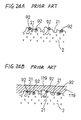
- a complicated pattern as the foregoing electrode, on the surface of the solid electrolyte as shown, for example, in Fig. 2A and Fig. 9. Accordingly, in the foregoing forming method employing spraying of the noble metal particles, it is necessary to partially mask the surface of the solid electrolyte and thus it is difficult to produce the electrode of a complicated shape.
- U.S. Patent US-A-4 477487 is provided for preventing the electrode from being peeled from the solid electrolyte.
- electrode-adhering particels consist essentially of a limited amount of stabilized or partially stabilized zirconia granulated particels having a spherical shape and a particle size of not smaller than 44 ⁇ m and a limited amount of zirconia fine particles having a particle size of not larger than 10 ⁇ m. These electrode-adhering particles are applied and adhered to the surface of a matrix consisting of stabilized or partially stabilized zirconia.
- U.S. Patent Publication No. 4 851 105 discloses an oxygen sensing element adapted primarily to determine an oxygen partial pressure of a measured gas, including a solid electrolyte body having a surface, at least a portion of which is undulated.
- the electrode is covered by a porous protective coating so that, on the basis of the function of the undulated portion, it is possible to improve the anti-peel-off durability of the coating.
- Patent Publication No. EP-A-0 709 671 disclose an oxygen sensor element which includes a solid electrolyte having a side surface at one side thereof, the side surface being contactable with a gas to be measured, and a skeletal electrode provided on the side surface.
- Japanese First (unexamined) Patent Publication No. 4-95766 discloses another forming method, wherein a solution containing a noble metal compound is applied to the electrode forming portions of the solid electrolyte to form coating films and then, by heating the coating films at a high temperature, those components (for example, a binder) other than the noble metal in the solution are volatilized or decomposed so that only the noble metal nuclei are deposited to form nucleus forming portions.
- those components for example, a binder
- the nucleus forming portion can be easily provided at the electrode forming portion of a desired shape using, for example, screen printing, stamp printing, pad printing, roll transfer, dip method, spray method or dispenser method.
- the heating of the coating films is carried out at a high temperature, i.e. about 700°C or higher, flocculation of the noble metal advances so that the mean particle diameter of the noble metal nuclei becomes 0.1 ⁇ m to 0.8 ⁇ m.
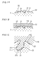
- the noble metal nuclei 92 can not enter the fine cavities 21 formed on the surface of the solid electrolyte 2, but stay at entrances of the fine cavities 21.
- the plating film 119 can not advance into the fine cavities 21 so that the adhesion force based on the anchor effect can not be achieved between the plating film 119 and the solid electrolyte 2.
- the noble metal nuclei 92 are localized on the surface of the solid electrolyte 2. This means that distances between the adjacent noble metal nuclei 92 become large. As appreciated, the adhesion force between the plating film 119 and the solid electrolyte 2 can not be achieved at portions where no noble metal nuclei 92 exist, and thus, in the latter forming method, those portions where the adhesion force can not be achieved exist largely on the surface of the solid electrolyte 2.
- an object of the present invention to provide an oxygen sensor element, wherein an electrode is hard to peel off from a solid electrolyte and the surface resistance at an interface between the electrode and the solid electrolyte is small.
- an oxygen sensor element comprises a solid electrolyte having cavities on a surface thereof; and an electrode formed on the surface of the solid electrolyte, the electrode deeply entering the cavities for ensuring adhesion of the electrode relative to the surface of the solid electrolyte.
- the electrode is in the form of a plating film produced via noble metal nuclei provided on the surface of the solid electrolyte, the noble metal nuclei having a mean particle diameter which is small enough for the noble metal nuclei to deeply enter the cavities.
- the mean particle diameter of the noble metal nuclei is 0.05 ⁇ m or smaller.
- Each of the cavities has finer cavities therein, and that the electrode further enters the finer cavities.
- a method of producing an oxygen sensor element which includes a solid electrolyte having cavities on a surface thereof and an electrode formed on the surface of the solid electrolyte, comprises the steps of: applying a solution containing a noble metal compound for nucleus formation to the surface at an electrode forming portion of the solid electrolyte to form a coating film; heat-treating the coating film by heating to form a nucleus forming portion where noble metal nuclei are deposited; plating the nucleus forming portion to form a plating film, the plating film deeply entering the cavities; and burning the plating film to form the electrode so that the electrode deeply enters the cavities.
- the noble metal nuclei have a mean particle diameter which is small enough for the noble metal nuclei to deeply enter the cavities.
- the mean particle diameter of the noble metal nuclei is 0.05 ⁇ m or smaller.
- the coating film is heat-treated at a temperature in the range of 200°C to 600°C.
- the noble metal compound is an organic noble metal compound.
- a concavo-convex treatment is applied to the surface of the solid electrolyte for promoting irregularities to be formed on the surface.
- a concentration of the noble metal compound relative to the solution is 0.05% by weight to 0.4% by weight.
- noble metal in the noble metal compound is at least one selected from the group consisting of Pt. Pd, Au and Rh.
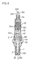
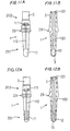
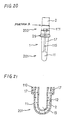
- an oxygen sensor element 1 includes a cylindrical solid electrolyte 2 and electrodes formed on the surface of the solid electrolyte 2.
- the electrodes include an external electrode 11 formed on an outer periphery of the solid electrolyte 2 and an internal electrode 12 formed on an inner periphery of the solid electrolyte 2.
- a solution containing a noble metal compound for nucleus formation is applied to electrode forming portions of the solid electrolyte 2 to form coating films.
- the coating films are subjected to heat treatment by heating so as to form nucleus forming portions 20 wherein noble metal nuclei 22 are deposited as shown in Fig. 1A (showing only one of the nucleus forming portions 20).
- the noble metal nuclei 22 are in the form of noble metal spheres or hemispheres obtained by decomposing the noble metal compound contained in the solution through the heat treatment of the coating films so as to deposit on the surface of the solid electrolyte 2.
- plating films 119 are burned to achieve the foregoing electrodes 11 and 12.
- the mean particle diameter of the noble metal nuclei 22 at the nucleus forming portions 20 is 0.05 ⁇ m or smaller.
- the solid electrolyte 2 is closed at its tip to provide a reference gas chamber 13.
- the solid electrolyte 2 is made of zirconia.
- the external electrode 11 is disposed on the outer periphery of the solid electrolyte 2 while the internal electrode 12 is disposed on the inner periphery thereof defining the reference gas chamber 13.
- a collar portion 29 protruding radially outward. At the upper side of the collar portion 29, two steps are formed to provide three diameter-different portions.
- the external electrode 11 is formed in a strip shape at a tip portion 201 of the solid electrolyte 2.
- the internal electrode 12 is formed on the inner periphery at a portion defining the reference gas chamber 13 and corresponding to the external electrode 11.
- the external electrode 11 is electrically connected to electrode terminals 111 via electrode leads 110 each extending upward from the external electrode 11.
- the internal electrode 12 is electrically connected to electrode terminals 121 via electrode leads 120 each extending upward from the internal electrode 12.
- the electrode terminals 111 and 121 are formed on the outer periphery of the solid electrolyte 2 at a trunk portion 202 thereof.
- the electrode terminals 121 may be formed on the inner periphery of the solid electrolyte 2.
- the external electrode 11, the electrode leads 110 and the electrode terminals 111 are formed integral with each other.
- the internal electrode 12, the electrode leads 120 and the electrode terminals 121 are formed integral with each other.
- the electrode leads 110 are provided in pair and the electrode leads 120 are also provided in pair.
- the electrode leads 110 and 120 are arranged in pairs in the same radial directions of the solid electrolyte 2 with a phase difference of 180°.
- the electrode leads 110 and 120 may be arranged in four different radial directions with phase differences of 90°. Further, the number of the electrode leads 110 or 120 may take a value other than two as long as the sensor output can be taken out.
- a length L1 of the external electrode 11 and a length L2 of the internal electrode 12 are set equal to each other, each being set to 10mm.
- a thickness of each of the electrodes 11 and 12 is set to 1 ⁇ m.
- Lead widths W1 and W2 of the electrode leads 110 and 120 are set to 1.5mm, respectively, a length R1 of the electrode lead 110 is set to 23mm, and a length R2 of the electrode lead 120 is set to 34mm.
- each of the electrode terminals 111 and 121 has a rectangular shape with 5mm by 4mm. On the other hand, the electrode terminal 111, 121 may take any shape as long as the sensor output can be taken out.
- the length L1, L2 is set to 2mm to 20mm. If the length L1, L2 is smaller than 2mm, it is possible that the required sensor output can not be achieved. On the other hand, if the length L1, L2 is greater than 20mm, it is possible that the sensor output includes an output from a portion (low temperature portion) whose response characteristic is poor so that the whole response characteristic is deteriorated. Further, the cost performance may be possibly lowered.
- the oxygen sensor 3 includes a housing 30 and the oxygen sensor element 1 received through the housing 30.
- a to-be-measured gas chamber 33 defined by a to-be-measured gas side cover 330 which is double-structured for protecting the tip portion 201 of the oxygen sensor element 1.
- a to-be-measured gas side cover 330 which is double-structured for protecting the tip portion 201 of the oxygen sensor element 1.
- three-stage atmosphere side covers 31, 32 and 33 are provided at the upper side of the housing 30.
- a rod-shaped heater 34 is received in the reference gas chamber 13 of the oxygen sensor element 1 with given clearances relative to the inner periphery of the solid electrolyte 2 defining the reference gas chamber 13.
- An elastic insulating member 39 with leads 391-393 passing therethrough is fitted into the atmosphere side cover 32 at its upper end.
- the leads 391 and 392 are for taking out a current generated through the solid electrolyte 2 as a signal and sending it out to the exterior.
- the lead 393 is for energizing the heater 34 to generate heat.
- terminals 383 and 384 which are electrically connected to terminals 381 and 382 fixed to the oxygen sensor element 1.
- the terminals 381 and 382 are in abutment with the foregoing electrode terminals 111 and 121 of the oxygen sensor element 1.
- each of the electrode forming portions of the solid electrolyte 2 includes not only a portion where the electrode 11, 12 is formed, but also those portions where the electrode leads 110, 120 and the electrode terminals 111, 121 are formed.
- zirconia is formed into a shape as shown in Figs. 2A and 2B and then provisionally burned to obtain the solid electrolyte 2 in the form of a zirconia sintered body (ZrO 2 -Y 2 O 3 ).
- the solid electrolyte 2 may be made of other materials as long as ionic conductivity is achieved.
- a solution containing a noble metal compound is applied to the electrode forming portions on the inner and outer peripheries of the solid electrolyte 2 to form coating films (see Figs. 2A and 2B).
- an organic platinum compound such as dibenzylidene platinum (C 16 H 16 Pt)
- the organic platinum compound is contained at 0.4% by weight.
- the solution contains an acrylic binder and terpineol.
- the dispenser method is used for applying the foregoing solution to the electrode forming portion on the inner periphery.
- the pad printing is carried out several times for applying the foregoing solution to the electrode forming portion on the outer periphery.
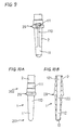
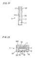
- a nozzle 4 having an inside passage and as shown in Figs. 4A and 4B is used.
- a tip portion 41 of the nozzle 4 is bent by an angle of about 90° and formed at its center with an injection hole 410 for injecting the solution.
- the nozzle 4 is inserted into the solid electrolyte 2 near the bottom of the reference gas chamber 13.
- the solution is applied to the electrode forming portion for one of the electrode leads 120.
- the solution is further applied while moving the tip portion 41 of the nozzle 4 vertically and circumferentially relative to the inner periphery of the solid electrolyte, so as to complete application of the solution for the internal electrode 12.
- the nozzle 4 is moved upward of the reference gas chamber 13. At this time, the tip portion 41 of the nozzle 4 is not moved circumferentially relative to the inner periphery of the solid electrolyte 2.
- the solution is applied to the electrode forming portion for lead portions 129 (see Fig. 2A) drawing out the corresponding electrode leads 120 to the outer periphery of the solid electrolyte 2 and for the electrode terminals 121 on the outer periphery of the solid electrolyte 2 near its upper end, and then the application of the solution is completed.
- a nozzle 4 shown in Figs. 5A and 5B may be used instead of the nozzle 4 shown in Figs. 4A and 4B.
- a tip portion of the nozzle 4 in Figs. 5A and 5B includes a porous member 42. Through pores of the porous member 42, the solution is injected and applied to the electrode forming portion.
- the coating films at the electrode forming portions are dried.
- the coating films are subjected to heat treatment at 400°C for decomposing the organic platinum compound contained in the coating films so as to deposit the noble metal nuclei, i.e. the platinum nuclei at the foregoing electrode forming portions, while removing the other components, such as the binder, through volatilization or decomposition.
- the nucleus forming portions 20 are formed wherein the noble metal nuclei 22 are uniformly dispersed and further deeply enter fine holes or cavities 21 which are formed in large number on the surface of the solid electrolyte 2.
- the plating film 119 may be made of noble metal, other than platinum, such as palladium (Pd), gold (Au) and rhodium (Rh). It is not necessary that the plating film is made of the same material as the noble metal nucleus.
- the noble metal nuclei 22 react with the noble metal contained in a plating liquid so as to facilitate formation of the plating films 119. Since the noble metal nuclei 22 deeply enter the fine cavities 21, the plating liquid and thus the plating films 119 also deeply enter the fine cavities 21. Thereafter, the plating films 119 together with the solid electrolyte 2 are burned at 1,000°C to achieve the external and internal electrodes 11 and 12, the electrode leads 110 and 120 and the electrode terminals 111 and 121 which also deeply enter the fine cavities 21.
- the oxygen sensor element 1 according to the first embodiment is obtained.
- the oxygen sensor element 1 has the following advantages:
- the mean particle diameter of the noble metal nuclei 22 produced through the foregoing operation is no greater than 0.05 ⁇ m which is much smaller as compared with the fine cavities 21. Accordingly, the noble metal nuclei 22 can deeply enter the fine cavities 21. Further, as best shown in Fig. 1C, the noble metal nuclei 22 can even enter finer holes or cavities 210 formed within the fine cavities 21.
- a distance d between the adjacent noble metal nuclei 22 is very small. This means that the noble metal nuclei 22 are not localized but dispersed uniformly over the electrode forming portions to form the nucleus forming portions 20.
- each of the plating films 119 formed on the nucleus forming portions 20 can be securely adhered to the solid electrolyte 2 based on a strong anchor effect achieved at an interface between the plating film 119 and the solid electrolyte 2. Accordingly, a strong adhesion force can be achieved between the solid electrolyte 2 and each of the external and internal electrodes 11 and 12 which are obtained by burning the plating films 119. Hence, the external and internal electrodes 11 and 12 are hard to peel off from the surface of the solid electrolyte 2.
- the noble metal nuclei 22 are dispersed uniformly all over the nucleus forming portions 20, the foregoing strong adhesion force is exerted all over the interface between the solid electrolyte 2 and each of the external and internal electrodes 11 and 12. Thus, the surface resistance at the interface therebetween is made small. This is also applied to the electrode leads 110 and 120 and the electrode terminals 111 and 121.
- the dispenser method and the pad printing are used for applying the solution to the electrode forming portions.
- it may be arranged to use at least one of the screen printing, the stamp printing, the roll transfer, the dip method and the spray method for applying the solution to the electrode forming portions.
- a coating film of a desired shape can be easily formed on a curved surface, such as the inner/outer periphery of the cylindrical solid electrolyte, and further a coating film can be formed with accuracy.
- the heat treatment to the coating films is performed at 400°C. It is preferable that the heat treatment to the coating films is performed at a temperature in the range of 200°C to 600°C.
- the heat treatment temperature is higher than 600°C
- flocculation of the noble metal is liable to occur so that the mean particle diameter of the noble metal nuclei may become greater than 0.05 ⁇ m.
- the noble metal nuclei may be localized. Accordingly, it is possible that the electrode is liable to peel off from the solid electrolyte.
- the heat treatment temperature is lower than 200°C
- it is possible that decomposition of the noble metal compound does not practically occur. Accordingly, deposition of the noble metal nuclei does not advance to disable formation of the nucleus forming portion.
- the plating film does not practically adhere to the solid electrolyte so that the solid electrolyte may be partially exposed to the exterior.
- those components, other than the noble metal compound, contained in the solution or carbon produced by those components remain on the surface of the solid electrolyte. In this case, the strong adhesion force between the noble metal nuclei and the solid electrolyte may not be achieved.
- the noble metal in the noble metal compound for nucleus formation is platinum. It is preferable that noble metal in a noble metal compound for nucleus formation is at least one selected from the group consisting of Pt, Pd, Au and Rh. These metals have a catalytic function for facilitating plating so that excellent plating is achieved on the solid electrolyte. Further, it is preferable to use an organic noble metal compound as the noble metal compound as in the foregoing first embodiment. The organic noble metal compound makes it easy to adjust viscosity of the solution. thereby making it easy to apply the solution to the electrode forming portion of the solid electrolyte.
- the organic platinum compound is contained in the solution at 0.4% by weight. It is preferable that the concentration of the noble metal compound relative to the solution is in the range of 0.05% by weight to 0.4% by weight.
- the concentration is smaller than 0.05% by weight, the amount of the noble metal compound is so small that it may be difficult to form an nucleus forming portion where the noble metal nuclei are uniformly dispersed. In this case, since the strong adhesion force can not be achieved between the plating film and the solid electrolyte, the electrode may be liable to peel off from the solid electrode.
- the concentration exceeds 0.4% by weight
- flocculation of the noble metal may be liable to occur to increase the mean particle diameter of the noble metal nuclei to be greater than 0.05 ⁇ m.
- the noble metal nuclei may be localized. Accordingly, it is possible that the electrode is liable to peel off from the solid electrolyte.
- Table 1 relates to inventive samples 1-19 while Table 2 relates to comparative samples 20-28.
- organic noble metal compounds were used as noble metal compounds.
- dibenzylidene platinum C 16 H 16 Pt
- noble metal was Pd
- samples 1-28 The evaluation of samples 1-28 was carried out based on a resistance value test and a peeling test.
- a resistance value of each sample was obtained by measuring a dc resistance between the external and internal electrodes at 400°C.
- the peeling test was carried out by adhering an adhesive tape to the external electrode and then peeling off the tape. After peeling off the tape, macro-observation and micro-observation of the external electrode were performed. If no peeling of the external electrode was observed both in macro-observation and micro-observation, O was indicated in Table 1 and Table 2.
- the macro-observation was performed using a magnifying glass, while the micro-observation was performed using a scanning electron microscope.
- inventive samples 1-19 all showed low resistance values, meaning that the surface resistances thereof were small. Thus, each inventive sample can ensure an output necessary for detection of the oxygen concentration. As seen from Table 1, the results of the peeling test were also excellent in all inventive samples 1-19.
- an inorganic noble metal compound can also be used as a noble metal compound.
- the concentration of noble metal in a solution was 0.4% by weight and the heat treatment temperature was 400°C.
- inventive samples 1-19 in Table 1 both showed low resistance values, and the results of the peeling test thereof were also excellent.
- the solid electrolyte 2 of the oxygen sensor element 1 is formed with two steps at the upper side of the collar portion 29 as shown in Figs. 2A and 2B.
- a solid electrolyte 2 having only one step at the upper side of a collar portion 29 may also be used.
- a solid electrolyte having no step may also be used.
- Figs. 10A and 10B show a modification of the oxygen sensor element according to the foregoing first embodiment, wherein a configuration of each of electrode forming portions on a solid electrolyte 2 differs from that of the foregoing first embodiment.
- a plating film is formed on the outer periphery of the solid electrolyte 2 over a wide range including a tip portion 201 and a trunk portion 202 so as to form a cup-shaped external electrode 11, a cylindrical electrode lead 110 and a cylindrical electrode terminal 111.
- a plating film is formed all over the inner periphery of the solid electrolyte 2 so as to form a cup-shaped internal electrode 12, a cylindrical electrode lead 120 and a cylindrical electrode terminal 121.
- the other structure is the same as the foregoing first embodiment.
- Figs. 11A and 11B show a modification of the oxygen sensor element according to the foregoing first embodiment, wherein a configuration of each of electrode forming portions on a solid electrolyte 2 slightly differs from that of the foregoing first embodiment.
- an external electrode 11 covers the whole of a tip portion 201 of the solid electrolyte 2 on the outer periphery thereof as opposed to the foregoing first embodiment.
- an internal electrode 12 covers the whole of the tip portion 201 on the inner periphery thereof, and further, electrode terminals 121 are formed on the inner periphery of the solid electrolyte 2.
- the other structure is the same as the foregoing first embodiment.
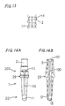
- Figs. 12A, 12B and 13 show a modification of the oxygen sensor element according to the foregoing first embodiment, wherein a configuration of each of electrode forming portions on a solid electrolyte 2 slightly differs from that of the foregoing first embodiment.
- an external electrode 11 is formed into a mesh shape.
- an internal electrode 12 is also formed into a mesh shape, and further, electrode terminals 121 are formed on the inner periphery of the solid electrolyte 2.
- the other structure is the same as the foregoing first embodiment.
- Figs. 14A and 14B show a modification of the oxygen sensor element according to the foregoing first embodiment, wherein a configuration of each of electrode forming portions on a solid electrolyte 2 slightly differs from that of the foregoing first embodiment.
- a length of each of an external electrode 11 and an internal electrode 12 is set approximately half the length L1, L2 of the electrode 11, 12 in the foregoing first embodiment, and further, electrode terminals 121 are formed on the inner periphery of the solid electrolyte 2.
- the other structure is the same as the foregoing first embodiment.
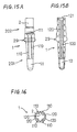
- Figs. 15A, 15B and 16 show a modification of the oxygen sensor element according to the foregoing first embodiment, wherein a configuration of each of electrode forming portions on a solid electrolyte 2 differs from that of the foregoing first embodiment.
- the number of electrode leads 110 extending from an external electrode 11 is four, and similarly, the number of electrode leads 120 extending from an internal electrode 12 is also four, and further, electrode terminals 121 are formed on the inner periphery of the solid electrolyte 2.
- the other structure is the same as the foregoing first embodiment.
- the masking operation can be partly omitted upon formation of the nucleus forming portions so that production of the oxygen sensor element can be facilitated.
- the improvement in oxygen diffusion can be achieved when only one of the external electrode 11 and the internal electrode 12 is formed into the mesh shape.
- the amount of the noble metal to be used can be reduced.
- an oxygen sensor element 1 includes an external electrode 11 and an internal electrode 12 similar to those in the modification shown in Figs. 11A and 11B. Further, a first protective layer 191 is formed on the external electrode 11 so as to cover the whole of the external electrode 11.
- the first protective layer 191 also has a function of a diffusion resistance layer.
- the first protective layer 191 has a thickness of 100 ⁇ m and a porosity of 20% and is formed of MgAl 2 O 4 spinel through plasma spraying.
- the other structure is the same as the foregoing first embodiment.
- the oxygen sensor element 1 is excellent in durability of the external electrode 11.
- Fig. 18 shows a modification of the oxygen sensor element according to the foregoing second embodiment.
- the oxygen sensor element 1 further includes a second protective layer 192 formed on the first protective layer 191.
- the second protective layer 192 has a thickness of 120 ⁇ m and a porosity of 20% to 50% and is made of Al 2 O 3 .
- the second protective layer 192 can be formed by slurrying Al 2 O 3 , coating the surface of the first protective layer 191 with slurried Al 2 O 3 using the dip method, and then applying heat treatment thereto.
- the other structure is the same as the foregoing second embodiment.
- the oxygen sensor element 1 is further excellent in durability of the external electrode 11.
- a concavo-convex treatment is applied to the surface of the solid electrolyte 2 for promoting irregularities to be formed thereon. Since the irregularities are promoted on the surface of the solid electrolyte 2 through the concavo-convex treatment, contact areas between the solid electrolyte 2 and the plating film can be increased, more noble metal nuclei can be in abutment with the plating film, and the plating film can deeply engage with the irregularities on the surface of the solid electrolyte 2. Thus, a strong adhesion force can be exerted between the solid electrolyte 2 and the plating film and thus the electrode. As seen from Fig.
- the irregularities on the surface of the solid electrolyte 2 can increase not only an adhesive force between the solid electrolyte 2 and the external electrode 11, but also an adhesive force between the external electrode 11 and the first protective layer 191.
- the oxygen sensor element 1 having excellent durability can be achieved.
- the foregoing concavo-convex treatment can be performed by etching. powder application, thermal spraying or the like.
- an oxygen sensor element 1 includes an insulating layer 17.
- a nucleus forming portion is formed on the outer periphery of a solid electrolyte 2 in a range up to a portion A at a trunk portion 202 from the tip of a tip portion 201. and then a plating film is formed on the nucleus forming portion.
- the insulating layer 17 made of MgAl 2 O 4 spinel or Al 2 O 3 is formed on the plating film at portions other than the tip portion 201 working as the external electrode 11.
- electrode leads 110 and electrode terminals 111 are formed on the insulating layer 17 so as to be electrically connected to the plating film at the tip portion 201 (see Fig. 21).
- the other structure is the same as the foregoing first embodiment.
- the fourth embodiment relates to a stacked oxygen sensor element 5.
- the stacked oxygen sensor element 5 includes a plate solid electrolyte 2 provided with an external electrode 11 and an internal electrode 12.
- the external electrode 11 and the internal electrode 12 are obtained in the same manner as in the foregoing first embodiment, that is, by forming nucleus forming portions on electrode forming portions of the plate solid electrolyte 2, then forming plating films on the nucleus forming portions and burning the plating films.
- first and second protective layers 191 and 192 are formed in the order named.
- a heater board 59 having an atmosphere introducing duct and heaters 58 is arranged on the inner side of the solid electrolyte 2 where the internal electrode 12 is formed.
- the heater board 59 is a ceramic sheet of Al 2 O 3 formed by press forming, injection molding, sheet forming, lamination or the like.
- the external electrode 11 is electrically connected via an electrode lead 110 to an electrode terminal 111 exposed to the exterior.
- the internal electrode 12 is electrically connected via an electrode lead 120 to an electrode terminal 121 exposed to the exterior.
- the electrode terminals 111 and 121 are formed on an outer surface of the oxygen sensor element 5.
- the other structure is the same as the foregoing first embodiment.
- the present invention is also applicable to the stacked oxygen sensor element 5.
- the stacked oxygen sensor element 5 in this embodiment achieves effects similar to those of the foregoing first embodiment.
- the present invention is further applicable to, for example, a two-cell type stacked oxygen sensor element where electrodes are provided relative to a plurality of solid electrolytes.
Landscapes
- Chemical & Material Sciences (AREA)
- Life Sciences & Earth Sciences (AREA)
- Health & Medical Sciences (AREA)
- Physics & Mathematics (AREA)
- Chemical Kinetics & Catalysis (AREA)
- Electrochemistry (AREA)
- Molecular Biology (AREA)
- Analytical Chemistry (AREA)
- Biochemistry (AREA)
- General Health & Medical Sciences (AREA)
- General Physics & Mathematics (AREA)
- Immunology (AREA)
- Pathology (AREA)
- Measuring Oxygen Concentration In Cells (AREA)
Description
| SAMPLE NO. | NOBLE METAL | NOBLE METAL NUCLEUS MEAN PARTICLE DIAMETER (µm) | NOBLE METAL CONCENTRATION (% by weight) | HEAT TREATMENT TEMP. (°C) | RESISTANCE VALUE (KΩ) | |
| 1 | Pt | 0.01 | 0.4 | 400 | 9 | |
| 2 | Pt | 0.007 | 0.1 | 200 | 10 | O |
| 3 | Pt | 0.01 | 0.05 | 600 | 9 | |
| 4 | Pt | 0.005 | 0.05 | 200 | 10 | |
| 5 | Pt | 0.04 | 0.4 | 400 | 11 | O |
| 6 | Pt | 0.03 | 0.1 | 600 | 9 | O |
| 7 | Pt | 0.006 | 0.1 | 200 | 11 | O |
| 8 | Pt | 0.008 | 0.05 | 400 | 10 | O |
| 9 | Pt | 0.08 | 0.4 | 600 | 11 | O |
| 10 | Pd | 0.008 | 0.4 | 200 | 11 | |
| 11 | Pd | 0.01 | 0.1 | 400 | 10 | |
| 12 | Pd | 0.01 | 0.05 | 600 | 10 | |
| 13 | Pd | 0.005 | 0.05 | 200 | 9 | O |
| 14 | Pd | 0.03 | 0.4 | 400 | 10 | O |
| 15 | Pd | 0.05 | 0.1 | 600 | 9 | O |
| 16 | Pd | 0.007 | 0.1 | 200 | 10 | |
| 17 | Pd | 0.01 | 0.06 | 400 | 10 | O |
| 18 | Pd | 0.09 | 0.4 | 600 | 12 | O |
| 19 | Rh | 0.01 | 0.4 | 400 | 10 | O |
| SAMPLE NO. | NOBLE METAL | NOBLE METAL NUCLEUS MEAN PARTICLE DIAMETER (µM) | NOBLE METAL CONCENTRATION (% by weight) | HEAT TREATMENT TEMP. (°C) | RESISTANCE VALUE (kΩ) | |
| 20 | Pt | 0.4 | 100 | X | ||
| 21 | Pt | 0.11 | 0.4 | 700 | 32 | X |
| 22 | Pd | 0.15 | 0.4 | 900 | X | |
| 23 | Pd | 0.4 | 100 | X | ||
| 24 | Pd | 0.12 | 0.4 | 700 | 96 | X |
| 25 | Pt | 0.18 | 0.4 | 900 | X | |
| 26 | Pt | 0.001 | 0.01 | 600 | X | |
| 27 | Pt | 0.12 | 0.6 | 600 | 30 | X |
| 28 | Rh | 0.15 | 0.4 | 900 | X |
| SAMPLE NO. | NOBLE METAL COMPOUND | NOBLE METAL NUCLEUS MEAN PARTICLE DIAMETER (µM) | RESISTANCE VALUE (kΩ) | PEELING TEST |
| 29 | H2PtCl6 | 0.005 | 9 | |
| 30 | Pt PARTICLES | 0.05 | 12 | O |
Claims (7)
- An oxygen sensor element (1) comprising:characterized in that said noble metal nuclei (22) have mean particle diameters of no greater than 0.05 µm and are provided further in said finer cavities so that said electrode is provided in said cavities and further in said finer cavities for ensuring adhesion of said electrode relative to the surface of said solid electrolyte (2).a solid electrolyte (2) having cavities on a surface thereof, each said cavities having finer cavities therein; andan electrode formed on the surface of said solid electrolyte (2) in the form of a plating film produced via noble metal nuclei (22), said noble metal nuclei (22) being provided on the surface of said solid electrolyte (2) so as to be located in said cavities,
- A method of producing an oxygen sensor element which includes a solid electrolyte (2) having cavities on a surface thereof and an electrode formed on the surface of said solid electrolyte (2), each of said cavities having finer cavities therein, said method comprising the steps of:applying a solution containing a noble metal compound for nucleus formation to said surface at an electrode forming portion of said solid electrolyte to form a coating film;heat-treating said coating film by heating to form a nucleus forming portion where noble metal nuclei (22) are deposited, said nucleus forming portion is provided in said cavities, said noble metal nuclei (22) have mean particle diameters of no greater than 0.05 µm so that said noble metal nuclei (22) enter in said finer cavities;plating said nucleus forming portion to form a plating film (119) thereon; andburning said plating film (119) to form said electrode so that said electrode enters said cavities and further enters said finer cavities for ensuring adhesion of said electrode relative to the surface of said solid electrode (2).
- The method according to claim 2, wherein said coating film is heat-treated at a temperature in the range of 200 °C to 600 °C.
- The method according to claim 2, wherein said noble metal compound is an organic noble metal compound.
- The method according to claim 2, further comprising the step of making irregular the surface of said solid electrolyte (2) so that irregularities are formed on the surface thereof.
- The method according to claim 2, wherein a concentration of said noble metal compound relative to said solution is 0.05% by weight to 0.4% by weight.
- The method according to claim 2, wherein noble metal in said noble metal compound is at least one selected from the group consisting of Pt, Pd, Au and Rh.
Applications Claiming Priority (3)
| Application Number | Priority Date | Filing Date | Title |
|---|---|---|---|
| JP150255/96 | 1996-05-21 | ||
| JP15025596A JP3811991B2 (en) | 1996-05-21 | 1996-05-21 | Oxygen sensor element manufacturing method and oxygen sensor element |
| JP15025596 | 1996-05-21 |
Publications (3)
| Publication Number | Publication Date |
|---|---|
| EP0809101A2 EP0809101A2 (en) | 1997-11-26 |
| EP0809101A3 EP0809101A3 (en) | 1999-11-10 |
| EP0809101B1 true EP0809101B1 (en) | 2004-02-04 |
Family
ID=15492953
Family Applications (1)
| Application Number | Title | Priority Date | Filing Date |
|---|---|---|---|
| EP97108239A Expired - Lifetime EP0809101B1 (en) | 1996-05-21 | 1997-05-21 | Oxygen sensor element and method of producing same |
Country Status (6)
| Country | Link |
|---|---|
| US (2) | US5948225A (en) |
| EP (1) | EP0809101B1 (en) |
| JP (1) | JP3811991B2 (en) |
| KR (1) | KR100230601B1 (en) |
| CN (1) | CN1122841C (en) |
| DE (1) | DE69727420T2 (en) |
Families Citing this family (34)
| Publication number | Priority date | Publication date | Assignee | Title |
|---|---|---|---|---|
| JP3532366B2 (en) * | 1996-11-18 | 2004-05-31 | 日本特殊陶業株式会社 | Heat-resistant metal sheath lead wire for sensor |
| JP3605984B2 (en) * | 1997-01-23 | 2004-12-22 | 株式会社デンソー | Method and apparatus for manufacturing oxygen sensor element |
| JP3956435B2 (en) | 1997-08-07 | 2007-08-08 | 株式会社デンソー | Oxygen sensor element |
| US6315880B1 (en) | 1997-10-16 | 2001-11-13 | Mary R. Reidmeyer | Chemical plating method, electrolytic cell and automotive oxygen sensor using it |
| EP1195602A1 (en) * | 1997-11-20 | 2002-04-10 | Denso Corporation | Oxygen sensor with the heater element contacting the inner surface of the closed end tubular solid electrolyte |
| JP3643224B2 (en) * | 1997-11-25 | 2005-04-27 | 日本特殊陶業株式会社 | Sensor element electrode forming method |
| JP3541702B2 (en) * | 1998-01-16 | 2004-07-14 | 株式会社デンソー | Ceramic-metal bonded body and method of manufacturing the same |
| JP3994561B2 (en) * | 1998-08-12 | 2007-10-24 | 株式会社デンソー | Gas sensor |
| JP2002048758A (en) * | 2000-07-31 | 2002-02-15 | Denso Corp | Gas sensor element and its manufacturing method |
| JP4617599B2 (en) * | 2000-08-07 | 2011-01-26 | 株式会社デンソー | Gas sensor element and manufacturing method thereof |
| JP2003107033A (en) * | 2001-07-27 | 2003-04-09 | Denso Corp | Gas sensor |
| JP4204773B2 (en) * | 2001-09-17 | 2009-01-07 | 株式会社日立製作所 | Air-fuel ratio detection device |
| EP1354637B1 (en) * | 2002-04-17 | 2012-04-25 | Denso Corporation | Active liquid applicator for forming active film |
| US7399501B2 (en) * | 2002-11-06 | 2008-07-15 | Ngk Spark Plug Co., Ltd. | Gas sensor manufacturing process |
| US8906214B2 (en) * | 2003-02-10 | 2014-12-09 | Robert Bosch Gmbh | Contamination-resistant gas sensor element |
| US7211180B2 (en) * | 2003-02-10 | 2007-05-01 | Robert Bosch Corporation | Contamination-resistant gas sensor element |
| US20090101502A1 (en) * | 2003-02-10 | 2009-04-23 | Robert Bosch Gmbh | Thermal Shock Resistant Gas Sensor Element |
| US6843105B1 (en) * | 2003-06-30 | 2005-01-18 | Robert Bosch Corporation | Contact pin for exhaust gas sensor |
| JP4194452B2 (en) * | 2003-08-29 | 2008-12-10 | 新日本製鐵株式会社 | Equipment for measuring oxygen concentration in high-temperature gas |
| US7404883B2 (en) | 2004-04-12 | 2008-07-29 | Robert Bosch Gmbh | Insulation bushing assembly for an exhaust gas sensor |
| US20060228495A1 (en) * | 2005-04-12 | 2006-10-12 | Robert Bosch Gmbh | Method of manufacturing an exhaust gas sensor |
| JP2007248123A (en) * | 2006-03-14 | 2007-09-27 | Ngk Spark Plug Co Ltd | Gas sensor element and gas sensor manufacturing method |
| JP2009115776A (en) * | 2007-07-11 | 2009-05-28 | Ngk Spark Plug Co Ltd | Ammonia gas sensor |
| JP5187417B2 (en) * | 2010-09-10 | 2013-04-24 | 株式会社デンソー | Gas sensor element and manufacturing method thereof |
| US9297791B2 (en) | 2012-12-20 | 2016-03-29 | Robert Bosch Gmbh | Gas sensor with thermal shock protection |
| JP6104137B2 (en) * | 2013-02-14 | 2017-03-29 | 日本特殊陶業株式会社 | Method for manufacturing gas sensor element |
| JP6359373B2 (en) * | 2013-09-05 | 2018-07-18 | 日本特殊陶業株式会社 | Gas sensor element and gas sensor |
| JP6003928B2 (en) * | 2014-03-04 | 2016-10-05 | 株式会社デンソー | Gas sensor element, method of manufacturing the same, and gas sensor |
| JP6350326B2 (en) | 2014-06-30 | 2018-07-04 | 株式会社デンソー | Gas sensor |
| JP6596809B2 (en) | 2014-06-30 | 2019-10-30 | 株式会社デンソー | Gas sensor element |
| JP6398741B2 (en) * | 2015-01-20 | 2018-10-03 | 株式会社デンソー | Gas sensor element manufacturing method and active solution dropping device |
| JP6796403B2 (en) * | 2016-06-20 | 2020-12-09 | 日本特殊陶業株式会社 | Sensor |
| JP2018009817A (en) | 2016-07-11 | 2018-01-18 | 株式会社デンソー | Gas sensor |
| JP2020094831A (en) * | 2018-12-10 | 2020-06-18 | 日本特殊陶業株式会社 | Manufacturing method for gas sensor element, gas sensor element, and gas sensor |
Family Cites Families (24)
| Publication number | Priority date | Publication date | Assignee | Title |
|---|---|---|---|---|
| US3978006A (en) * | 1972-02-10 | 1976-08-31 | Robert Bosch G.M.B.H. | Methods for producing oxygen-sensing element, particularly for use with internal combustion engine exhaust emission analysis |
| JPS5033892A (en) * | 1973-07-24 | 1975-04-01 | ||
| JPS5315886A (en) * | 1976-07-28 | 1978-02-14 | Nippon Denso Co Ltd | Oxygen concentration detector |
| JPS53100890A (en) * | 1977-02-16 | 1978-09-02 | Ngk Insulators Ltd | Oxygen concentration cell and its manufacture |
| DE2830778C2 (en) * | 1978-07-13 | 1985-10-31 | Robert Bosch Gmbh, 7000 Stuttgart | Electrochemical measuring sensor with improved adhesive strength of the electrode system on the solid electrolyte |
| US4199425A (en) * | 1978-11-30 | 1980-04-22 | General Motors Corporation | Solid electrolyte exhaust gas sensor with increased NOx sensitivity |
| JPS5692447A (en) * | 1979-12-26 | 1981-07-27 | Nissan Motor Co Ltd | Production of film-structure oxygen sensor element |
| JPS56160653A (en) * | 1980-05-14 | 1981-12-10 | Ngk Spark Plug Co Ltd | Manufacture of oxygen concentration cell |
| US4374876A (en) * | 1981-06-02 | 1983-02-22 | Occidental Chemical Corporation | Process for the immersion deposition of gold |
| US4418099A (en) * | 1982-02-05 | 1983-11-29 | Engelhard Corporation | Non-burnished precious metal composition |
| US4477481A (en) * | 1982-06-24 | 1984-10-16 | General Foods Corporation | Method for producing dried citrus pulp |
| US4506485A (en) * | 1983-04-12 | 1985-03-26 | State Of California, Department Of Transportation | Process for inhibiting corrosion of metal embedded in concrete and a reinforced concrete construction |
| JPH0694592B2 (en) * | 1986-04-22 | 1994-11-24 | 日産化学工業株式会社 | Electroless plating method |
| US4863893A (en) * | 1986-08-06 | 1989-09-05 | Engelhard Corporation | Low temperature light off ammonia oxidation |
| JPH0731150B2 (en) * | 1987-02-16 | 1995-04-10 | 日本碍子株式会社 | Oxygen sensor element and manufacturing method thereof |
| JPH01184457A (en) * | 1988-01-18 | 1989-07-24 | Ngk Insulators Ltd | Oxygen sensor element |
| JPH0216442A (en) * | 1988-07-04 | 1990-01-19 | Mitsubishi Motors Corp | Oxygen sensor |
| JPH0495766A (en) * | 1990-08-06 | 1992-03-27 | Ngk Spark Plug Co Ltd | Manufacture of oxygen sensor |
| JP3003956B2 (en) * | 1991-03-20 | 2000-01-31 | 日本特殊陶業株式会社 | Oxygen sensor and method of manufacturing the same |
| US5281635A (en) * | 1991-05-17 | 1994-01-25 | Johnson Matthey Public Limited Company | Precious metal composition |
| JP3443962B2 (en) * | 1993-09-14 | 2003-09-08 | 株式会社デンソー | Oxygen concentration detector and manufacturing method thereof |
| US5593558A (en) * | 1994-06-09 | 1997-01-14 | Nippondenso Co., Ltd. | Oxygen concentration detector |
| JP3424356B2 (en) * | 1994-10-28 | 2003-07-07 | 株式会社デンソー | Oxygen sensor element and manufacturing method thereof |
| JPH08166369A (en) * | 1994-12-13 | 1996-06-25 | Nippondenso Co Ltd | Oxygen sensor element and manufacture thereof |
-
1996
- 1996-05-21 JP JP15025596A patent/JP3811991B2/en not_active Expired - Fee Related
-
1997
- 1997-05-20 KR KR1019970019573A patent/KR100230601B1/en not_active Expired - Fee Related
- 1997-05-21 EP EP97108239A patent/EP0809101B1/en not_active Expired - Lifetime
- 1997-05-21 CN CN97114948.8A patent/CN1122841C/en not_active Expired - Fee Related
- 1997-05-21 US US08/861,226 patent/US5948225A/en not_active Expired - Lifetime
- 1997-05-21 DE DE69727420T patent/DE69727420T2/en not_active Expired - Lifetime
-
1999
- 1999-07-26 US US09/360,147 patent/US6254926B1/en not_active Expired - Lifetime
Also Published As
| Publication number | Publication date |
|---|---|
| DE69727420T2 (en) | 2004-12-16 |
| EP0809101A2 (en) | 1997-11-26 |
| DE69727420D1 (en) | 2004-03-11 |
| US5948225A (en) | 1999-09-07 |
| US6254926B1 (en) | 2001-07-03 |
| JPH09304334A (en) | 1997-11-28 |
| CN1122841C (en) | 2003-10-01 |
| JP3811991B2 (en) | 2006-08-23 |
| EP0809101A3 (en) | 1999-11-10 |
| CN1174994A (en) | 1998-03-04 |
| KR100230601B1 (en) | 1999-12-01 |
Similar Documents
| Publication | Publication Date | Title |
|---|---|---|
| EP0809101B1 (en) | Oxygen sensor element and method of producing same | |
| US6395161B1 (en) | Gas sensor and corresponding production method | |
| US8414752B2 (en) | Multilayer ceramic NOx gas sensor device | |
| EP1195601B1 (en) | Oxygen sensor element and manufacturing method thereof | |
| EP1178303A2 (en) | Gas sensor element and manufacturing method thereof | |
| EP0345770B1 (en) | Gas sensor for measuring airfuel ratio and method of manufacturing the gas sensor | |
| US20020108853A1 (en) | Method for controlled deposition of lead oxide onto sensor element using a lead composition glass carrier | |
| US4265724A (en) | Electrochemical sensor, particularly oxygen sensor to determine exhaust gas composition from automotive internal combustion engines | |
| US6344118B1 (en) | Structure of oxygen sensing element | |
| US4650697A (en) | Process of manufacturing oxygen sensor | |
| EP0924515B1 (en) | Solid electrolyte with inner reference chamber and electrodes on inner and outer surfaces | |
| CA1085924A (en) | Solid electrolyte gas sensor having a protective bonding layer | |
| US20020102349A1 (en) | Low-density coating for gas sensors | |
| EP0059933A1 (en) | Solid electrolyte oxygen sensing element of laminated structure with gas diffusion layer on outer electrode | |
| US6572747B1 (en) | Method for making a wide range sensor element | |
| EP1234172A2 (en) | Method and device for pumping oxygen into a gas sensor | |
| US6797138B1 (en) | Gas senior design and method for forming the same | |
| US6196049B1 (en) | Sensing element and method for manufacturing a sensing element | |
| US5969232A (en) | Catalytic layer system | |
| JP2612584B2 (en) | Manufacturing method of oxygen detection element | |
| JP4637375B2 (en) | Manufacturing method of oxygen sensor | |
| JP3577816B2 (en) | Method for manufacturing oxygen sensor element | |
| JP4689860B2 (en) | Heater integrated oxygen sensor element | |
| US5202154A (en) | Method of producing thick-film gas sensor element having improved stability | |
| US20020100688A1 (en) | Gas sensor with selective reference electrode and method of making and using the same |
Legal Events
| Date | Code | Title | Description |
|---|---|---|---|
| PUAI | Public reference made under article 153(3) epc to a published international application that has entered the european phase |
Free format text: ORIGINAL CODE: 0009012 |
|
| AK | Designated contracting states |
Kind code of ref document: A2 Designated state(s): DE FR GB |
|
| PUAL | Search report despatched |
Free format text: ORIGINAL CODE: 0009013 |
|
| AK | Designated contracting states |
Kind code of ref document: A3 Designated state(s): DE FR GB |
|
| 17P | Request for examination filed |
Effective date: 20000117 |
|
| 17Q | First examination report despatched |
Effective date: 20020228 |
|
| GRAP | Despatch of communication of intention to grant a patent |
Free format text: ORIGINAL CODE: EPIDOSNIGR1 |
|
| GRAS | Grant fee paid |
Free format text: ORIGINAL CODE: EPIDOSNIGR3 |
|
| GRAA | (expected) grant |
Free format text: ORIGINAL CODE: 0009210 |
|
| AK | Designated contracting states |
Kind code of ref document: B1 Designated state(s): DE FR GB |
|
| REG | Reference to a national code |
Ref country code: GB Ref legal event code: FG4D |
|
| REF | Corresponds to: |
Ref document number: 69727420 Country of ref document: DE Date of ref document: 20040311 Kind code of ref document: P |
|
| ET | Fr: translation filed | ||
| PLBE | No opposition filed within time limit |
Free format text: ORIGINAL CODE: 0009261 |
|
| STAA | Information on the status of an ep patent application or granted ep patent |
Free format text: STATUS: NO OPPOSITION FILED WITHIN TIME LIMIT |
|
| 26N | No opposition filed |
Effective date: 20041105 |
|
| PGFP | Annual fee paid to national office [announced via postgrant information from national office to epo] |
Ref country code: GB Payment date: 20140521 Year of fee payment: 18 |
|
| PGFP | Annual fee paid to national office [announced via postgrant information from national office to epo] |
Ref country code: DE Payment date: 20140521 Year of fee payment: 18 Ref country code: FR Payment date: 20140527 Year of fee payment: 18 |
|
| REG | Reference to a national code |
Ref country code: DE Ref legal event code: R119 Ref document number: 69727420 Country of ref document: DE |
|
| GBPC | Gb: european patent ceased through non-payment of renewal fee |
Effective date: 20150521 |
|
| REG | Reference to a national code |
Ref country code: FR Ref legal event code: ST Effective date: 20160129 |
|
| PG25 | Lapsed in a contracting state [announced via postgrant information from national office to epo] |
Ref country code: DE Free format text: LAPSE BECAUSE OF NON-PAYMENT OF DUE FEES Effective date: 20151201 Ref country code: GB Free format text: LAPSE BECAUSE OF NON-PAYMENT OF DUE FEES Effective date: 20150521 |
|
| PG25 | Lapsed in a contracting state [announced via postgrant information from national office to epo] |
Ref country code: FR Free format text: LAPSE BECAUSE OF NON-PAYMENT OF DUE FEES Effective date: 20150601 |