EP0936404A2 - Dampferzeuger mit mehreren Rohrbündeln - Google Patents
Dampferzeuger mit mehreren Rohrbündeln Download PDFInfo
- Publication number
- EP0936404A2 EP0936404A2 EP99102429A EP99102429A EP0936404A2 EP 0936404 A2 EP0936404 A2 EP 0936404A2 EP 99102429 A EP99102429 A EP 99102429A EP 99102429 A EP99102429 A EP 99102429A EP 0936404 A2 EP0936404 A2 EP 0936404A2
- Authority
- EP
- European Patent Office
- Prior art keywords
- flue gas
- pipes
- steam
- distributor
- evaporator
- Prior art date
- Legal status (The legal status is an assumption and is not a legal conclusion. Google has not performed a legal analysis and makes no representation as to the accuracy of the status listed.)
- Withdrawn
Links
Images

Classifications
-
- F—MECHANICAL ENGINEERING; LIGHTING; HEATING; WEAPONS; BLASTING
- F22—STEAM GENERATION
- F22B—METHODS OF STEAM GENERATION; STEAM BOILERS
- F22B1/00—Methods of steam generation characterised by form of heating method
- F22B1/02—Methods of steam generation characterised by form of heating method by exploitation of the heat content of hot heat carriers
- F22B1/18—Methods of steam generation characterised by form of heating method by exploitation of the heat content of hot heat carriers the heat carrier being a hot gas, e.g. waste gas such as exhaust gas of internal-combustion engines
- F22B1/1807—Methods of steam generation characterised by form of heating method by exploitation of the heat content of hot heat carriers the heat carrier being a hot gas, e.g. waste gas such as exhaust gas of internal-combustion engines using the exhaust gases of combustion engines
- F22B1/1815—Methods of steam generation characterised by form of heating method by exploitation of the heat content of hot heat carriers the heat carrier being a hot gas, e.g. waste gas such as exhaust gas of internal-combustion engines using the exhaust gases of combustion engines using the exhaust gases of gas-turbines
-
- F—MECHANICAL ENGINEERING; LIGHTING; HEATING; WEAPONS; BLASTING
- F22—STEAM GENERATION
- F22B—METHODS OF STEAM GENERATION; STEAM BOILERS
- F22B37/00—Component parts or details of steam boilers
- F22B37/02—Component parts or details of steam boilers applicable to more than one kind or type of steam boiler
- F22B37/10—Water tubes; Accessories therefor
- F22B37/14—Supply mains, e.g. rising mains, down-comers, in connection with water tubes
Definitions
- the invention relates to a steam generator with several in a flue gas duct through which flue gas flows Pipe bundles with the characteristics of the generic term of Claim.
- the invention has for its object the generic To design steam generator so that in the presence of a uneven loading of the evaporator tubes constructive effort of the steam generator is reduced.
- This task becomes a generic steam generator according to the invention by the characterizing features of Claim resolved.
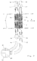
- a flue gas duct 1, for example, at the gas outlet Gas turbine can be connected through duct walls 2 limited.
- the flue gas duct 1 is in the direction of the arrows 3 from a flue gas or flows through the turbine exhaust gas.
- To the Flue gas duct 1 connects to a chimney 4 through which the Flue gases are removed.
- Fig. 1 are in the flue gas channel 1 in the direction of flow Flue gas a high pressure superheater 5, one Medium pressure reheater 6, a high pressure evaporator 7, a high pressure preheater 8, a medium pressure evaporator 9 and one Medium pressure preheater 10 is provided.
- a high pressure superheater 5 one Medium pressure reheater 6, a high pressure evaporator 7, a high pressure preheater 8, a medium pressure evaporator 9 and one Medium pressure preheater 10 is provided.
- These are tube bundles arranged vertically in a horizontal flue gas duct 1.
- the invention described below can also be used in one vertical flue gas duct 1 with horizontally arranged Pipe bundles can be realized.
- the high-pressure circuit is considered below. The same arrangement is also on the medium pressure circuit applicable.
- the High pressure preheater fed 8 feed water Via a high-pressure feed pump 11, the High pressure preheater fed 8 feed water. That in Heat exchange with the flue gas preheated feed water arrives after exiting the high pressure preheater 8 into one Distributor 12, from which it is connected via connecting pipes 13, 14 the tubes of the switched as a high pressure evaporator 7 Tube bundle. That evaporated in the high pressure evaporator 7 Water is fed to the high-pressure superheater 5 as steam.
- the superheated high pressure steam is on a not shown High pressure steam turbine given.
- the evaporator tube bundle is shown in FIG. 2 in two or more Pipe groups 15, 16 divided in the direction of flow of the Smoke gas lie one behind the other.
- the tubes of each tube group 15, 16 are each on the input side and on the output side with a Collector tube 17, 19 connected. From the output side Collector tubes 17 go out overflow tubes 18, which have a Bottle not shown led to the high pressure superheater 5 are.
- the inlet-side collector pipes 19 are on the Connecting pipes 13, 14 connected to the manifold 12, which with the exit of the high pressure preheater 8 is connected.
- the preheated supplied to the manifold 12 from the preheater Feed water can contain steam components. With Froude numbers from less than 10 segregates in the distributor 12 supplied water-steam mixture. The result is steam collects in the upper portion of the manifold 12 while the lower area contains water.
- the connecting pipes 13, 14 are different Height levels connected to the distributor 12. That to the lower region of the distributor 12 forming the water space 20 connected connecting pipe 13 is to the pipes of the Pipe group 15 of the evaporator tube bundle 7 guided by the Flue gas flows first. That at the top of the Distributor 12 connected connecting pipe 14 is to the Tubes of the tube group 16 of the evaporator tube bundle 7, which is flown last by the flue gas. At low Steam proportions in the water-steam mixture will be the last flowed pipe group 16 as well as the other pipe groups 15th charged with water. However, has in the distributor 12th enough steam separated and collected in the steam room 21, so the tubes of the tube group 16 that has been subjected to the last flow mostly supplied with steam. The fact that for the Heat exchange with saturated steam is a comparatively colder one Flue gas is available, overheating in the of which poorer heat-transmitting steam flowed through pipes avoided.
Landscapes
- Engineering & Computer Science (AREA)
- Chemical & Material Sciences (AREA)
- Combustion & Propulsion (AREA)
- Physics & Mathematics (AREA)
- Thermal Sciences (AREA)
- Mechanical Engineering (AREA)
- General Engineering & Computer Science (AREA)
- Life Sciences & Earth Sciences (AREA)
- Sustainable Development (AREA)
- Sustainable Energy (AREA)
- Heat-Exchange Devices With Radiators And Conduit Assemblies (AREA)
Abstract
Description
- Fig. 1
- schematisch den Längsschnitt durch einen Rauchgaskanal und
- Fig. 2
- einen Ausschnitt eines Verdampferrohrbündels.
Claims (1)
- Dampferzeuger mit mehreren in einem von Rauchgas durchströmten Rauchgaskanal (1) angeordneten Rohrbündeln, von denen mindestens eines als Verdampfer geschaltet ist, wobei mehrere Rohre eines Verdampferrohrbündels (7) zusammengefaßt und jeweils über ein Verbindungsrohr (13, 14) mit einem Verteiler (12) verbunden sind, an den ein Vorwärmer (8) angeschlossen ist, dadurch gekennzeichnet, daß die Verbindungsrohre (13, 14) in unterschiedlichen Höhenbereichen an den Verteiler (12) angeschlossen sind und daß die an den unteren Bereich angeschlossenen Verbindungsrohre (13) zu den von dem Rauchgas zuerst angeströmten Rohre (15) und die an den oberen Bereich angeschlossenen Verbindungsrohre (14) zu den von dem Rauchgas zuletzt angeströmten Rohre (16) des Verdampferrohrbündels geführt sind.
Applications Claiming Priority (2)
| Application Number | Priority Date | Filing Date | Title |
|---|---|---|---|
| DE1998106244 DE19806244A1 (de) | 1998-02-16 | 1998-02-16 | Dampferzeuger mit mehreren Rohrbündeln |
| DE19806244 | 1998-02-16 |
Publications (2)
| Publication Number | Publication Date |
|---|---|
| EP0936404A2 true EP0936404A2 (de) | 1999-08-18 |
| EP0936404A3 EP0936404A3 (de) | 2002-04-10 |
Family
ID=7857831
Family Applications (1)
| Application Number | Title | Priority Date | Filing Date |
|---|---|---|---|
| EP99102429A Withdrawn EP0936404A3 (de) | 1998-02-16 | 1999-02-09 | Dampferzeuger mit mehreren Rohrbündeln |
Country Status (2)
| Country | Link |
|---|---|
| EP (1) | EP0936404A3 (de) |
| DE (1) | DE19806244A1 (de) |
Cited By (2)
| Publication number | Priority date | Publication date | Assignee | Title |
|---|---|---|---|---|
| WO2006107315A1 (en) | 2005-03-31 | 2006-10-12 | Alstom Technology Ltd | Flexible assembly of once-through evaporation for horizontal heat recovery steam generator |
| RU2382936C2 (ru) * | 2005-02-16 | 2010-02-27 | Сименс Акциенгезелльшафт | Парогенератор горизонтального типа |
Family Cites Families (5)
| Publication number | Priority date | Publication date | Assignee | Title |
|---|---|---|---|---|
| US3147742A (en) * | 1962-12-03 | 1964-09-08 | Gen Electric | Multi-pressure waste heat boiler |
| CH532749A (de) * | 1970-12-31 | 1973-01-15 | Sulzer Ag | Dampferzeuger |
| US4685426A (en) * | 1986-05-05 | 1987-08-11 | The Babcock & Wilcox Company | Modular exhaust gas steam generator with common boiler casing |
| AT392683B (de) * | 1988-08-29 | 1991-05-27 | Sgp Va Energie Umwelt | Abhitze-dampferzeuger |
| BE1005793A3 (fr) * | 1992-05-08 | 1994-02-01 | Cockerill Mech Ind Sa | Chaudiere de recuperation de chaleur a circulation induite. |
-
1998
- 1998-02-16 DE DE1998106244 patent/DE19806244A1/de not_active Withdrawn
-
1999
- 1999-02-09 EP EP99102429A patent/EP0936404A3/de not_active Withdrawn
Non-Patent Citations (1)
| Title |
|---|
| None |
Cited By (2)
| Publication number | Priority date | Publication date | Assignee | Title |
|---|---|---|---|---|
| RU2382936C2 (ru) * | 2005-02-16 | 2010-02-27 | Сименс Акциенгезелльшафт | Парогенератор горизонтального типа |
| WO2006107315A1 (en) | 2005-03-31 | 2006-10-12 | Alstom Technology Ltd | Flexible assembly of once-through evaporation for horizontal heat recovery steam generator |
Also Published As
| Publication number | Publication date |
|---|---|
| EP0936404A3 (de) | 2002-04-10 |
| DE19806244A1 (de) | 1999-08-19 |
Similar Documents
| Publication | Publication Date | Title |
|---|---|---|
| EP0425717A1 (de) | Durchlaufdampferzeuger | |
| EP0918151B1 (de) | Verfahren und Vorrichtung zur Brennstoffvorwärmung einer Feuerungsanlage | |
| DE2651953A1 (de) | Nacherhitzer fuer eine feuchtigkeitsabscheider-nacherhitzungsvorrichtung | |
| EP0781583A2 (de) | Verfahren und Apparateanordnung zur Aufwärmung und mehrstufigen Entgasung von Wasser | |
| EP0199251B1 (de) | Abhitzedampferzeuger | |
| EP0595009B1 (de) | Verfahren zum Betreiben einer Kraftwerksanlage sowie danach arbeitende Anlage | |
| EP0357590B1 (de) | Abhitze-Dampferzeuger | |
| EP0314929B1 (de) | Abhitzekessel zur Kühlung von Partialoxidationsrohgas | |
| DE19720789B4 (de) | Verfahren und Vorrichtung zur Erzeugung von Dampf | |
| EP0562278B1 (de) | Verfahren und Vorrichtung zur Nutzung der Restwärme von Rauchgas | |
| EP0936404A2 (de) | Dampferzeuger mit mehreren Rohrbündeln | |
| EP1794495B1 (de) | Fossil beheizter durchlaufdampferzeuger | |
| EP0162269B1 (de) | Verfahren und Vorrichtung zur Wiederaufheizung von Rauchgasen | |
| DE19612921A1 (de) | Kraftwerksanlage und Verfahren zum Betrieb einer Kraftwerksanlage | |
| EP0352488B1 (de) | Durchlaufdampferzeuger | |
| EP0518813B1 (de) | Anlage zum Kühlen von heissem, staubbeladenem Gas und Verfahren zum Betrieb der Anlage | |
| DE19607940A1 (de) | Dampfkondensierer für Backöfen und dergleichen | |
| DE1932721A1 (de) | Mit fossilen Brennstoffen beheizbare Dampfkraftanlage und Verfahren zu ihrem Betrieb | |
| DE2802560A1 (de) | Heizkessel | |
| DE2538824A1 (de) | Verfahren zur rationelleren ausnutzung der abwaerme von abfallverbrennungsanlagen und vorrichtung | |
| EP0919707A1 (de) | Gasturbinen-Kühlluftkühler | |
| DE3121297C2 (de) | Vorrichtung zum Regeln der Temperatur eines korrosiven Gases, insbesondere Synthesegas | |
| DE3511877A1 (de) | Durchlaufdampferzeuger | |
| DE2844077A1 (de) | Senkrecht stehender dampfabscheider-ueberhitzer | |
| EP0812407B1 (de) | Verfahren und system zum anfahren eines durchlaufdampferzeugers |
Legal Events
| Date | Code | Title | Description |
|---|---|---|---|
| PUAI | Public reference made under article 153(3) epc to a published international application that has entered the european phase |
Free format text: ORIGINAL CODE: 0009012 |
|
| AK | Designated contracting states |
Kind code of ref document: A2 Designated state(s): AT BE CH CY DE DK ES FI FR GB GR IE IT LI LU MC NL PT SE |
|
| AX | Request for extension of the european patent |
Free format text: AL;LT;LV;MK;RO;SI |
|
| RAP1 | Party data changed (applicant data changed or rights of an application transferred) |
Owner name: BBP ENERGY GMBH |
|
| PUAL | Search report despatched |
Free format text: ORIGINAL CODE: 0009013 |
|
| PUAF | Information related to the publication of a search report (a3 document) modified or deleted |
Free format text: ORIGINAL CODE: 0009199SEPU |
|
| STAA | Information on the status of an ep patent application or granted ep patent |
Free format text: STATUS: THE APPLICATION IS DEEMED TO BE WITHDRAWN |
|
| AK | Designated contracting states |
Kind code of ref document: A3 Designated state(s): AT BE CH CY DE DK ES FI FR GB GR IE IT LI LU MC NL PT SE |
|
| AX | Request for extension of the european patent |
Free format text: AL;LT;LV;MK;RO;SI |
|
| 18D | Application deemed to be withdrawn |
Effective date: 20010901 |
|
| D17D | Deferred search report published (deleted) |