EP0936028B1 - Apparatus for superfinishing machined surfaces - Google Patents
Apparatus for superfinishing machined surfaces Download PDFInfo
- Publication number
- EP0936028B1 EP0936028B1 EP98111690A EP98111690A EP0936028B1 EP 0936028 B1 EP0936028 B1 EP 0936028B1 EP 98111690 A EP98111690 A EP 98111690A EP 98111690 A EP98111690 A EP 98111690A EP 0936028 B1 EP0936028 B1 EP 0936028B1
- Authority
- EP
- European Patent Office
- Prior art keywords
- holder
- finishing
- treated
- accordance
- finishing block
- Prior art date
- Legal status (The legal status is an assumption and is not a legal conclusion. Google has not performed a legal analysis and makes no representation as to the accuracy of the status listed.)
- Expired - Lifetime
Links
Images


Classifications
-
- B—PERFORMING OPERATIONS; TRANSPORTING
- B24—GRINDING; POLISHING
- B24B—MACHINES, DEVICES, OR PROCESSES FOR GRINDING OR POLISHING; DRESSING OR CONDITIONING OF ABRADING SURFACES; FEEDING OF GRINDING, POLISHING, OR LAPPING AGENTS
- B24B19/00—Single-purpose machines or devices for particular grinding operations not covered by any other main group
- B24B19/02—Single-purpose machines or devices for particular grinding operations not covered by any other main group for grinding grooves, e.g. on shafts, in casings, in tubes, homokinetic joint elements
- B24B19/06—Single-purpose machines or devices for particular grinding operations not covered by any other main group for grinding grooves, e.g. on shafts, in casings, in tubes, homokinetic joint elements for grinding races, e.g. roller races
-
- B—PERFORMING OPERATIONS; TRANSPORTING
- B24—GRINDING; POLISHING
- B24B—MACHINES, DEVICES, OR PROCESSES FOR GRINDING OR POLISHING; DRESSING OR CONDITIONING OF ABRADING SURFACES; FEEDING OF GRINDING, POLISHING, OR LAPPING AGENTS
- B24B35/00—Machines or devices designed for superfinishing surfaces on work, i.e. by means of abrading blocks reciprocating with high frequency
Definitions
- the invention relates to a device for superfinishing machined, especially finished or sanded Workpiece surfaces, with a clamping device for the workpiece, a finishing stone as a tool, a holder for the finishing stone, a multi-axis drive device to perform a multi-axis relative movement between the surface to be processed and the holder in one machining surface orthogonal plane, which by the coordinates X and Y is defined, and one Control unit for controlling the drive device, wherein the control unit input means for entering the Profiles of the surface to be processed as well as electronic Has computing means.
- a device according to the preamble of claim 1 is e.g. known from US-A-4,485,592.
- the finishing stone is in one Swiveled device clamped, the swivel axis in the The center of curvature of the surface to be machined lies. It has been shown that with such devices only a limited number of workpieces can be processed can. Workpieces with slightly curved surfaces, i.e. with surfaces whose radius of curvature is very large can not be processed with such devices because the swivel arm for swiveling the finishing stone in the Is usually too short. This is especially true for Angularly adjustable floating bearings and large spherical roller bearings. In addition, CNC processing machines are known with which Machining tools, e.g. Drills, turning tools and the like in the Space can be moved.
- Machining tools e.g. Drills, turning tools and the like in the Space can be moved.
- Such machines are not suitable for tools which the workpiece is not punctiform or linear flat, namely processed via a finishing stone.
- This finishing stone not only has to be in relation to the tool the X-Y plane but also exactly in its angular position be positioned so that the cutting surface of the Finishstones flat on the surface to be machined Surface of the workpiece rests.
- the invention is therefore based on the object To provide device with which such Workpieces can be processed relatively easily.
- This task is accomplished with a finishing device at the beginning mentioned type solved according to the invention in that the Holder by means of a swiveling device around the X-Y plane orthogonal virtual swivel axis can be swiveled is stored and that to the position of the finishing stone corresponding swivel angle of the holder over the Computing means can be determined and the swivel device from the control unit can be controlled.
- the finishing stone about the drive device not only in the X-Y plane process but also pivoted such that the Finish stone permanently on the surface to be processed Surface rests.
- the to every position of the finishing stone corresponding swivel angle is calculated using the computing means from the geometry of the surface to be machined or the profile of the workpiece. This requires in the rule of two points and the radius of curvature of the Surface. From this information the virtual Swivel angle calculated by which the finishing stone is only pivoted. Because this virtual Swivel angle a very large distance to finishing surface via the drive device in the X direction and in the Y direction procedure and in addition to an actual one Swivel axis swiveled.
- the Swivel device integrated in the drive device. So the finishing stone is in via the drive device Move X and Y direction, which is done by the swivel device via the drive device is moved on which the holder for the finishing stone is provided. In addition, the swivel device the holder and thus the finishing stone swiveled.
- the Swivel device is machine-proof, and in the A drive device is provided, which the holder for the finishing stone in two to each other orthogonal directions.
- this swiveling device can be electrically e.g. via servo motors or the like, electromagnetic, can be activated hydraulically and / or pneumatically.
- the device according to the invention is suitable for level and curved surfaces, in particular arcuate or toroidal curved Surfaces, as well as concave and convex Machining surfaces.
- surfaces be edited that are inclined so that the virtual Pan axis outside the plane of the rule annular component.
- a further training provides that the holder and / or the Drive device a pressure device for the Has finishing stone.
- This pressure device holds the Finish stone permanently on the surface to be processed and drives it with a given force. On in this way the desired removal is achieved and the Compensation for wear of the finishing stone.
- the pressure device is pneumatic or hydraulic loadable, the finishing stone also with spring force can be pressed onto the surface to be processed.
- a pneumatic device has the main advantage that the contact pressure is kept relatively constant relatively easily can be.
- the device according to the invention is so in a variant executed that the actual pivot axis in the Contact level of the finishing stone and the one to be machined Surface lies.
- the actual swivel axis lies between the Touch level and the location of the virtual swivel axis.
- the position of the actual pivot axis is preferred adjustable with regard to the surface to be processed.
- FIG. 1 shows an overall designated 1 Finishing device with a machine housing 2, in which Supply units, drives, a control unit 23 with Computing means and the like for the device 1 housed are.
- a carriage 3 on the machine housing 2 the one on a vertical guideway 4 in the Y direction (Double arrow 5) is movable.
- This swivel device 7 is Can be moved in the vertical direction via the carriage 3.
- Face plate 12 is a workpiece via holding devices 13 14 attached, which are rotated about the axis of rotation 11 can.
- the axis of rotation 11 and the central axis lie here of the workpiece 14 coaxially with each other.
- the swivel arm 8 has the shape of a U open at the bottom and engages its free end into the workpiece 14.
- This Free end 15 is a holder 16 which one Finish stone 17 picks up.
- This finishing stone 17 attacks of the inner surface 18 to be machined (FIG. 2).
- On the finishing stone 17 lies flat over this inner surface 18 on. So he has the same on his contact surface Curvature like the inner surface 18.
- the two slides 3 and 10 form one Drive device 22 for the holder 16 and the Finish stone 17 in the X direction 20 and in the Y direction 5.
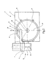
- the finishing device 1 is in plan view in Direction of arrow II shown in Figure 1. It is clearly recognizable how the finishing stone 17 on the Inner surface 18 abuts.
- the holder 16 has one Pressure device 19, via which the finishing stone 17 with constant force is pressed onto the inner surface 18.
- the pivoting device 7 in is moved over the slide 10 Direction of double arrow 20, i.e. Move in the X direction.
- the two slides 3 and 10 thus allow the descent the inner surface 18 of the workpiece 14 in the x-y plane 21.
- About the pivoting device 7 is also the Finished stone 17 pivoted about the pivot axis 9, so that it is permanently flat on the inner surface 18 is applied.
- the pivot axis 9 is at a distance from Inner surface 18.
- Swivel arm 8 there is also the possibility that the pivot axis 9 exactly in the interface between the inner surface 18 and the finishing stone 17 comes.
- any workpieces with flat or cylindrical ones Surfaces are processed. They usually have However, workpieces have surfaces that are cutouts Represent torus.
- Figure 3 there are several outer rings (top) and inner rings (bottom) of various roller bearings shown.
- Figure 3a shows an angle adjustable Floating bearing, the inner surface 18 of the finishing stone 17th is processed.
- This finishing stone 17 is in the X direction Move 20 (vertical) and 5 (horizontal) in the Y direction and the swivel device 7 and the swivel angle ⁇ pivoted. This also applies to the outer surface 18 'of the The inner ring.
- Figure 3b shows a spherical roller bearing in which the Outer ring compared to Figure 3a a smaller one Has radius of curvature.
- the inner ring has in this Case two inner surfaces 18 'to be machined.
- the figure 3c shows an axial spherical roller bearing with inclined curved surfaces 18 and 18 '.
- the Inner ring another surface to be machined 18 '', which is processed with a finishing stone 17 '.
- Figure 3d shows a tapered roller bearing with tapered Surfaces 18 and 18 ', in which case the finishing stone is only inclined, but is not pivoted. Also here the inner ring has a second one to be machined Surface 18 '', which is finished with a finishing stone 17 ' is processed.
- Figure 3e shows a cylindrical roller bearing cylindrical surfaces 18 and 18 ', here the Finishing stone 17 is neither inclined nor pivoted.
- Figure 3f shows a deep groove ball bearing in which the Surfaces 18 and 18 'have very small radii of curvature have so that the finishing stone 17 in the X direction 20 and Y direction 5 is almost not moved, but the Swivel angle ⁇ is relatively large.
- finishing device 1 can also Thrust bearings or thrust ball bearings are machined, whereby in the case of thrust bearings, the surface to be machined is flat.
Description
Die Erfindung betrifft eine Vorrichtung zum Superfinishen bearbeiteter, insbesondere gefinishter oder geschliffener Oberflächen von Werkstücken, mit einer Spanneinrichtung für das Werkstück, einem Finishstein als Werkzeug, einem Halter für den Finishstein, einer mehrachsigen Antriebsvorrichtung zum Ausführen einer mehrachsigen Relativbewegung zwischen der zu bearbeitenden Oberfläche und dem Halter in einer zur bearbeitenden Oberfläche orthogonalen Ebene, welche durch die Koordinaten X und Y definiert ist, sowie einer Steuereinheit zur Ansteuerung der Antriebsvorrichtung, wobei die Steuereinheit Eingabemittel für die Eingabe des Profils der zu bearbeitenden Oberfläche sowie elektronische Rechenmittel aufweist. Eine derartige Vorrichtung gemäß des Oberbegriffes des Anspruchs 1 ist z.B. aus der US-A-4 485 592 bekannt. Es ist bekannt, dass geschliffene Oberflächen von Werkstücken, insbesondere von Wälzlagern, in einem weiteren Arbeitsgang gefinisht werden, wodurch zum einen die Rauhigkeit der Oberfläche vermindert, zum anderen die Formund Maßgenauigkeit erhöht wird. In der Regel werden bei diesem Finishvorgang bis zu 6 µm, in Sonderfällen sogar 50 µm und mehr Material abgetragen. Ebene Oberflächen werden mit einem ebenen Finishstein bearbeitet, der in der Ebene der Oberfläche bewegt wird. Gekrümmte Oberflächen werden ebenfalls mit einem Finishstein bearbeitet, wobei die Arbeitsfläche des Finishsteins in diesem Fall nicht eben sondern der Krümmung der zu bearbeitenden Oberfläche angepasst ist. Während der Bearbeitung wird der Stein verschwenkt, so dass er permanent flächig am zu bearbeitenden Werkstück bzw. an dessen zu bearbeitenden Oberfläche anliegt. Hierfür ist der Finishstein in einer Schwenkvorrichtung eingespannt, deren Schwenkachse im Krümmungsmittelpunkt der zu bearbeitenden Oberfläche liegt. Es hat sich gezeigt, dass mit derartigen Vorrichtungen nur eine begrenzte Anzahl von Werkstücken bearbeitet werden kann. Werkstücke mit schwach gekrümmten Oberflächen, d.h. mit Oberflächen deren Krümmungsradius sehr groß ist, können mit derartigen Vorrichtungen nicht bearbeitet werden, da der Schwenkarm zum Verschwenken des Finishsteins in der Regel zu kurz ist. Dies trifft insbesondere für winkeleinstellbare Loslager und große Pendelrollenlager zu. Außerdem sind CNC-Bearbeitungsmaschinen bekannt, mit denen Bearbeitungswerkzeuge, z.B. Bohrer, Drehmeißel u.dgl. im Raum verfahren werden können. Derartige Werkzeuge besitzen jedoch punkt- oder linienförmige Schneiden, so dass die Winkelstellung des Werkzeugs gegenüber dem Werkstück zwar durch den Spanwinkel bestimmt ist, dass dieser Spanwinkel jedoch in relativ großen Bereichen variabel sein kann. Derartige Maschinen eignen sich nicht für Werkzeuge, bei denen das Werkstück nicht punkt- oder linienförmig sondern flächig, nämlich über einen Finishstein bearbeitet wird. Dieser Finishstein muss relativ zum Werkzeug nicht nur in der X-Y-Ebene sondern auch in seiner Winkellage exakt positioniert sein, so dass die Schneidfläche des Finishsteins perianent flächig auf der zu bearbeitenden Oberfläche des Werkstücks aufliegt.The invention relates to a device for superfinishing machined, especially finished or sanded Workpiece surfaces, with a clamping device for the workpiece, a finishing stone as a tool, a holder for the finishing stone, a multi-axis drive device to perform a multi-axis relative movement between the surface to be processed and the holder in one machining surface orthogonal plane, which by the coordinates X and Y is defined, and one Control unit for controlling the drive device, wherein the control unit input means for entering the Profiles of the surface to be processed as well as electronic Has computing means. Such a device according to the preamble of claim 1 is e.g. known from US-A-4,485,592. It is known that ground surfaces of Workpieces, especially of rolling bearings, in another Finished work step, which on the one hand Roughness of the surface is reduced, on the other hand the shape and Dimensional accuracy is increased. As a rule, at this finishing process down to 6 µm, in special cases even 50 µm and more material removed. Become flat surfaces processed with a flat finishing stone, the one in the plane the surface is moved. Become curved surfaces also finished with a finishing stone, the In this case, the working surface of the finishing stone is not even but the curvature of the surface to be machined is adjusted. During processing, the stone pivoted so that it is permanently flat on machined workpiece or on the workpiece to be machined Surface is applied. For this the finishing stone is in one Swiveled device clamped, the swivel axis in the The center of curvature of the surface to be machined lies. It has been shown that with such devices only a limited number of workpieces can be processed can. Workpieces with slightly curved surfaces, i.e. with surfaces whose radius of curvature is very large can not be processed with such devices because the swivel arm for swiveling the finishing stone in the Is usually too short. This is especially true for Angularly adjustable floating bearings and large spherical roller bearings. In addition, CNC processing machines are known with which Machining tools, e.g. Drills, turning tools and the like in the Space can be moved. Have such tools however point or line-shaped cutting edges, so that the Angular position of the tool relative to the workpiece it is determined by the rake angle that this rake angle however can be variable in relatively large areas. Such machines are not suitable for tools which the workpiece is not punctiform or linear flat, namely processed via a finishing stone. This finishing stone not only has to be in relation to the tool the X-Y plane but also exactly in its angular position be positioned so that the cutting surface of the Finishstones flat on the surface to be machined Surface of the workpiece rests.
Der Erfindung liegt daher die Aufgabe zugrunde, eine Vorrichtung bereitzustellen, mit welcher auch derartige Werkstücke relativ einfach bearbeitet werden können.The invention is therefore based on the object To provide device with which such Workpieces can be processed relatively easily.
Diese Aufgabe wird mit einer Finishvorrichtung der eingangs genannten Art erfindungsgemäß dadurch gelöst, dass der Halter mittels einer Schwenkeinrichtung um eine zur X-Y-Ebene orthogonale virtuelle Schwenkachse verschwenkbar gelagert ist und dass der zur Position des Finishsteins korrespondierende Schwenkwinkel des Halters über die Rechenmittel ermittelbar ist und die Schwenkeinrichtung von der Steuereinheit ansteuerbar ist.This task is accomplished with a finishing device at the beginning mentioned type solved according to the invention in that the Holder by means of a swiveling device around the X-Y plane orthogonal virtual swivel axis can be swiveled is stored and that to the position of the finishing stone corresponding swivel angle of the holder over the Computing means can be determined and the swivel device from the control unit can be controlled.
Mit der erfindungsgemäßen Vorrichtung wird der Finishstein über die Antriebsvorrichtung nicht nur in der X-Y-Ebene verfahren sondern auch derart verschwenkt, dass der Finishstein permanent flächig auf der zu bearbeitenden Oberfläche aufliegt. Der zu jeder Position des Finishsteins korrespondierende Schwenkwinkel wird über die Rechenmittel aus der Geometrie der zu bearbeitenden Oberlfäche bzw. aus dem Profil des Werkstücks errechnet. Hierfür bedarf es in der Regel zweier Punkte sowie des Krümmungsradiusses der Oberfläche. Aus diesen Angaben wird der virtuelle Schwenkwinkel errechnet, um welchen der Finishstein ausschließlich verschwenkt wird. Da dieser virtuelle Schwenkwinkel einen sehr großen Abstand zur zu bearbeitenden Oberfläche haben kann, wird der Finishstein über die Antriebsvorrichtung in X-Richtung sowie in Y-Richtung verfahren und zusätzlich um eine tatsächliche Schwenkachse verschwenkt. Diese Bewegung in der Ebene sowie Verschwenkung um die tatsächliche Schwenkachse entspricht einem Verschwenken um die virtuelle Schwenkachse. Die tatsächliche Schwenkachse liegt jedoch innerhalb der Finishvorrichtung, insbesondere innerhalb der Schwenkeinrichtung und wird von einem Schwenklager gebildet. Mit der erfindungsgemäßen Vorrichtung können nun auch Werkstücke bearbeitet werden, die sehr große Krümmungsradien besitzen bzw. die eine ebene, zu bearbeitende Oberfläche aufweisen (deren Krümmungsradius unendlich ist).With the device according to the invention, the finishing stone about the drive device not only in the X-Y plane process but also pivoted such that the Finish stone permanently on the surface to be processed Surface rests. The to every position of the finishing stone corresponding swivel angle is calculated using the computing means from the geometry of the surface to be machined or the profile of the workpiece. This requires in the rule of two points and the radius of curvature of the Surface. From this information the virtual Swivel angle calculated by which the finishing stone is only pivoted. Because this virtual Swivel angle a very large distance to finishing surface via the drive device in the X direction and in the Y direction procedure and in addition to an actual one Swivel axis swiveled. This movement in the plane as well Pivoting around the actual pivot axis corresponds a pivoting around the virtual pivot axis. The however, the actual pivot axis lies within the Finishing device, particularly within the Swivel device and is from a swivel bearing educated. With the device according to the invention can now workpieces can also be machined that are very large Radii of curvature have or a plane, too surface (the radius of curvature is infinite).
Gemäß einem bevorzugten Ausführungsbeispiel ist die Schwenkeinrichtung in die Antriebsvorrichtung integriert. Über die Antriebsvorrichtung wird also der Finishstein in X- und in Y-Richtung verfahren, was dadurch erfolgt, dass über die Antriebsvorrichtung die Schwenkeinrichtung verfahren wird, an welcher der Halter für den Finishstein vorgesehen ist. Außerdem wird über die Schwenkeinrichtung der Halter und somit der Finishstein verschwenkt.According to a preferred embodiment, the Swivel device integrated in the drive device. So the finishing stone is in via the drive device Move X and Y direction, which is done by the swivel device via the drive device is moved on which the holder for the finishing stone is provided. In addition, the swivel device the holder and thus the finishing stone swiveled.
Es besteht jedoch auch die Möglichkeit, dass die Schwenkeinrichtung maschinenfest ist, und in der Schwenkeinrichtung eine Antriebsvorrichtung vorgesehen ist, welche den Halter für den Finishstein in zwei zueinander orthogonalen Richtungen verfährt.However, there is also a possibility that the Swivel device is machine-proof, and in the A drive device is provided, which the holder for the finishing stone in two to each other orthogonal directions.
Diese Schwenkeinrichtung kann erfindungsgemäß elektrisch, z.B. über Servomotoren o.dgl., elektromagnetisch, hydraulisch und/oder pneumatisch aktivierbar sein. According to the invention, this swiveling device can be electrically e.g. via servo motors or the like, electromagnetic, can be activated hydraulically and / or pneumatically.
Die erfindungsgemäße Vorrichtung ist dazu geeignet, ebene und gekrümmte Oberflächen, insbesondere Kreisbogenförmig oder torusförming gekrümmte Oberflächen, sowie konkave und konvexe Oberflächen zu bearbeiten. Außerdem können Oberflächen bearbeitet werden, die geneigt sind, so dass die virtuelle Schwenkachse außerhalb der Ebene des in der Regel ringförmigen Bauteils ist.The device according to the invention is suitable for level and curved surfaces, in particular arcuate or toroidal curved Surfaces, as well as concave and convex Machining surfaces. In addition, surfaces be edited that are inclined so that the virtual Pan axis outside the plane of the rule annular component.
Eine Weiterbildung sieht vor, dass der Halter und/oder die Antriebsvorrichtung eine Andruckeinrichtung für den Finishstein aufweist. Diese Andruckeinrichtung hält den Finishstein permanent auf der zu bearbeitenden Oberfläche und treibt diesen mit einer vorgegebenen Kraft an. Auf diese Weise wird der gewünschte Abtrag erzielt und der Verschleiss des Finishsteins ausgeglichen. Bevorzugt ist die Andruckeinrichtung pneumatisch oder hydraulisch beaufschlagbar, wobei der Finishstein auch mit Federkraft auf die zu bearbeitende Oberfläche gepresst werden kann. Eine pneumatische Vorrichtung hat den wesentlichen Vorteil, dass der Anpressdruck relativ einfach konstant gehalten werden kann.A further training provides that the holder and / or the Drive device a pressure device for the Has finishing stone. This pressure device holds the Finish stone permanently on the surface to be processed and drives it with a given force. On in this way the desired removal is achieved and the Compensation for wear of the finishing stone. Is preferred the pressure device is pneumatic or hydraulic loadable, the finishing stone also with spring force can be pressed onto the surface to be processed. A pneumatic device has the main advantage that the contact pressure is kept relatively constant relatively easily can be.
Die erfindungsgemäße Vorrichtung ist bei einer Variante so ausgeführt, dass die tatsächliche Schwenkachse in der Berührungsebene von Finishstein und zu bearbeitender Oberfläche liegt. Bei einem bevorzugten Ausführungsbeispiel liegt die tatsächliche Schwenkachse zwischen der Berührungsebene und dem Ort der virtuellen Schwenkachse. Bevorzugt ist die Lage der tatsächlichen Schwenkachse bezüglich der zu bearbeitenden Oberfläche verstellbar.The device according to the invention is so in a variant executed that the actual pivot axis in the Contact level of the finishing stone and the one to be machined Surface lies. In a preferred embodiment the actual swivel axis lies between the Touch level and the location of the virtual swivel axis. The position of the actual pivot axis is preferred adjustable with regard to the surface to be processed.
Weitere Vorteile, Merkmale und Einzelheiten der Erfindung ergeben sich aus den Unteransprüchen sowie der nachfolgenden Beschreibung in der unter Bezugnahme auf die Zeichnung ein besonders bevorzugtes Ausführungsbeispiel im einzelnen beschrieben ist. In der Zeichnung zeigen:
- Figur 1
- eine Seitenansicht der erfindungsgemäßen Finishvorrichtung;
Figur 2- eine Draufsicht in Richtung des Pfeils II gemäß Figur 1; und
Figur 3- mehrere Werkstücke, welche mit der Vorrichtung bearbeitet werden können.
- Figure 1
- a side view of the finishing device according to the invention;
- Figure 2
- a plan view in the direction of arrow II of Figure 1; and
- Figure 3
- several workpieces that can be processed with the device.
Die Figur 1 zeigt eine insgesamt mit 1 bezeichnete
Finishvorrichtung mit einem Maschinengehäuse 2, in welchem
Versorgungsaggregate, Antriebe, eine Steuereinheit 23 mit
Rechenmitteln u.dgl. für die Vorrichtung 1 untergebracht
sind. Am Maschinengehäuse 2 befindet sich ein Schlitten 3
der an einer vertikalen Führungsbahn 4 in Y-Richtung
(Doppelpfeil 5) verfahrbar ist. An diesem Schlitten 3 ist
über einen Tragarm 6 eine Schwenkeinrichtung 7 befestigt,
an welcher ein Schwenkarm 8 um eine Schwenkachse 9
verschwenkbar gelagert ist. Diese Schwenkeinrichtung 7 ist
über den Schlitten 3 in vertikaler Richtung verfahrbar.
Zwischen der Schwenkeinrichtung 7 und dem Tragarm 6
befindet sich ein weiterer Schlitten 10, über welchen die
Schwenkeinrichtung 7 in einer zur Zeichenebene orthogonalen
Richtung, nämlich in Richtung der x-Achse, verfahrbar ist.FIG. 1 shows an overall designated 1
Finishing device with a
Innerhalb des Maschinengehäuses 2 befindet sich ein
Drehantrieb mit einer Drehachse 11, über welchen eine
Planscheibe 12 in Drehung versetzt werden kann. An dieser
Planscheibe 12 ist über Haltevorrichtungen 13 ein Werkstück
14 befestigt, welches um die Drehachse 11 gedreht werden
kann. Dabei liegen die Drehachse 11 und die zentrale Achse
des Werkstücks 14 koaxial zueinander. Der Schwenkarm 8
besitzt die Form eines nach unten offenen U und greift mit
seinem freien Ende in das Werkstück 14 ein. An diesem
freien Ende 15 befindet sich ein Halter 16, welcher einen
Finishstein 17 aufnimmt. Dieser Finishstein 17 greift an
der zu bearbeitenden Innenoberfläche 18 (Figur 2) an. An
dieser Innenoberfläche 18 liegt der Finishstein 17 flächig
an. Er besitzt also an seiner Anlagefläche die gleiche
Krümmung wie die Innenoberfläche 18.There is a inside the
Die beiden Schlitten 3 und 10 bilden eine
Antriebsvorrichtung 22 für den Halter 16 bzw. den
Finishstein 17 in X-Richtung 20 sowie in Y-Richtung 5.The two
In der Figur 2 ist die Finishvorrichtung 1 in Draufsicht in
Richtung des Pfeils II gemäß Figur 1 dargestellt. Es ist
deutlich erkennbar, wie der Finishstein 17 an der
Innenoberfläche 18 anliegt. Der Halter 16 besitzt eine
Andruckeinrichtung 19, über welche der Finishstein 17 mit
konstanter Kraft auf die Innenoberfläche 18 gepresst wird.
Über den Schlitten 10 wird die Verschwenkeinrichtung 7 in
Richtung des Doppelpfeils 20, d.h. in X-Richtung verfahren.
Die beiden Schlitten 3 und 10 erlauben also das Abfahren
der Innenoberfläche 18 des Werkstücks 14 in der x-y-Ebene
21. Über die Schwenkeinrichtung 7 wird außerdem der
Finishstein 17 um die Schwenkachse 9 derart verschwenkt, so
dass dieser permanent flächig an der Innenoberfläche 18
anliegt. Dabei liegt die Schwenkachse 9 mit Abstand zur
Innenoberfläche 18. Bei Verwendung eines anders geformten
Schwenkarmes 8 besteht jedoch auch die Möglichkeit, dass
die Schwenkachse 9 exakt in der Berührungsfläche zwischen
der Innenoberfläche 18 und dem Finishstein 17 zu liegen
kommt. In Figure 2, the finishing device 1 is in plan view in
Direction of arrow II shown in Figure 1. It is
clearly recognizable how the finishing
Mit der erfindungsgemäßen Finishvorrichtung 1 können
beliebige Werkstücke mit ebenen oder zylinderförmigen
Oberflächen bearbeitet werden. Üblicherweise besitzen die
Werkstücke jedoch Oberflächen, welche Ausschnitte eines
Torus darstellen. In der Figur 3 sind mehrere Außenringe
(oben) sowie Innenringe (unten) verschiedener Wälzlager
dargestellt. Die Figur 3a zeigt ein winkeleinstellbares
Loslager, dessen Innenoberfläche 18 vom Finishstein 17
bearbeitet wird. Dieser Finishstein 17 wird in X-Richtung
20 (vertikal) und in Y-Richtung 5 (horizontal) verfahren
und von der Schwenkeinrichtung 7 und dem Schwenkwinkel α
verschwenkt. Dies gilt auch für die Außenoberfläche 18' des
Innenrings.With the finishing device 1 according to the invention
any workpieces with flat or cylindrical ones
Surfaces are processed. They usually have
However, workpieces have surfaces that are cutouts
Represent torus. In Figure 3 there are several outer rings
(top) and inner rings (bottom) of various roller bearings
shown. Figure 3a shows an angle adjustable
Floating bearing, the
Die Figur 3b zeigt ein Pendelrollenlager, bei der der
Außenring gegenüber zur Figur 3a einen kleineren
Krümmungsradius aufweist. Der Innenring besitzt in diesem
Fall zwei zu bearbeitende Innenoberflächen 18'. Die Figur
3c zeigt ein Axialpendelrollenlager mit geneigten,
gekrümmten Oberflächen 18 und 18'. Außerdem weist der
Innenring eine weitere zu bearbeitende Oberfläche 18'' auf,
welche mit einem Finishstein 17' bearbeitet wird.Figure 3b shows a spherical roller bearing in which the
Outer ring compared to Figure 3a a smaller one
Has radius of curvature. The inner ring has in this
Case two inner surfaces 18 'to be machined. The figure
3c shows an axial spherical roller bearing with inclined
Die Figur 3d zeigt ein Kegelrollenlager mit kegelförmigen
Flächen 18 und 18', wobei in diesem Falle der Finishstein
lediglich geneigt ist, jedoch nicht verschwenkt wird. Auch
hier weist der Innenring eine zweite zu bearbeitende
Oberfläche 18'' auf, welche mit einem Finishstein 17'
bearbeitet wird.Figure 3d shows a tapered roller bearing with tapered
Die Figur 3e zeigt ein Zylinderrollenlager mit
zylindrischen Oberflächen 18 und 18', wobei hier der
Finishstein 17 weder geneigt ist noch verschwenkt wird.Figure 3e shows a cylindrical roller bearing
Die Figur 3f zeigt ein Rillenkugellager, bei dem die
Oberflächen 18 und 18' sehr kleine Krümmungsradien
besitzen, so dass der Finishstein 17 in X-Richtung 20 und
Y-Richtung 5 nahezu nicht verfahren wird, jedoch der
Schwenkwinkel α relativ groß ist.Figure 3f shows a deep groove ball bearing in which the
Mit der erfindungsgemäßen Finishvorrichtung 1 können auch Axiallager oder Axialkugellager bearbeitet werden, wobei bei Axiallagern die zu bearbeitende Fläche eben ist. Insgesamt kann festgestellt werden, dass, wie in Figur 3 dargestellt, ebene Flächen sowie Ausschnittsflächen eines Torus bearbeitet werden können.With the finishing device 1 according to the invention can also Thrust bearings or thrust ball bearings are machined, whereby in the case of thrust bearings, the surface to be machined is flat. Overall, it can be stated that, as in FIG shown, flat surfaces and cut-out surfaces of a Torus can be edited.
Claims (6)
- A device for superfinishing of treated, in particular finished or ground, surfaces (18) of work pieces (14), having a clamping device (13) for the workpiece (14), a finishing block (17) as the tool, a holder (16) for the finishing block (17), a multi-axis drive device (22) for performing a multi-axis relative movement between the surface (18) to be treated and the holder (16) in a plane (21) which is orthogonal in respect to the surface (18) to be treated and is defined by the coordinates X and Y (20 and 5), as well as a control unit for controlling the drive device (22), wherein the control unit (23) has input means for inputting the profile of the surface (18) to be treated, and the control unit (23) has electronic calculating means, characterized in that by means of a pivoting device (7) the holder (16) is seated pivotable around a virtual pivot axis which is orthogonal in respect to the X - Y - plane (21), and that the pivot angle (α) of the holder (16) corresponding to the position of the finishing block (17) can be determined by means of the calculating means, and that the pivoting device (7) can be controlled from the control unit (23).
- The device in accordance with claim 1, characterized in that the pivoting device (7) is integrated into the drive device (22).
- The device in accordance with one of the preceding claims, characterized in that the pivoting device (7) can be electrically, electro-magnetically, hydraulically and/or pneumatically activated.
- The device in accordance with one of the preceding claims, characterized in that the holder (16) and/or the drive device (22) has a contact pressure device (19) for the finishing block (17).
- The device in accordance with claim 4, characterized in that the contact pressure device (19) can be charged pneumatically or hydraulically, or that it presses the finishing block (17) at the surface (18) to be worked by means of a spring force.
- The device in accordance with one of the preceding claims, characterized in that the actual pivot axis (9) is located in the tangent plane between the finishing block (17) and the surface (18) to be treated, or lies between the tangent plane and the location of the virtual pivot axis.
Applications Claiming Priority (2)
| Application Number | Priority Date | Filing Date | Title |
|---|---|---|---|
| DE19804885 | 1998-02-09 | ||
| DE19804885A DE19804885C5 (en) | 1998-02-09 | 1998-02-09 | Superfinishing device |
Publications (3)
| Publication Number | Publication Date |
|---|---|
| EP0936028A2 EP0936028A2 (en) | 1999-08-18 |
| EP0936028A3 EP0936028A3 (en) | 2002-04-17 |
| EP0936028B1 true EP0936028B1 (en) | 2003-10-29 |
Family
ID=7856935
Family Applications (1)
| Application Number | Title | Priority Date | Filing Date |
|---|---|---|---|
| EP98111690A Expired - Lifetime EP0936028B1 (en) | 1998-02-09 | 1998-06-25 | Apparatus for superfinishing machined surfaces |
Country Status (3)
| Country | Link |
|---|---|
| US (1) | US6203401B1 (en) |
| EP (1) | EP0936028B1 (en) |
| DE (2) | DE19804885C5 (en) |
Cited By (5)
| Publication number | Priority date | Publication date | Assignee | Title |
|---|---|---|---|---|
| EP2095906A1 (en) | 2008-02-26 | 2009-09-02 | Thielenhaus Technologies GmbH | Device for mechanically finishing baring surfaces of bearings |
| DE102008046451A1 (en) | 2008-09-09 | 2010-03-11 | Thielenhaus Technologies Gmbh | Device for universal mechanical finishing treatment of cylindrical and spherical surfaces at roller bearing ring for e.g. roller bearing, has carriage guide attached to shaft that is supported in housing and is attached to drive |
| DE102009040062A1 (en) | 2009-09-07 | 2011-03-10 | Thielenhaus Technologies Gmbh | Device for finishing bearing ring, has tool turret whose tool holder is loaded with short-stroke device and receives machining tools, where short-stroke device includes oscillating drive to generate oscillation movement of stone holder |
| DE102009059991B3 (en) * | 2009-12-22 | 2011-06-01 | Thielenhaus Technologies Gmbh | Device for superfinish machining of workpieces, particularly annular workpieces, has cross slide and superfinishing unit, where unit is attached at cross slide |
| DE102010036470A1 (en) | 2010-07-16 | 2012-01-19 | Thielenhaus Technologies Gmbh | Device for honing e.g. conical running surfaces, of roller bearing ring of large bearing, has eccentric cam drive for creation of oscillating movements of tool base support, where tool base support includes adjustable tool connector |
Families Citing this family (11)
| Publication number | Priority date | Publication date | Assignee | Title |
|---|---|---|---|---|
| US6382815B1 (en) | 2000-05-16 | 2002-05-07 | Jjk Industries, L.P. | Energized body jewelry |
| US7785173B2 (en) * | 2005-07-05 | 2010-08-31 | Supfina Machine Co. | Superfinishing machine and method |
| EP1884315B1 (en) | 2006-08-03 | 2010-11-17 | Supfina Grieshaber GmbH & Co. KG | Tool, apparatus and method for the manufacturung of a workpiece, especially of a worm gear |
| DE102011007731A1 (en) * | 2011-04-20 | 2012-10-25 | Supfina Grieshaber Gmbh & Co. Kg | Finishing device for finish machining of work piece, has finishing stone holder for holding finishing stone and work piece drive for driving work piece around rotational axis |
| CN102950521A (en) * | 2011-08-31 | 2013-03-06 | 上海通用轴承有限公司 | Equipment and method for machining bearing raceway |
| EP2596907A1 (en) * | 2011-11-28 | 2013-05-29 | Supfina Grieshaber GmbH & Co. KG | Device for finishing a surface of a bent workpiece |
| DE102011087252B3 (en) * | 2011-11-28 | 2013-01-17 | Supfina Grieshaber Gmbh & Co. Kg | Device for finish machining of ring-shaped workpiece, has support for connection with finishing tool holder, drive unit, oscillation unit and auxiliary drive unit where oscillation unit is connected with support by connecting unit |
| JP5968181B2 (en) * | 2012-09-28 | 2016-08-10 | セイコーインスツル株式会社 | Rolling bearing polishing equipment |
| EP2871024B1 (en) | 2013-11-12 | 2016-02-03 | Supfina Grieshaber GmbH & Co. KG | Device for finishing a curved surface of a workpiece and method for operating the device |
| DE102014102282B4 (en) * | 2014-02-21 | 2019-11-14 | Thielenhaus Technologies Gmbh | Finish tool carrier and finishing unit |
| JP6517105B2 (en) * | 2015-07-21 | 2019-05-22 | Ntn株式会社 | Superfinishing method of roller bearing rolling surface |
Family Cites Families (9)
| Publication number | Priority date | Publication date | Assignee | Title |
|---|---|---|---|---|
| JPS58109266A (en) * | 1981-12-23 | 1983-06-29 | Osaka Seiki Kk | Super finishing for ring-shaped work |
| DE3225977A1 (en) * | 1982-07-10 | 1984-01-12 | Supfina Maschinenfabrik Hentzen GmbH & Co KG, 5630 Remscheid | METHOD AND DEVICE FOR FINELY FINISHING CONVEX OR CONCAVE COVERING SURFACES OF ROTATION-SYMMETRICAL WORKPIECES, IN PARTICULAR OF ROLLER BEARING REELS |
| JPS59115157A (en) * | 1982-12-22 | 1984-07-03 | Osaka Seiki Kk | Superfinishing device of annular workpiece |
| US5934975A (en) * | 1987-09-04 | 1999-08-10 | Svanberg; Gunnar K. | Dental curet and sharpening machine system |
| FR2639272B1 (en) * | 1988-11-18 | 1991-02-15 | Glaenzer Spicer Sa | METHODS AND APPARATUS FOR PRECISE POSITIONING OF A ROLLER SEGMENT FOR THE FINISHING OF ITS TURNING CAPACITY, AND METHOD FOR MACHINING THE EDGES OF SUCH A DEVICE |
| US5097635A (en) * | 1990-08-06 | 1992-03-24 | Keystone Valvtron, Inc. | Method and apparatus for automatic ball to seat lapping |
| DE4423422A1 (en) * | 1994-07-06 | 1996-01-11 | Grieshaber Masch | Process for fine external machining, in particular rotationally symmetrical bodies |
| US5681209A (en) * | 1996-01-29 | 1997-10-28 | Constant Velocity Systems, Inc. | Housing grinding machine |
| US5816899A (en) * | 1996-07-22 | 1998-10-06 | Buehler, Ltd. | Micro precise polishing apparatus |
-
1998
- 1998-02-09 DE DE19804885A patent/DE19804885C5/en not_active Expired - Fee Related
- 1998-06-25 EP EP98111690A patent/EP0936028B1/en not_active Expired - Lifetime
- 1998-06-25 DE DE59810022T patent/DE59810022D1/en not_active Expired - Lifetime
- 1998-08-31 US US09/139,128 patent/US6203401B1/en not_active Expired - Lifetime
Cited By (8)
| Publication number | Priority date | Publication date | Assignee | Title |
|---|---|---|---|---|
| EP2095906A1 (en) | 2008-02-26 | 2009-09-02 | Thielenhaus Technologies GmbH | Device for mechanically finishing baring surfaces of bearings |
| DE102008011215A1 (en) | 2008-02-26 | 2009-09-03 | Thielenhaus Technologies Gmbh | Device for the mechanical finishing of running surfaces on roller bearing rings |
| DE102008046451A1 (en) | 2008-09-09 | 2010-03-11 | Thielenhaus Technologies Gmbh | Device for universal mechanical finishing treatment of cylindrical and spherical surfaces at roller bearing ring for e.g. roller bearing, has carriage guide attached to shaft that is supported in housing and is attached to drive |
| DE102008046451B4 (en) * | 2008-09-09 | 2011-06-09 | Thielenhaus Technologies Gmbh | Device for mechanical finishing of peripheral surfaces of rotationally symmetrical workpieces, in particular rolling bearing rings |
| DE102009040062A1 (en) | 2009-09-07 | 2011-03-10 | Thielenhaus Technologies Gmbh | Device for finishing bearing ring, has tool turret whose tool holder is loaded with short-stroke device and receives machining tools, where short-stroke device includes oscillating drive to generate oscillation movement of stone holder |
| DE102009059991B3 (en) * | 2009-12-22 | 2011-06-01 | Thielenhaus Technologies Gmbh | Device for superfinish machining of workpieces, particularly annular workpieces, has cross slide and superfinishing unit, where unit is attached at cross slide |
| DE102010036470A1 (en) | 2010-07-16 | 2012-01-19 | Thielenhaus Technologies Gmbh | Device for honing e.g. conical running surfaces, of roller bearing ring of large bearing, has eccentric cam drive for creation of oscillating movements of tool base support, where tool base support includes adjustable tool connector |
| DE102010036470B4 (en) | 2010-07-16 | 2018-04-26 | Thielenhaus Technologies Gmbh | Device for honing running surfaces on roller bearing rings |
Also Published As
| Publication number | Publication date |
|---|---|
| EP0936028A2 (en) | 1999-08-18 |
| DE19804885A1 (en) | 1999-08-19 |
| DE19804885C2 (en) | 1999-12-09 |
| DE59810022D1 (en) | 2003-12-04 |
| US6203401B1 (en) | 2001-03-20 |
| EP0936028A3 (en) | 2002-04-17 |
| DE19804885C5 (en) | 2004-07-15 |
Similar Documents
| Publication | Publication Date | Title |
|---|---|---|
| EP0936028B1 (en) | Apparatus for superfinishing machined surfaces | |
| DE3519402C2 (en) | ||
| DE102005021640B4 (en) | Machine for processing optical workpieces, in particular plastic spectacle lenses | |
| EP0799109B1 (en) | Hardened workpiece finishing process | |
| DE60203154T2 (en) | Device for processing spectacle lenses | |
| EP2394783B1 (en) | Rotary grinding machine without points and method for grinding without points with height-adjustable control wheel | |
| WO2010142670A1 (en) | Grinding-supporting device | |
| DE19616526A1 (en) | Machine for the machining of optical materials for the production of optical parts | |
| EP2080590A1 (en) | Device and method to trim a processing disk using a rotating processing tool and tool device with such a device | |
| DE2718339C3 (en) | Grinding wheel dressing device | |
| DE102007021659B4 (en) | Surface grinding process and surface grinding machine | |
| CH684250A5 (en) | A method for numerically controlled machining of a workpiece on a grinding machine. | |
| CH694940A5 (en) | Centreless grinding machine. | |
| DE2007973A1 (en) | Device for dressing a grinding wheel for gear cutting machines | |
| CH671912A5 (en) | ||
| DE2659489A1 (en) | Milling machine for aspherical faces of optical lenses - has workpiece carrier on cross table with X and Y slides movable independently | |
| DE2807268A1 (en) | Centre and edge grinder for optical lenses - uses two part spindle to hold lens at top and bottom during machining under NC | |
| DE2423567C2 (en) | Device for milling or grinding the contours of stones or other materials | |
| DE3933863A1 (en) | NC slideway-type precision grinding machine - has grinding head with additional axes of movement to facilitate NC grinding of curved ways | |
| DE102014014877A1 (en) | A centerless cylindrical grinding apparatus and method of using a centerless cylindrical grinding apparatus | |
| DE19616525A1 (en) | Tool for material removing machining of optical materials | |
| DE4433715C1 (en) | Machine for surface treating edges of gravestone | |
| EP4100205A1 (en) | Method and device for cylindrical grinding | |
| CH685684A5 (en) | Grinder. | |
| DD269345A1 (en) | METHOD FOR RANGING PROFILED GRINDING BODIES |
Legal Events
| Date | Code | Title | Description |
|---|---|---|---|
| PUAI | Public reference made under article 153(3) epc to a published international application that has entered the european phase |
Free format text: ORIGINAL CODE: 0009012 |
|
| AK | Designated contracting states |
Kind code of ref document: A2 Designated state(s): AT BE CH CY DE DK ES FI FR GB GR IE IT LI LU MC NL PT SE Kind code of ref document: A2 Designated state(s): DE FR GB SE |
|
| AX | Request for extension of the european patent |
Free format text: AL;LT;LV;MK;RO;SI |
|
| RAP1 | Party data changed (applicant data changed or rights of an application transferred) |
Owner name: SUPFINA GRIESHABER GMBH & CO. KG |
|
| PUAL | Search report despatched |
Free format text: ORIGINAL CODE: 0009013 |
|
| AK | Designated contracting states |
Kind code of ref document: A3 Designated state(s): AT BE CH CY DE DK ES FI FR GB GR IE IT LI LU MC NL PT SE |
|
| AX | Request for extension of the european patent |
Free format text: AL;LT;LV;MK;RO;SI |
|
| 17P | Request for examination filed |
Effective date: 20021016 |
|
| AKX | Designation fees paid |
Free format text: DE FR GB SE |
|
| GRAH | Despatch of communication of intention to grant a patent |
Free format text: ORIGINAL CODE: EPIDOS IGRA |
|
| GRAH | Despatch of communication of intention to grant a patent |
Free format text: ORIGINAL CODE: EPIDOS IGRA |
|
| GRAA | (expected) grant |
Free format text: ORIGINAL CODE: 0009210 |
|
| AK | Designated contracting states |
Kind code of ref document: B1 Designated state(s): DE FR GB SE |
|
| REG | Reference to a national code |
Ref country code: GB Ref legal event code: FG4D Free format text: NOT ENGLISH |
|
| GBT | Gb: translation of ep patent filed (gb section 77(6)(a)/1977) |
Effective date: 20031029 |
|
| REG | Reference to a national code |
Ref country code: IE Ref legal event code: FG4D Free format text: GERMAN |
|
| REF | Corresponds to: |
Ref document number: 59810022 Country of ref document: DE Date of ref document: 20031204 Kind code of ref document: P |
|
| REG | Reference to a national code |
Ref country code: SE Ref legal event code: TRGR |
|
| REG | Reference to a national code |
Ref country code: IE Ref legal event code: FD4D |
|
| ET | Fr: translation filed | ||
| PLBE | No opposition filed within time limit |
Free format text: ORIGINAL CODE: 0009261 |
|
| STAA | Information on the status of an ep patent application or granted ep patent |
Free format text: STATUS: NO OPPOSITION FILED WITHIN TIME LIMIT |
|
| 26N | No opposition filed |
Effective date: 20040730 |
|
| PGFP | Annual fee paid to national office [announced via postgrant information from national office to epo] |
Ref country code: FR Payment date: 20100706 Year of fee payment: 13 |
|
| PGFP | Annual fee paid to national office [announced via postgrant information from national office to epo] |
Ref country code: GB Payment date: 20100525 Year of fee payment: 13 |
|
| GBPC | Gb: european patent ceased through non-payment of renewal fee |
Effective date: 20110625 |
|
| REG | Reference to a national code |
Ref country code: FR Ref legal event code: ST Effective date: 20120229 |
|
| PG25 | Lapsed in a contracting state [announced via postgrant information from national office to epo] |
Ref country code: FR Free format text: LAPSE BECAUSE OF NON-PAYMENT OF DUE FEES Effective date: 20110630 |
|
| PG25 | Lapsed in a contracting state [announced via postgrant information from national office to epo] |
Ref country code: GB Free format text: LAPSE BECAUSE OF NON-PAYMENT OF DUE FEES Effective date: 20110625 |
|
| PGFP | Annual fee paid to national office [announced via postgrant information from national office to epo] |
Ref country code: SE Payment date: 20140623 Year of fee payment: 17 |
|
| REG | Reference to a national code |
Ref country code: SE Ref legal event code: EUG |
|
| PG25 | Lapsed in a contracting state [announced via postgrant information from national office to epo] |
Ref country code: SE Free format text: LAPSE BECAUSE OF NON-PAYMENT OF DUE FEES Effective date: 20150626 |
|
| PGFP | Annual fee paid to national office [announced via postgrant information from national office to epo] |
Ref country code: DE Payment date: 20160622 Year of fee payment: 19 |
|
| REG | Reference to a national code |
Ref country code: DE Ref legal event code: R119 Ref document number: 59810022 Country of ref document: DE |
|
| PG25 | Lapsed in a contracting state [announced via postgrant information from national office to epo] |
Ref country code: DE Free format text: LAPSE BECAUSE OF NON-PAYMENT OF DUE FEES Effective date: 20180103 |