EP0936017A2 - Dichtungsanordnung des unteren Führungskopfes in einer Drahtschneidefunkenerosionsmaschine - Google Patents
Dichtungsanordnung des unteren Führungskopfes in einer Drahtschneidefunkenerosionsmaschine Download PDFInfo
- Publication number
- EP0936017A2 EP0936017A2 EP99500021A EP99500021A EP0936017A2 EP 0936017 A2 EP0936017 A2 EP 0936017A2 EP 99500021 A EP99500021 A EP 99500021A EP 99500021 A EP99500021 A EP 99500021A EP 0936017 A2 EP0936017 A2 EP 0936017A2
- Authority
- EP
- European Patent Office
- Prior art keywords
- window
- metal strip
- tank
- sealing
- frame
- Prior art date
- Legal status (The legal status is an assumption and is not a legal conclusion. Google has not performed a legal analysis and makes no representation as to the accuracy of the status listed.)
- Withdrawn
Links
Images
Classifications
-
- B—PERFORMING OPERATIONS; TRANSPORTING
- B23—MACHINE TOOLS; METAL-WORKING NOT OTHERWISE PROVIDED FOR
- B23H—WORKING OF METAL BY THE ACTION OF A HIGH CONCENTRATION OF ELECTRIC CURRENT ON A WORKPIECE USING AN ELECTRODE WHICH TAKES THE PLACE OF A TOOL; SUCH WORKING COMBINED WITH OTHER FORMS OF WORKING OF METAL
- B23H7/00—Processes or apparatus applicable to both electrical discharge machining and electrochemical machining
- B23H7/02—Wire-cutting
Definitions
- the working tank which contains a working liquid for EDM is provided on one of its side walls with a window by which can penetrate the lower arm of the machine.
- the solution proposed in this invention starts from the idea of not modify in any way the structure of any of the tanks currently known and to incorporate an external addition to it which provides a solution to the problem of tightness and movement of the arm without bringing any effort on it latest.
- the addition or device object of this invention is assembled externally, for example by screws, to a tank currently in service, this operation being simple and inexpensive.
- the invention also considers that if the seals are completely waterproof, it is transmitted, in the movement, efforts not desirable on the lower arm, hence it designs a semi-tight seal between metal blade and lower arm, providing the assembly with a conduit overflow which collects the liquid which escapes through the seals or semi-tightness.
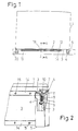
- Figure 1 is a sectional plan view of an embodiment practice of the subject of the invention.
- Figure 2 is a perspective from a lateral side of Figure 1 with a window to be able to observe the spring mechanism.
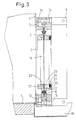
- FIG. 3 is a view along section A: A of FIG. 1.
- reservoir (1) container of fluid for work EDM with the window (2) made in one of its side walls which allows the passage and movement of the carrying arm of the lower headstock of the EDM machine, all in a manner already known.
- the winding device (4) comprises an axis (e) on which attaches the end of a torsion spring (8) which fixes its other end to a winding cylinder (9) to which the lateral edge of the strip (3) is assembled.
- the head (10) of the axis (e) of the winding device (4) is accessible from the outside so as to give it a pre-charge determined to the torsion spring (8) or that it can be varied at will, by having the corresponding calibration screw (11) in order to maintain said axis in the desired position.
- a structural frame which constitutes an internal frame (12) connected to the tank (1) by means of screws (13) and in an external frame (14), which is assembled to the inner frame (12) by means of screws (15).
- a sealing frame consisting of two semi-frames (16) which are end in rubber lip-beads (17) which rest on the strip (3) giving rise to a seal which it is not necessary that it is a total seal, and this, so that the flange (3) can slide easily between said beads (17) which promotes movement without excessive and damaging tension on the lower arm of the machine which penetrates through an orifice (18) in the strip (3).
- the seal between the band (3) and the lower arm of the machine is obtained by a semi-tight seal which allows the partial exit of liquid towards a collection conduit (19) with its overflow chute (20) for its recycling.
- Said semi-tightness allows a slight sliding of the arm lower in the hole (18) avoiding unnecessary and harmful efforts on said arm.
- the semi-watertight seal is composed by the interior side of the metal strip (3) of a metal flange (21) having a recess annular to contain a ring (22) of cellular polyurethane and is consists of the outer side of a counter flange (23) having a recess frontal annular which contains a ring (24) of spongy material retained by a cover (25).
Landscapes
- Chemical & Material Sciences (AREA)
- Chemical Kinetics & Catalysis (AREA)
- Electrochemistry (AREA)
- Engineering & Computer Science (AREA)
- Mechanical Engineering (AREA)
- Electrical Discharge Machining, Electrochemical Machining, And Combined Machining (AREA)
Applications Claiming Priority (2)
| Application Number | Priority Date | Filing Date | Title |
|---|---|---|---|
| ES9800265A ES2155319B1 (es) | 1998-02-11 | 1998-02-11 | Dispositivo de estanqueidad para brazo inferior de una maquina de electroerosion. |
| ES9800265 | 1998-02-11 |
Publications (2)
| Publication Number | Publication Date |
|---|---|
| EP0936017A2 true EP0936017A2 (de) | 1999-08-18 |
| EP0936017A3 EP0936017A3 (de) | 2004-01-14 |
Family
ID=8302704
Family Applications (1)
| Application Number | Title | Priority Date | Filing Date |
|---|---|---|---|
| EP99500021A Withdrawn EP0936017A3 (de) | 1998-02-11 | 1999-02-09 | Dichtungsanordnung des unteren Führungskopfes in einer Drahtschneidefunkenerosionsmaschine |
Country Status (2)
| Country | Link |
|---|---|
| EP (1) | EP0936017A3 (de) |
| ES (1) | ES2155319B1 (de) |
Family Cites Families (3)
| Publication number | Priority date | Publication date | Assignee | Title |
|---|---|---|---|---|
| CH654777A5 (fr) * | 1983-07-27 | 1986-03-14 | Charmilles Sa Ateliers | Machine pour decouper par electro-erosion. |
| JPS60186319A (ja) * | 1984-02-29 | 1985-09-21 | Brother Ind Ltd | ワイヤ−カツト放電加工機 |
| EP0610974B1 (de) * | 1990-10-26 | 1998-03-18 | Sodick Co., Ltd. | Funkenerosive Drahtschneideinrichtung |
-
1998
- 1998-02-11 ES ES9800265A patent/ES2155319B1/es not_active Expired - Fee Related
-
1999
- 1999-02-09 EP EP99500021A patent/EP0936017A3/de not_active Withdrawn
Also Published As
| Publication number | Publication date |
|---|---|
| EP0936017A3 (de) | 2004-01-14 |
| ES2155319B1 (es) | 2002-01-16 |
| ES2155319A1 (es) | 2001-05-01 |
Similar Documents
| Publication | Publication Date | Title |
|---|---|---|
| EP0304882B1 (de) | Maschine zum Elektroerosionsschneiden | |
| CA2258144A1 (fr) | Dispositif de sortie d'air pour une unite centrale de micro-ordinateur | |
| EP0936017A2 (de) | Dichtungsanordnung des unteren Führungskopfes in einer Drahtschneidefunkenerosionsmaschine | |
| CH636271A5 (fr) | Dispositif pour regler le debit d'un liquide dans un tuyau. | |
| FR2522410A1 (fr) | Bouclier protecteur pour voyant de debimetre | |
| FR2601808A3 (fr) | Conteneur, en particulier pour une substance radioactive ou toxique | |
| FR2552242A1 (fr) | Dispositif pour nettoyer et conserver des lentilles de contact hydrophiles par des solutions appropriees | |
| EP0438341A1 (de) | Verkleideter Scheibenwischer, insbesondere für Kraftfahrzeug | |
| EP0335305A1 (de) | Geschlossene Behälterformvorrichtung im Inneren zweier durch Schutzgaslichtbogenschweissen zu verbindender metallischer Rohrleitungen | |
| EP0076749A3 (de) | Glasscheibe mit umgebender Profilleiste | |
| FR2701548A1 (fr) | Aérateur à fente. | |
| FR2533431A1 (fr) | Systeme en vue d'appliquer et de changer un revetement protecteur tubulaire sur une lunette de cabinet d'aisances | |
| FR2658741A1 (fr) | Instrument pour l'application d'un liquide, par exemple d'un produit cosmetique. | |
| FR2462939A1 (fr) | Buse d'aspersion pour le lave-glace d'un vehicule | |
| FR2635985A1 (fr) | Dispositif pour epurer des liquides | |
| EP0575212B1 (de) | Vorrichtung zur Beseitigung von auf der Schauglasinnenseite eines Totalisators geformtem Beschlag | |
| EP0261293A1 (de) | Dichteinrichtung für einen schwimmenden Kolben | |
| FR2617072A1 (fr) | Dispositif de recuperation des matieres extraites de corps divers par percage | |
| BE1005266A5 (fr) | Dispositif de fixation d'un vitrage sur un support. | |
| EP1074409B2 (de) | In ein Fenster eingesetzte innengedichtete Fensterscheibe für ein Fahrzeug | |
| FR2826429A1 (fr) | Dispositif d'obturation gonflable a poste fixe pour canalisations de petite section notamment | |
| FR2713614A1 (fr) | Dispositif d'enroulement comportant un enrouleur avec rappel pour bande de matière souple et un carter entourant l'enrouleur et disposant d'une fente à travers laquelle coulisse ladite bande. | |
| FR2652114A1 (fr) | Dispositif de filtration pour piscine. | |
| FR2620762A1 (fr) | Joint de baie | |
| FR2587435A1 (fr) | Dispositif pour eviter les debordements des recipients possedant un systeme de vidange |
Legal Events
| Date | Code | Title | Description |
|---|---|---|---|
| PUAI | Public reference made under article 153(3) epc to a published international application that has entered the european phase |
Free format text: ORIGINAL CODE: 0009012 |
|
| AK | Designated contracting states |
Kind code of ref document: A2 Designated state(s): AT BE CH CY DE DK ES FI FR GB GR IE IT LI LU MC NL PT SE |
|
| AX | Request for extension of the european patent |
Free format text: AL;LT;LV;MK;RO;SI |
|
| 17P | Request for examination filed |
Effective date: 19991208 |
|
| PUAL | Search report despatched |
Free format text: ORIGINAL CODE: 0009013 |
|
| AK | Designated contracting states |
Kind code of ref document: A3 Designated state(s): AT BE CH CY DE DK ES FI FR GB GR IE IT LI LU MC NL PT SE |
|
| AX | Request for extension of the european patent |
Extension state: AL LT LV MK RO SI |
|
| STAA | Information on the status of an ep patent application or granted ep patent |
Free format text: STATUS: THE APPLICATION HAS BEEN WITHDRAWN |
|
| 18W | Application withdrawn |
Effective date: 20040209 |