EP0935507B1 - Method for making blanks for parts of pliers - Google Patents
Method for making blanks for parts of pliers Download PDFInfo
- Publication number
- EP0935507B1 EP0935507B1 EP97943040A EP97943040A EP0935507B1 EP 0935507 B1 EP0935507 B1 EP 0935507B1 EP 97943040 A EP97943040 A EP 97943040A EP 97943040 A EP97943040 A EP 97943040A EP 0935507 B1 EP0935507 B1 EP 0935507B1
- Authority
- EP
- European Patent Office
- Prior art keywords
- section
- process according
- profile
- blank
- pliers
- Prior art date
- Legal status (The legal status is an assumption and is not a legal conclusion. Google has not performed a legal analysis and makes no representation as to the accuracy of the status listed.)
- Expired - Lifetime
Links
- 238000000034 method Methods 0.000 title claims description 25
- 238000005520 cutting process Methods 0.000 claims description 22
- 238000005242 forging Methods 0.000 claims description 9
- 239000000463 material Substances 0.000 claims description 7
- 238000004519 manufacturing process Methods 0.000 claims description 6
- 229910052751 metal Inorganic materials 0.000 claims description 4
- 239000002184 metal Substances 0.000 claims description 4
- 239000007858 starting material Substances 0.000 claims 1
- 210000003323 beak Anatomy 0.000 description 4
- 239000004033 plastic Substances 0.000 description 3
- 229910052782 aluminium Inorganic materials 0.000 description 2
- XAGFODPZIPBFFR-UHFFFAOYSA-N aluminium Chemical compound [Al] XAGFODPZIPBFFR-UHFFFAOYSA-N 0.000 description 2
- 238000000465 moulding Methods 0.000 description 2
- 229910000838 Al alloy Inorganic materials 0.000 description 1
- 241001080024 Telles Species 0.000 description 1
- 240000008042 Zea mays Species 0.000 description 1
- 239000011324 bead Substances 0.000 description 1
- 239000011248 coating agent Substances 0.000 description 1
- 238000000576 coating method Methods 0.000 description 1
- 230000006835 compression Effects 0.000 description 1
- 238000007906 compression Methods 0.000 description 1
- 238000001125 extrusion Methods 0.000 description 1
- 238000009776 industrial production Methods 0.000 description 1
- 238000003754 machining Methods 0.000 description 1
- 239000011159 matrix material Substances 0.000 description 1
- 230000000750 progressive effect Effects 0.000 description 1
- 230000003252 repetitive effect Effects 0.000 description 1
- 229920001169 thermoplastic Polymers 0.000 description 1
- 229920001187 thermosetting polymer Polymers 0.000 description 1
- 239000004416 thermosoftening plastic Substances 0.000 description 1
Images


Classifications
-
- B—PERFORMING OPERATIONS; TRANSPORTING
- B21—MECHANICAL METAL-WORKING WITHOUT ESSENTIALLY REMOVING MATERIAL; PUNCHING METAL
- B21D—WORKING OR PROCESSING OF SHEET METAL OR METAL TUBES, RODS OR PROFILES WITHOUT ESSENTIALLY REMOVING MATERIAL; PUNCHING METAL
- B21D53/00—Making other particular articles
- B21D53/60—Making other particular articles cutlery wares; garden tools or the like
-
- B—PERFORMING OPERATIONS; TRANSPORTING
- B21—MECHANICAL METAL-WORKING WITHOUT ESSENTIALLY REMOVING MATERIAL; PUNCHING METAL
- B21C—MANUFACTURE OF METAL SHEETS, WIRE, RODS, TUBES OR PROFILES, OTHERWISE THAN BY ROLLING; AUXILIARY OPERATIONS USED IN CONNECTION WITH METAL-WORKING WITHOUT ESSENTIALLY REMOVING MATERIAL
- B21C23/00—Extruding metal; Impact extrusion
- B21C23/02—Making uncoated products
- B21C23/04—Making uncoated products by direct extrusion
- B21C23/14—Making other products
- B21C23/142—Making profiles
-
- B—PERFORMING OPERATIONS; TRANSPORTING
- B25—HAND TOOLS; PORTABLE POWER-DRIVEN TOOLS; MANIPULATORS
- B25B—TOOLS OR BENCH DEVICES NOT OTHERWISE PROVIDED FOR, FOR FASTENING, CONNECTING, DISENGAGING OR HOLDING
- B25B7/00—Pliers; Other hand-held gripping tools with jaws on pivoted limbs; Details applicable generally to pivoted-limb hand tools
- B25B7/02—Jaws
Definitions
- the present invention relates to a process for manufacturing metal blanks bit or branch kernels pliers comprising a jaw.
- the invention aims to allow the industrial production of wide ranges of pliers with reduced tools, and therefore particularly economic.
- the manufacturing process according to the invention is characterized in that one cuts the outline of each blank in a section of profile of respective shape of variable thickness whose cross-section transversal corresponds to at least one section overall longitudinal of the draft.
- this process can include one or more features of claims 2 to 10.
- the invention also relates to a method manufacturing a half-clamp, according to claims 11 and 13, using the method of the invention.
- a blank is produced as described above which has a pliers branch core, and we overmold a handle of pliers on this core.
- the overmolding mold is closed on a adapter ring threaded onto the branch core.
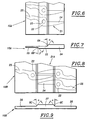
- FIG. 1 the blank 1 of a one-piece jaw intended to equip the protruding branch with a multi-grip pliers.
- This blank consists of a jaw 2 of constant large thickness E, typically of the order of 9 mm, and of a fixing heel 3 of constant thickness e much smaller, typically of the order of E / 2 , or about 4 mm.
- An intermediate bead 4 is provided between the jaw and the heel.
- the blank is symmetrical with respect to its median plane P.
- Heel 3 is delimited, on each face, by a straight shoulder 5, substantially perpendicular at plane P.
- shoulder 5 is bordered by a straight clearance groove 6.
- the shoulder 5 connects to a short flat surface 7 parallel to plane P, then joins the jaw root 2 by an inclined face 8.
- the angle ⁇ of this inclined face with the perpendicular to the plane P is preferably at least equal to 30 °, and for example close to this value.
- heel 3 is crossed by a wide oblong cutout 9 rounded ends.
- a succession of blanks 1 is produced from a profile of shape 10, obtained by extrusion, shown in Figures 2 and 3.
- This profile has the same section as the blank 1 when looking at the shoulders 5 at the end
- it consists of a part 2 with rectangular section, of constant thickness E, of a part 3 with rectangular section, of constant thickness e , and, between these two parts, part 4 in excess thickness.
- the latter presents, on the side of the game. 2, two faces 8 inclined at the above angle ⁇ ; on the other side, it has two faces 5 perpendicular to the median plane P, each bordered by a clearance groove 6.
- the faces 8 and 5 are connected on each side by a face 7 parallel to the plane P.
- FIG. 5 The assembly is shown in Figure 5 jaw 12, consisting of the blank 1 machined in the active region 13 ( Figure 1) of jaw 2, with two sheet metal parts 14, 15 of elongated shape, flat in their front region, which surround the heel 3, to achieve the protruding branch 16 of a pliers.
- Each piece 14, 15 ends, at the front, by a straight edge 17 which rests on the shoulder 5 corresponding all along it. This support, which is made reliable by the presence of the grooves of clearance 6, allows the clamping forces to be taken up when using the tool.
- Each piece 14, 15 further comprises two orifices 18 which each fit in an end round 19 of the cutout 9, as shown in phantom in Figure 1.
- the assembly parts 12, 14 and 15 is produced using two rivets 20 which pass through these orifices 18 as well as the cutout 19. During their compression, the rods of the two rivets swell, which presses them firmly against the rounded edges 19.
- Figures 6 and 7 show the realization by simply cutting out a series of one-piece members of clamp 21 in. a 10A shape profile.
- Each member 21 forms a half-mesh, or articulation half-zone, 22, provided with an orifice 23 for the passage of the hinge pin of the clamp; on the one hand from this area, a jaw 24 of the forceps; and on the other next to zone 22, a branch nucleus 25.
- the jaw 24 is of the beak type Universal pliers.
- the profile 10A has, in section, three successive parts of increasing thickness: one thick part 24 jaw side, an intermediate part 22 corresponding to the half-mesh, and a thin part 25 corresponding to the branch core.
- the profile On one side (the upper face in Figure 7), the profile is flat on all the parts 22 and 25, and an inclined face 8A along the aforementioned angle ⁇ connects this plane to the plane face parallel of part 24.
- the profile On the other side, the profile is flat on all parts 22 and 24, and one side 5B inclined at an angle ⁇ preferably at least equal to 30 °, for example equal to ⁇ , connects this plane to the face parallel plane of part 25.
- a succession of members 21 are obtained by simple cutting 10A profile, with their main direction substantially perpendicular to the length of the profile.
- the profile 10B has two thin side portions 26 of same thickness, and a thicker central part 27. It is flat on the whole of one of its faces, and on the other side, the part 27 is bordered by two faces 8C inclined at the angle ⁇ .
- the flat underside allows the use of a flat cutting die.
- Same 21A members can be cut in the profile 10C shown in Figures 10 and 11, which has a thin central part 26 and two thick side parts 27. Again, the profile has a completely flat face. In this case, the nozzles 24 are cut in parts 27, and these are the zones 22, 25 which are arranged upside down in the part central 26.
- Figures 12 and 13 illustrate a variant very close to the previous one. However, the area central 26 of profile 10D is wider, which allows to bring together the blanks 21A to each other cut.
- Variant 10F in Figures 16 and 17 does not differs from that in Figures 6 and 7 only in that the lower inclined face 8B is plumb with the upper inclined face 8A. 21B members obtained by cutting this profile 10F therefore differ correspondingly of the members 21.
- Figure 18 shows in perspective a gripper member blank 21A obtained by cutting the profile 10B, 10C, 10D or 10E.
- This draft includes a flat face and, on the other side, a change in thickness progressive 28 at the root of its beak 24.
- Figure 20 represents a 10G profile similar to that of Figures 14 and 15, and Figure 21 shows that from this profile, we can cut either a universal clamp member blank 21A such that that of Figure 18, a draft member 21C of round nose pliers.
- a universal clamp member blank 21A such that that of Figure 18, a draft member 21C of round nose pliers.
- Figure 21 shows that from this profile, we can cut either a universal clamp member blank 21A such that that of Figure 18, a draft member 21C of round nose pliers.
- Global tools making it possible to manufacture a range of pliers is therefore particularly economical.
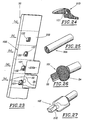
- Management of a fleet of shaped profiles can even be completely deleted if you start from a basic section with simple section in which we realize by forging, cold or hot, a succession of shaped profile sections in each of which there is a cutout, which is made in one step higher.
- This basic profile is forged in several steps ( Figure 23) to form a succession of sections 10H shaped profiles in each of which fits a cutout 33, which is for example that of the blank of the universal clamp 21D in Figure 24.
- Such a method eliminates the phase subsequent machining of the cutter 121.
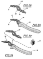
- Figures 28 to 36 illustrate three modes different finishing of a half clamp from a 21F clamp member blank which does not differ from the blank 21A of Figure 18 only by the presence of reliefs 36, such as notches and an orifice, on the core of branch 25.
- the reliefs 36 can be obtained by cut itself.
- This handle can be aluminum, aluminum alloy, or reinforced thermoplastic or thermosetting material or not.
- FIG. 30 we begins by threading by force, or at least with joint waterproof, on the core 25 a ring 40, then the mold for molding the handle on this ring.
- the Finished half clamp is shown in Figure 31.
- the ring 40 is made of a material having a some flexibility or ductility in order to adapt internally to dimensional variations of the nucleus. 25, and externally around the closed mold. This material is for example a plastic material or aluminum.
- the front part of the ring 40 externally enlarged, is visible at the front of the handle and extend it.
- the handle 38 made of plastic, is produced independently by molding and has a cavity 41 which opens at its front end through an opening 42 and laterally through an opening 43 (Figure 34).
- the walls of the cavity 41 have reliefs 44.
- the core 25 of the clamp member is introduced through the opening 42 ( Figure 35), then additional plastic 45 is molded in the cavity 41 to secure the two pieces ( Figure 36).
- the reliefs 36 of the clamp member, and possibly 44 of the handle improve the grip between the two parts after overmolding.
- finishing modes of branch described above with reference to Figures 28 to 36 are also applicable to metallic members obtained by any other suitable process, for example by forging or cutting / stamping flat sheets.
Description
La présente invention est relative à un procédé de fabrication d'ébauches métalliques de mors ou de noyaux de branches de pinces comprenant une mâchoire.The present invention relates to a process for manufacturing metal blanks bit or branch kernels pliers comprising a jaw.
Les techniques actuelles de fabrication des pièces métalliques de pinces, à savoir les mors des pinces multiprises et les têtes de travail et/ou les branches des autres types de pinces, imposent de gérer un parc d'outillage coûteux et complexe. Ces techniques connues sont en effet le forgeage ou le découpage/emboutissage de tôles plates (JP-A-6 076 235).Current manufacturing techniques for metal parts of pliers, namely the jaws of pliers and work heads and / or branches of other types of pliers, impose to manage an expensive and complex tool fleet. These techniques known are indeed forging or cutting / stamping of flat sheets (JP-A-6 076 235).
L'invention a pour but de permettre la réalisation industrielle de gammes étendues de pinces avec un outillage réduit, et donc de façon particulièrement économique.The invention aims to allow the industrial production of wide ranges of pliers with reduced tools, and therefore particularly economic.
A cet effet, le procédé de fabrication suivant l'invention, tel que défini dans la revendication 1, est caractérisé en ce qu'on decoupe le contour de chaque ébauche dans un tronçon de profilé de forme respectif d'épaisseur variable dont la section transversale correspond à au moins une section dans l'ensemble longitudinale de l'ébauche.To this end, the manufacturing process according to the invention, as defined in claim 1, is characterized in that one cuts the outline of each blank in a section of profile of respective shape of variable thickness whose cross-section transversal corresponds to at least one section overall longitudinal of the draft.
De préférence ce procédé peut comporter une ou plusieurs
des caractéristiques des revendications 2 à 10.Preferably, this process can include one or more
features of
L'invention a également pour objet un procédé
de fabrication d'une demi-pince,
selon les revendications 11 et 13, utilisant le procédé de l'invention.
Suivant une première
variante, on réalise comme décrit plus haut une ébauche
qui comporte un noyau de branche de pince, et on surmoule
une poignée de pince sur ce noyau. De façon avantageuse,
dans ce cas, le moule de surmoulage est fermé sur une
bague d'adaptation enfilée sur le noyau de branche.The invention also relates to a method
manufacturing a half-clamp,
according to
Suivant une deuxième variante, on réalise comme décrit plus haut plus haut une ébauche qui comporte un noyau de branche de pince, on introduit avec jeu le noyau de branche dans une cavité d'une poignée préformée, et on remplit l'espace restant libre dans cette cavité d'une matière de remplissage. Ladite cavité peut notamment déboucher vers l'avant et latéralement.According to a second variant, we realize as described above, above a draft which includes a pliers branch core, we introduce with play the branch core in a cavity of a preformed handle, and we fill the remaining free space in this cavity a filling material. Said cavity can in particular lead forwards and laterally.
Des exemples de mise en oeuvre de l'invention vont maintenant être décrits en regard des dessins annexés, sur lesquels :
- la Figure 1 représente en perspective une ébauche de mors de pince multiprise réalisée conformément à l'invention;
- la Figure 2 représente en perspective un profilé de forme à partir duquel l'ébauche de mors de la Figure 1 est réalisé;
- la Figure 3 représente la section de ce profilé;
- la Figure 4 illustre en perspective la découpe d'ébauches telles que celle de la Figure 1 dans ce profilé;
- la Figure 5 représente schématiquement, en coupe longitudinale, une branche de pince multiprise équipée d'un mors obtenu à partir de l'ébauche de la Figure 1;
- la Figure 6 illustre la découpe d'ébauches d'un membre de pince dans un profilé de forme conformément à l'invention;
- la Figure 7 représente la section du profilé de forme;
- les Figures 8, 10, 12, 14 et 16 sont des vues analogues à la Figure 6 mais relatives à d'autres profilés de forme;
- les Figures 9, 11, 13, 15 et 17 représentent les sections respectives de ces profilés de forme;
- la Figure 18 représente en perspective une ébauche de membre de pince obtenue à partir de l'un quelconque des profilés des Figures 8 à 15;
- la Figure 19 représente en perspective une ébauche de demi-pince réalisée conformément à l'invention;
- la Figure 20 représente en perspective un profilé analogue à celui des Figures 14 et 15;
- la Figure 21 illustre la découpe d'ébauches de deux membres de pince différents dans ce profilé;
- la Figure 22 représente en perspective un profilé de base à section rectangulaire;
- la Figure 23 illustre le forgeage de. tronçons localisés de profilé de forme dans ce profilé de base, ainsi que la découpe d'ébauches de demi-pince dans ces tronçons localisés;
- la Figure 24 représente en perspective l'ébauche ainsi obtenue;
- la Figure 25 représente en perspective un profilé de base à section circulaire;
- la Figure 26 illustre le forgeage de tronçons localisés de profilé de forme dans ce profilé de base;
- la Figure 27 illustre la découpe dans ces tronçons localisés d'ébauches de membre de pince;
- la Figure 28 représente en perspective une autre ébauche de membre de pince réalisée conformément à l'invention et usinée pour constituer un membre de pince;
- la Figure 29 représente en perspective le membre de pince correspondant, sur lequel une poignée de pince a été surmoulée;
- la Figure 30 représente en perspective le même membre de pince et une bague rapportée;
- la Figure 31 représente le même membre de pince équipé de la bague rapportée et sur lequel une poignée de pince a été surmoulée;
- les Figures 32 et 33 montrent schématiquement, en coupe longitudinale, deux variantes de la demi-pince de la Figure 29;
- la Figure 34 illustre en perspective un autre mode de réalisation d'une demi-pince à partir du membre de pince de la Figure 28;
- la Figure 35 est une vue en plan correspondante; et
- la Figure 36 est une vue en plan, partiel-. lement en coupe, montrant la demi-pince terminée.
- Figure 1 shows in perspective a blank of multi-grip pliers jaws produced in accordance with the invention;
- Figure 2 shows in perspective a shaped profile from which the jaw blank of Figure 1 is made;
- Figure 3 shows the section of this profile;
- Figure 4 illustrates in perspective the cutting of blanks such as that of Figure 1 in this profile;
- Figure 5 shows schematically, in longitudinal section, a branch of pliers equipped with a jaw obtained from the blank of Figure 1;
- Figure 6 illustrates the cutting of blanks of a clamp member in a shaped section according to the invention;
- Figure 7 shows the section of the shape profile;
- Figures 8, 10, 12, 14 and 16 are views similar to Figure 6 but relating to other shaped profiles;
- Figures 9, 11, 13, 15 and 17 show the respective sections of these shaped sections;
- Figure 18 shows in perspective a clamp member blank obtained from any of the profiles of Figures 8 to 15;
- Figure 19 shows in perspective a half-clip blank produced in accordance with the invention;
- Figure 20 shows in perspective a profile similar to that of Figures 14 and 15;
- Figure 21 illustrates the cutting of blanks of two different clamp members in this profile;
- Figure 22 shows in perspective a base profile with rectangular section;
- Figure 23 illustrates the forging of. localized sections of shape profile in this base profile, as well as the cutting of half-clamp blanks in these localized sections;
- Figure 24 shows in perspective the blank thus obtained;
- Figure 25 shows in perspective a basic profile with circular section;
- Figure 26 illustrates the forging of localized sections of shape section in this base section;
- Figure 27 illustrates the cutting in these localized sections of clamp member blanks;
- FIG. 28 shows in perspective another blank of gripper member produced in accordance with the invention and machined to constitute a gripper member;
- Figure 29 shows in perspective the corresponding clamp member, on which a clamp handle has been molded;
- Figure 30 shows in perspective the same clamp member and an attached ring;
- Figure 31 shows the same clamp member equipped with the attached ring and on which a clamp handle has been molded;
- Figures 32 and 33 schematically show, in longitudinal section, two variants of the half-clamp of Figure 29;
- Figure 34 illustrates in perspective another embodiment of a half clamp from the clamp member of Figure 28;
- Figure 35 is a corresponding plan view; and
- Figure 36 is a plan view, partially. in section, showing the half clamp finished.
On a représenté sur la Figure 1 l'ébauche 1
d'un mors monobloc destiné à équiper la branche entrepassante
d'une pince multiprise. Cette ébauche est constituée
d'une mâchoire 2 de forte épaisseur E constante,
typiquement de l'ordre de 9 mm, et d'un talon de fixation
3 d'épaisseur constante e beaucoup plus faible, typiquement
de l'ordre de E/2, soit de l'ordre de 4 mm. Un
bourrelet intermédiaire 4 est prévu entre la mâchoire et
le talon. L'ébauche est symétrique par rapport à son plan
médian P.There is shown in Figure 1 the blank 1 of a one-piece jaw intended to equip the protruding branch with a multi-grip pliers. This blank consists of a
Le talon 3 est délimité, sur chaque face, par
un épaulement 5 rectiligne, sensiblement perpendiculaire
au plan P. A sa racine, côté talon, l'épaulement 5 est
bordé par une rainure rectiligne de dégagement 6. De
l'autre côté, l'épaulement 5 se raccorde à une courte
surface plane 7 parallèle au plan P, puis rejoint la
racine de la mâchoire 2 par une face inclinée 8. L'angle
α de cette face inclinée avec la perpendiculaire au plan
P est de préférence au moins égal à 30°, et par exemple
voisin de cette valeur. Par ailleurs, le talon 3 est
traversé par une large découpe 9 de forme oblongue à
extrémités arrondies.
On réalise une succession d'ébauches 1 à
partir d'un profilé de forme 10, obtenu par extrusion,
représenté sur les Figures 2 et 3. Ce profilé a la même
section que l'ébauche 1 lorsqu'on regarde en bout les
épaulements 5. Ainsi, en reprenant les mêmes références
numériques que ci-dessus, il est constitué d'une partie
2 à section rectangulaire, d'épaisseur constante E, d'une
partie 3 à section rectangulaire , d'épaisseur constante
e, et, entre ces deux parties, d'une partie 4 en surépaisseur.
Cette dernière présente, du côté de la partie.
2, deux faces 8 inclinées suivant l'angle α précité; de
l'autre côté, elle présente deux faces 5 perpendiculaires
au plan médian P, bordées chacune d'une rainure de
dégagement 6. Les faces 8 et 5 sont reliées de chaque
côté par une face 7 parallèle au plan P.A succession of blanks 1 is produced from a profile of
Ainsi, comme représenté sur la Figure 4, il
est possible d'obtenir en une seule opération de découpe
du profilé 10, effectuée perpendiculairement au plan P,
une succession d'ébauches 1, suivant les contours
répétitifs 11 indiqués. On utilise bien entendu pour cela
une matrice et un poinçon tridimensionnels épousant
chacun la forme d'une face du profilé. Il est à noter que
la présence des rainures 6 permet d'obtenir un bon appui
plan sur les faces de la partie 3, jusqu'aux épaulements
5, tandis que l'inclinaison α des faces 8 facilite le
centrage du profilé et l'obtention d'une bonne qualité
de découpe.So, as shown in Figure 4, it
is possible to obtain in a single
On a représenté sur la Figure 5 l'assemblage
du mors 12, constitué de l'ébauche 1 usinée dans la
région active 13 (Figure 1) de la mâchoire 2, avec deux
pièces en tôle 14, 15 de forme allongée, planes dans leur
région avant, qui enserrent le talon 3, pour réaliser la
branche entrepassante 16 d'une pince multiprise.The assembly is shown in Figure 5
Chaque pièce 14, 15 se termine, à l'avant,
par un bord rectiligne 17 qui prend appui sur l'épaulement
5 correspondant tout le long de celui-ci. Cet appui,
qui est rendu fiable par la présence des rainures de
dégagement 6, permet de reprendre les efforts de serrage
lors de l'utilisation de l'outil. Chaque pièce 14, 15
comporte de plus deux orifices 18 qui s'inscrivent chacun
dans un arrondi d'extrémité 19 de la découpe 9, comme
indiqué en traits mixtes sur la Figure 1. L'assemblage
des pièces 12, 14 et 15 est réalisé au moyen de deux
rivets 20 qui traversent ces orifices 18 ainsi que la
découpe 19. Lors de leur compression, les tiges des deux
rivets gonflent, ce qui les plaque fermement contre les
bords des arrondis 19.Each
Les Figures 6 et 7 montrent la réalisation
par simple découpe d'une série de membres monoblocs de
pince 21 dans.un profilé de forme 10A.Figures 6 and 7 show the realization
by simply cutting out a series of one-piece members of
Chaque membre 21 forme une demi-maillure, ou
demi-zone d'articulation, 22, munie d'un orifice 23 pour
le passage de l'axe d'articulation de la pince; d'un côté
de cette zone, une mâchoire 24 de la pince; et de l'autre
côté de la zone 22, un noyau de branche 25. Dans
l'exemple représenté, la mâchoire 24 est du type bec de
pince universelle.Each
Le profilé de forme 10A présente, en section,
trois parties successives d'épaisseur croissante : une
partie épaisse 24 côté mâchoire, une partie intermédiaire
22 correspondant à la demi-maillure, et une partie mince
25 correspondant au noyau de branche. Sur une face (la
face supérieure sur la Figure 7), le profilé est plan sur
l'ensemble des parties 22 et 25, et une face 8A inclinée
suivant l'angle α précité relie ce plan à la face plane
parallèle de la partie 24. Sur l'autre face, le profilé
est plan sur l'ensemble des parties 22 et 24, et une face
5B inclinée suivant un angle β de préférence au moins
égal à 30°, par exemple égal à α, relie ce plan à la face
plane parallèle de la partie 25.The
Comme représenté sur la Figure 6, une
succession de membres 21 sont obtenus par simple découpe
du profilé 10A, avec leur direction principale sensiblement
perpendiculaire à la longueur du profilé.As shown in Figure 6, a
succession of
Dans la variante des Figures 8 et 9, le
profilé 10B comporte deux parties latérales minces 26 de
même épaisseur, et une partie centrale plus épaisse 27.
Il est plan sur la totalité d'une de ses faces, et sur
l'autre face, la partie 27 est bordée par deux faces 8C
inclinées suivant l'angle α. La face inférieure plane
permet d'utiliser une matrice de découpage plane.In the variant of Figures 8 and 9, the
Par simple découpe, on réalise à partir du
profilé 10B une succession de membres de pince 21A
analogues à celui des Figures 6 et 7 mais dans lesquelles
les parties 22 et 25 ont la même épaisseur. Les membres
21A sont découpés tête-bêche, avec les becs 24 imbriqués
les uns dans les autres dans la région centrale 27 du
profilé.By simple cutting, we realize from
Les mêmes membres 21A peuvent être découpés
dans le profilé de forme 10C représenté aux Figures 10
et 11, qui comporte une partie centrale mince 26 et deux
parties latérales épaisses 27. De nouveau, le profilé
présente une face entièrement plane. Dans ce cas, les
becs 24 sont découpés dans les parties 27, et ce sont les
zones 22, 25 qui sont disposées tête-bêche dans la partie
centrale 26. Same 21A members can be cut
in the
Les Figures 12 et 13 illustrent une variante
très voisine de la précédente. Toutefois, la zone
centrale 26 du profilé 10D est plus large, ce qui permet
de rapprocher les unes des autres les ébauches 21A à
découper.Figures 12 and 13 illustrate a variant
very close to the previous one. However, the area
central 26 of
La variante des Figures 14 et 15 est analogue
à celle des Figures 6 et 7, à ceci près que les zones
22 et 25 du profilé 10E ont la même épaisseur, ce qui
permet de donner au profilé 10E une face entièrement
plane. Les membres obtenus sont du type 21A.The variant of Figures 14 and 15 is similar
to that of Figures 6 and 7, except that the
La variante 10F des Figures 16 et 17 ne
diffère de celle des Figures 6 et 7 que par le fait que
la face inclinée inférieure 8B se trouve à l'aplomb de
la face inclinée supérieure 8A. Les membres 21B obtenus
par découpage de ce profilé 10F diffèrent par conséquent
de façon correspondante des membres 21.
La Figure 18 représente en perspective une
ébauche de membre de pince 21A obtenue par découpe du
profilé 10B, 10C, 10D ou 10E. Cette ébauche comporte une
face plane et, de l'autre côté, un changement d'épaisseur
progressif 28 à la racine de son bec 24.Figure 18 shows in perspective a
gripper member blank 21A obtained by cutting the
En augmentant la longueur de la ou de chaque
partie du profilé correspondant au noyau de branche 25
(partie 25 des Figures 6 et 7, partie(s) 26 des Figures
8 à 17), on peut réaliser de la même manière, par simple
découpe, une ébauche de demi-pince 29 telle que celle
représentée sur la Figure 19. Celle-ci ne diffère de
l'ébauche 21A de la Figure 18 que par le prolongement du
noyau 25 en une âme de demi-branche entière 30.By increasing the length of the or each
part of the profile corresponding to the branch core 25
(
Non seulement le procédé dé découpe décrit ci-dessus permet de réaliser industriellement à grande cadence, et de façon précise et économique, une ébauche donnée, mais encore il permet, à partir du même profilé, de réaliser toute une gamme d'ébauches, qui, par exemple, ne diffèrent les unes des autres que par la forme de la tête de travail.Not only the cutting process described above allows to realize industrially at large rate, and precisely and economically, a draft given, but still it allows, from the same profile, to produce a whole range of sketches, which, for example, differ from each other only in the form of the working head.
Ainsi, la Figure 20 représente un profilé 10G
analogue à celui des Figures 14 et 15, et la Figure 21
montre qu'à partir de ce profilé, on peut découper soit
une ébauche de membre de pince universelle 21A telle que
celle de la Figure 18, soit une ébauche 21C de membre de
pince coupante à bec rond. Bien entendu, on peut imaginer
bien d'autres configurations d'ébauches réalisées à
partir d'un même profilé de forme. L'outillage global
permettant de fabriquer une gamme de pinces est par suite
particulièrement économique.Thus, Figure 20 represents a 10G profile
similar to that of Figures 14 and 15, and Figure 21
shows that from this profile, we can cut either
a universal clamp member blank 21A such that
that of Figure 18, a
La gestion d'un parc de profilés de forme peut même être totalement supprimée si l'on part d'un profilé de base à section simple dans lequel on réalise par forgeage, à froid ou à chaud, une succession de tronçons de profilé de forme dans chacun desquels s'inscrit une découpe, que l'on réalise dans une étape ultérieure.Management of a fleet of shaped profiles can even be completely deleted if you start from a basic section with simple section in which we realize by forging, cold or hot, a succession of shaped profile sections in each of which there is a cutout, which is made in one step higher.
Ainsi, dans l'exemple des Figures 22 et 23,
on part d'un profilé de base ou feuillard 32 à section
rectangulaire, dont l'épaisseur est l'épaisseur
maximale à prévoir dans la découpe (à savoir l'épaisseur
E du bec 24 dans les exemples cités ci-dessus).Thus, in the example of Figures 22 and 23,
we start from a basic section or
Ce profilé de base est forgé en plusieurs
étapes (Figure 23) pour former une succession de tronçons
de profilés de forme 10H dans chacun desquels s'inscrit
une découpe 33, qui est par exemple celle de l'ébauche
de demi-pince universelle 21D de la Figure 24.This basic profile is forged in several
steps (Figure 23) to form a succession of
Ainsi, à partir du profilé rectangulaire illustré en (a), on effectue les étapes suivantes :
- (b) réalisation d'une découpe localisée 132, à peu près au centre d'un tronçon de profilé 232;
- (c) forgeage localisé de cette découpe pour
former le taillant 121 de l'ébauche; - (d) forgeage de la partie 232A du tronçon de profilé située d'un côté de la découpe forgée 132, pour l'amener à l'épaisseur désirée pour les parties 22 et 25 de l'ébauche; on obtient ainsi un tronçon de profilé de forme 10I; et
- (e) découpe de l'ébauche 21D à taillant 121 représentée à la Figure 24.
- (b) making a
localized cutout 132, approximately in the center of a section ofsection 232; - (c) localized forging of this cut to form the
cutting edge 121 of the blank; - (d) forging the
part 232A of the section of section located on one side of the forgedcutout 132, to bring it to the desired thickness for theparts - (e) cutting out the blank 21D with a
cutting edge 121 shown in FIG. 24.
Un tel procédé permet de supprimer la phase
ultérieure d'usinage du taillant 121.Such a method eliminates the phase
subsequent machining of the
De même, dans l'exemple des Figures 25 à 27,
on part d'un profilé de base 32A à section circulaire
(Figure 25), par exemple dévidé d'une bobine, et on
réalise par forgeage une succession de tronçons de
profilés de forme 10I (Figure 26) constitués chacun d'un
tronçon 33 à section rectangulaire suivi d'un tronçon 34
à faces planes, de faible épaisseur. La découpe dans
chaque tronçon 10I (Figure 27) donne naissance à un
membre de pince, dans cet exemple un membre 21E de pince
coupante. On remarque que dans cet exemple, la dimension
longitudinale de l'ébauche 21E est sensiblement parallèle
à la longueur du profilé.Likewise, in the example of Figures 25 to 27,
we start from a
Les Figures 28 à 36 illustrent trois modes
différents de finition d'une demi-pince à partir d'une
ébauche de membre de pince 21F qui ne diffère de l'ébauche
21A de la Figure 18 que par la présence de reliefs
36, tels que des encoches et un orifice, sur le noyau de
branche 25. Les reliefs 36 peuvent être obtenus par la
découpe elle-même.Figures 28 to 36 illustrate three modes
different finishing of a half clamp from a
21F clamp member blank which does not differ from the blank
21A of Figure 18 only by the presence of
L'ébauche ayant été usinée en 37 dans la zone
active du bec 24,.pour en constituer un membre de pince
39, dans l'exemple des Figures 28 et 29, la poignée 38
est simplement surmoulée sur le noyau 25. Cette poignée
peut être en aluminium, en alliage d'aluminium, ou en
matière thermoplastique ou thermodurcissable renforcée
ou non.The blank having been machined in 37 in the area
Dans la variante des Figures 30 et 31, on
commence par enfiler à force, ou du moins à joint
étanche, sur le noyau 25 une bague 40, puis on ferme le
moule de surmoulage de la poignée sur cette bague. La
demi-pince finie est représentée sur la Figure 31. La
bague 40 est constituée d'une matière présentant une
certaine souplesse ou ductilité afin de s'adapter
intérieurement aux variations dimensionnelles du noyau.
25, et extérieurement au contour du moule fermé. Cette
matière est par exemple une matière plastique ou de
l'aluminium. La partie avant de la bague 40, extérieurement
agrandie, est visible à l'avant de la poignée et
prolonge celle-ci.In the variant of Figures 30 and 31, we
begins by threading by force, or at least with joint
waterproof, on the core 25 a
Comme représenté aux Figures 32 et 33, en
variante, on peut effectuer sur la poignée 38 un second
surmoulage 138, formant un revêtement total (Figure 32)
ou partiel (Figure 33), en une matière relativement
souple ou "grip". On peut ainsi obtenir toute une gamme
de pinces à partir de la même poignée de base 38.As shown in Figures 32 and 33, in
variant, one can carry out on the handle 38 a
Dans la variante des Figures 34 à 36, la
poignée 38, en matière plastique, est réalisée indépendamment
par moulage et comporte une cavité 41 qui
débouche à son extrémité avant par une ouverture 42 et
latéralement par une ouverture 43 (Figure 34). Les parois
de la cavité 41 présentent des reliefs 44. Le noyau 25
du membre de pince est introduit à travers l'ouverture
42 (Figure 35), puis de la matière plastique complémentaire
45 est surmoulée dans la cavité 41 pour solidariser
les deux pièces (Figure 36). On peut bien entendu
modifier la poignée de la même manière qu'aux Figures 32
et 33.In the variant of Figures 34 to 36, the
Dans chacune des variantes des Figures 28 à
36, les reliefs 36 du membre de pince, et éventuellement
44 de la poignée, améliorent l'adhérence entre les deux
pièces après le surmoulage.In each of the variants of Figures 28 to
36, the
Il est à noter que les modes de finition de branche décrits ci-dessus en regard des Figures 28 à 36 sont également applicables à des membres métalliques obtenus par tout autre procédé approprié, par exemple par forgeage ou découpe/emboutissage de tôles planes.It should be noted that the finishing modes of branch described above with reference to Figures 28 to 36 are also applicable to metallic members obtained by any other suitable process, for example by forging or cutting / stamping flat sheets.
De plus, on peut, dans le cas d'une poignée. bi-injectée, appliquer la technique décrite au sujet d'un manche de tournevis dans le FR-A-2 730 658 au nom de la Demanderesse, à savoir, lors de la dernière opération de surmoulage, fermer le moule en appliquant une nervure de pincement de celui-ci sur un gradin de la partie injectée sous-jacente.In addition, it can, in the case of a handle. bi-injected, apply the technique described for a screwdriver handle in FR-A-2 730 658 in the name of Applicant, namely, during the last transaction of overmolding, close the mold by applying a rib of pinching of it on a step of the injected part Underlying.
Claims (14)
- Process for manufacturing metal blanks (1; 21; 21A; ...; 21F; 29) for the nose or cores of the arms of pliers comprising jaws, characterised in that the outline of each blank is cut out from a respectively shaped profiled length (10; 10A; ...; 10I) of variable thickness, the cross section of which corresponds to at least one section along the longitudinal extent of the blank.
- Process according to claim 1, characterised in that the shaped profiled length (10; 10A; ...; 10I) is in one piece and made of one material.
- Process according to claim 1 or 2, characterised in that the blank is cut out from a profile (10; 10A; ...; 10I) of constant cross section.
- Process according to claim 1 or 2, characterised in that the starting material is a basic profile (32; 32A) having a different cross section from the shaped profiled lengths (10H, 10I), localised lengths (10H; 10I) of shaped profile are produced from this basic profile by at least one forging process, and the blanks are cut out from each of these localised lengths.
- Process according to claim 4, characterised in that the basic profile (32; 32A) is a sheet or bar of rectangular or polygonal cross section, or a profile with a cross section in the shape of a closed curve, particularly a circle, notably unwound from a coil.
- Process according to any one of claims 1 to 5, characterised in that the shaped profiled lengths (10B; 10C; 10D; 10E; 10G; 10H; 10I) have on one side, over their full extent, a flat surface for abutting on a flat cutting die.
- Process according to any one of claims 1 to 5, characterised in that the shaped profiled lengths (10; 10A; ...; 10I) have at least one thickness changing surface (8; 8a; 8B; 8C) which is inclined, notably by at least 30°, relative to the perpendicular to the median plane (P) of said lengths.
- Process according to any one of claims 1 to 7, characterised in that the shaped profiled lengths (10) comprise at least one shoulder (5) substantially perpendicular to the median plane (P) thereof, the root of this shoulder being bordered in particular by a releasing groove (6).
- Process according to any one of claims 1 to 8, characterised in that the section of the shaped profiled lengths (10D; 10C; 10D) is symmetrical in the transverse direction, and in that blanks (21A) arranged head to tail are cut out therefrom.
- Process according to any one of claims 1 to 9, characterised in that the shaped profiled lengths (10G) are used to cut out at least two blanks of different shapes (21A, 21C).
- Process for producing half a pair of pliers, characterised in that a blank (21F) of the core of one arm (25) of the pliers is produced according to any one of claims 1 to 10, and a handle (38) is moulded onto this core.
- Process according to claim 11, characterised in that the overmoulding mould is closed over an adaptor ring (40) threaded onto the core of the arm (25).
- Process for producing half a pair of pliers, characterised in that a blank (21F) of the core of one arm of the pliers (25) is produced according to any one of claims 1 to 10, the core of the arm (25) is inserted with play in a cavity (41) in a preformed handle (38), and the space left free in this cavity is filled with a filling material (45).
- Process according to claim 13, characterised in that the cavity (41) of the preformed handle (38) opens forwards and sideways.
Applications Claiming Priority (3)
| Application Number | Priority Date | Filing Date | Title |
|---|---|---|---|
| FR9612141 | 1996-10-04 | ||
| FR9612141A FR2754196B1 (en) | 1996-10-04 | 1996-10-04 | METHOD FOR MANUFACTURING CLAMPS |
| PCT/FR1997/001737 WO1998015370A1 (en) | 1996-10-04 | 1997-10-01 | Method for making blanks for parts of pliers |
Publications (2)
| Publication Number | Publication Date |
|---|---|
| EP0935507A1 EP0935507A1 (en) | 1999-08-18 |
| EP0935507B1 true EP0935507B1 (en) | 2002-04-10 |
Family
ID=9496380
Family Applications (1)
| Application Number | Title | Priority Date | Filing Date |
|---|---|---|---|
| EP97943040A Expired - Lifetime EP0935507B1 (en) | 1996-10-04 | 1997-10-01 | Method for making blanks for parts of pliers |
Country Status (6)
| Country | Link |
|---|---|
| US (1) | US6318212B1 (en) |
| EP (1) | EP0935507B1 (en) |
| AU (1) | AU4465997A (en) |
| DE (1) | DE69711908T2 (en) |
| FR (1) | FR2754196B1 (en) |
| WO (1) | WO1998015370A1 (en) |
Families Citing this family (2)
| Publication number | Priority date | Publication date | Assignee | Title |
|---|---|---|---|---|
| KR20030090049A (en) * | 2002-05-21 | 2003-11-28 | 현대자동차주식회사 | Method for manufacturing aluminium lower arm of vehicle |
| TWI650064B (en) * | 2018-02-14 | 2019-02-11 | 慶璉實業股份有限公司 | Tree scissors seat manufacturing method |
Family Cites Families (13)
| Publication number | Priority date | Publication date | Assignee | Title |
|---|---|---|---|---|
| GB213812A (en) * | 1923-06-19 | 1924-04-10 | Gustav Klauke | Tool insulator specially for the handles of pliers and the like |
| FR1054724A (en) * | 1952-04-21 | 1954-02-12 | Manufacturing process of measuring vessels for liquids | |
| US2825248A (en) * | 1955-11-28 | 1958-03-04 | Fred E Ahlbin | Scissors and method of making |
| US3114973A (en) * | 1962-04-25 | 1963-12-24 | Ekco Products Company | Knife assembly |
| FI51063C (en) * | 1975-06-11 | 1976-10-11 | Fiskars Ab Oy | Mounting arrangement for scissors and similar plastic handles. |
| JPS6076235A (en) * | 1983-09-14 | 1985-04-30 | Riken Kaki Kogyo Kk | Manufacture of plyer |
| CA1306959C (en) * | 1987-11-02 | 1992-09-01 | James H. Sheets | Brake shoe rib and a method of making same |
| DE9112630U1 (en) * | 1991-10-10 | 1991-12-12 | Fa. Hans Plier, 5630 Remscheid, De | |
| US5244141A (en) * | 1992-05-15 | 1993-09-14 | Doolittle Milton A | Method of manufacturing multi-characteristic small thin flat metallic parts |
| US5253557A (en) * | 1992-11-12 | 1993-10-19 | The Triangle Tool Group, Inc. A Subsidiary Of The Triangle Corporation | Ergonomic handle construction for hand-held tools |
| US5528834A (en) * | 1994-01-12 | 1996-06-25 | Buck Knives, Inc. | Fixed-blade knife for rugged service and its manufacture |
| US5551323A (en) * | 1995-03-22 | 1996-09-03 | Beere Precision Medical Instruments, Inc. | Screwdriver handle |
| US5809853A (en) * | 1996-10-23 | 1998-09-22 | Hudson; Robert V. | Protective grip for pliers-type tool |
-
1996
- 1996-10-04 FR FR9612141A patent/FR2754196B1/en not_active Expired - Fee Related
-
1997
- 1997-10-01 WO PCT/FR1997/001737 patent/WO1998015370A1/en active IP Right Grant
- 1997-10-01 DE DE1997611908 patent/DE69711908T2/en not_active Expired - Lifetime
- 1997-10-01 EP EP97943040A patent/EP0935507B1/en not_active Expired - Lifetime
- 1997-10-01 AU AU44659/97A patent/AU4465997A/en not_active Abandoned
- 1997-10-01 US US09/269,884 patent/US6318212B1/en not_active Expired - Fee Related
Also Published As
| Publication number | Publication date |
|---|---|
| US6318212B1 (en) | 2001-11-20 |
| DE69711908T2 (en) | 2002-11-07 |
| FR2754196B1 (en) | 1998-12-18 |
| DE69711908D1 (en) | 2002-05-16 |
| WO1998015370A1 (en) | 1998-04-16 |
| FR2754196A1 (en) | 1998-04-10 |
| AU4465997A (en) | 1998-05-05 |
| EP0935507A1 (en) | 1999-08-18 |
Similar Documents
| Publication | Publication Date | Title |
|---|---|---|
| FR2482883A1 (en) | PRECISION FORGING METHOD WITH CLOSED DIES | |
| EP0935507B1 (en) | Method for making blanks for parts of pliers | |
| EP3286028B1 (en) | Extruded reinforcement beam with prepared deformation | |
| FR2483811A1 (en) | CHUCK CLAMPING JAW FOR A RIVET PUTTING TOOL, AND METHOD OF MAKING SAID JAW | |
| EP0792722A1 (en) | Cutting tool of the bolt cutter type | |
| EP0800474B1 (en) | Hollow, integral asymmetrical metal structure such as an aircraft wing slat trailing edge and method of manufacture | |
| EP0792704B1 (en) | Method of making wiper blades | |
| EP0635337A2 (en) | Process for the manufacture of a tool handle and tool supplied with a handle made by this process | |
| EP1930146A1 (en) | Spoke made from composite material for a spoke wheel | |
| EP0727289B1 (en) | Blank for a screwdriver, screwdriver and set of screwdrivers manufactured starting from such a blank, and corresponding manufacturing methods | |
| FR2754204A1 (en) | Tool branch manufacturing procedure, e.g. for one half of pliers | |
| FR2495986A1 (en) | Plastics handle for hammer - has hollow tip with protruding intermittent annular and lengthwise ribs | |
| FR2552830A1 (en) | BLIND RIVET WITH LARGE DIMENSIONAL SECONDARY HEAD | |
| FR2689968A1 (en) | Fencing blade. | |
| EP3611013A1 (en) | Method for producing spectacle arms | |
| FR3012055A1 (en) | PIECE FITTING WITH FASTENING LEG (S) | |
| FR2983120A1 (en) | Method for manufacturing wheel of car, involves depositing paint layer of color in basin by serigraphy, and machining diamond part of wheel located around basin by removing surface layer of wheel to provide aspect specific to machined part | |
| EP3431231A1 (en) | Method of manufacturing a forged knife and forged knife | |
| EP0868266B1 (en) | Method for making a tool handle, and related tool | |
| EP1547734B1 (en) | Method for manufacturing a knife with cast aluminium bolster, and device for implementing such a method | |
| FR2642268A1 (en) | Process for the manufacture of microperforated cheese moulds, and mould obtained by this process | |
| WO2022263588A1 (en) | Methods for producing a stiffened structural aircraft panel by fsw welding | |
| US341415A (en) | James d | |
| FR2586606A1 (en) | Method for manufacturing a knife blade assembly blank, and knife obtained from such a blank | |
| FR2702400A1 (en) | Improvement for tooling intended to be used for the impact extrusion of components made of light alloy |
Legal Events
| Date | Code | Title | Description |
|---|---|---|---|
| PUAI | Public reference made under article 153(3) epc to a published international application that has entered the european phase |
Free format text: ORIGINAL CODE: 0009012 |
|
| 17P | Request for examination filed |
Effective date: 19990406 |
|
| AK | Designated contracting states |
Kind code of ref document: A1 Designated state(s): DE GB IT NL SE |
|
| 17Q | First examination report despatched |
Effective date: 19990831 |
|
| GRAG | Despatch of communication of intention to grant |
Free format text: ORIGINAL CODE: EPIDOS AGRA |
|
| GRAG | Despatch of communication of intention to grant |
Free format text: ORIGINAL CODE: EPIDOS AGRA |
|
| GRAH | Despatch of communication of intention to grant a patent |
Free format text: ORIGINAL CODE: EPIDOS IGRA |
|
| REG | Reference to a national code |
Ref country code: GB Ref legal event code: IF02 |
|
| GRAH | Despatch of communication of intention to grant a patent |
Free format text: ORIGINAL CODE: EPIDOS IGRA |
|
| GRAA | (expected) grant |
Free format text: ORIGINAL CODE: 0009210 |
|
| AK | Designated contracting states |
Kind code of ref document: B1 Designated state(s): DE GB IT NL SE |
|
| PG25 | Lapsed in a contracting state [announced via postgrant information from national office to epo] |
Ref country code: NL Free format text: LAPSE BECAUSE OF FAILURE TO SUBMIT A TRANSLATION OF THE DESCRIPTION OR TO PAY THE FEE WITHIN THE PRESCRIBED TIME-LIMIT Effective date: 20020410 |
|
| REF | Corresponds to: |
Ref document number: 69711908 Country of ref document: DE Date of ref document: 20020516 |
|
| PG25 | Lapsed in a contracting state [announced via postgrant information from national office to epo] |
Ref country code: SE Free format text: LAPSE BECAUSE OF FAILURE TO SUBMIT A TRANSLATION OF THE DESCRIPTION OR TO PAY THE FEE WITHIN THE PRESCRIBED TIME-LIMIT Effective date: 20020710 |
|
| GBT | Gb: translation of ep patent filed (gb section 77(6)(a)/1977) |
Effective date: 20020712 |
|
| NLV1 | Nl: lapsed or annulled due to failure to fulfill the requirements of art. 29p and 29m of the patents act | ||
| PLBE | No opposition filed within time limit |
Free format text: ORIGINAL CODE: 0009261 |
|
| STAA | Information on the status of an ep patent application or granted ep patent |
Free format text: STATUS: NO OPPOSITION FILED WITHIN TIME LIMIT |
|
| 26N | No opposition filed |
Effective date: 20030113 |
|
| PGFP | Annual fee paid to national office [announced via postgrant information from national office to epo] |
Ref country code: GB Payment date: 20100923 Year of fee payment: 14 |
|
| PGFP | Annual fee paid to national office [announced via postgrant information from national office to epo] |
Ref country code: DE Payment date: 20101012 Year of fee payment: 14 |
|
| PGFP | Annual fee paid to national office [announced via postgrant information from national office to epo] |
Ref country code: IT Payment date: 20101027 Year of fee payment: 14 |
|
| REG | Reference to a national code |
Ref country code: GB Ref legal event code: 732E Free format text: REGISTERED BETWEEN 20130404 AND 20130410 |
|
| GBPC | Gb: european patent ceased through non-payment of renewal fee |
Effective date: 20121001 |
|
| PG25 | Lapsed in a contracting state [announced via postgrant information from national office to epo] |
Ref country code: GB Free format text: LAPSE BECAUSE OF NON-PAYMENT OF DUE FEES Effective date: 20121001 Ref country code: DE Free format text: LAPSE BECAUSE OF NON-PAYMENT OF DUE FEES Effective date: 20130501 |
|
| REG | Reference to a national code |
Ref country code: DE Ref legal event code: R119 Ref document number: 69711908 Country of ref document: DE Effective date: 20130501 |
|
| PG25 | Lapsed in a contracting state [announced via postgrant information from national office to epo] |
Ref country code: IT Free format text: LAPSE BECAUSE OF NON-PAYMENT OF DUE FEES Effective date: 20121001 |